-
How to solder surface mount chip?
07/16/2016 at 10:50 • 0 commentsEventually I submit one product for Tindie.com (at this moment, I am not sure it will be admitted or not..) and it is a kit requires full assembly and I guess relatively good soldering skill and experience is required. (I think most of hackaday.com people have excellent soldering skill, though)
So here I would show how to solder SMT in quick and clean manner.
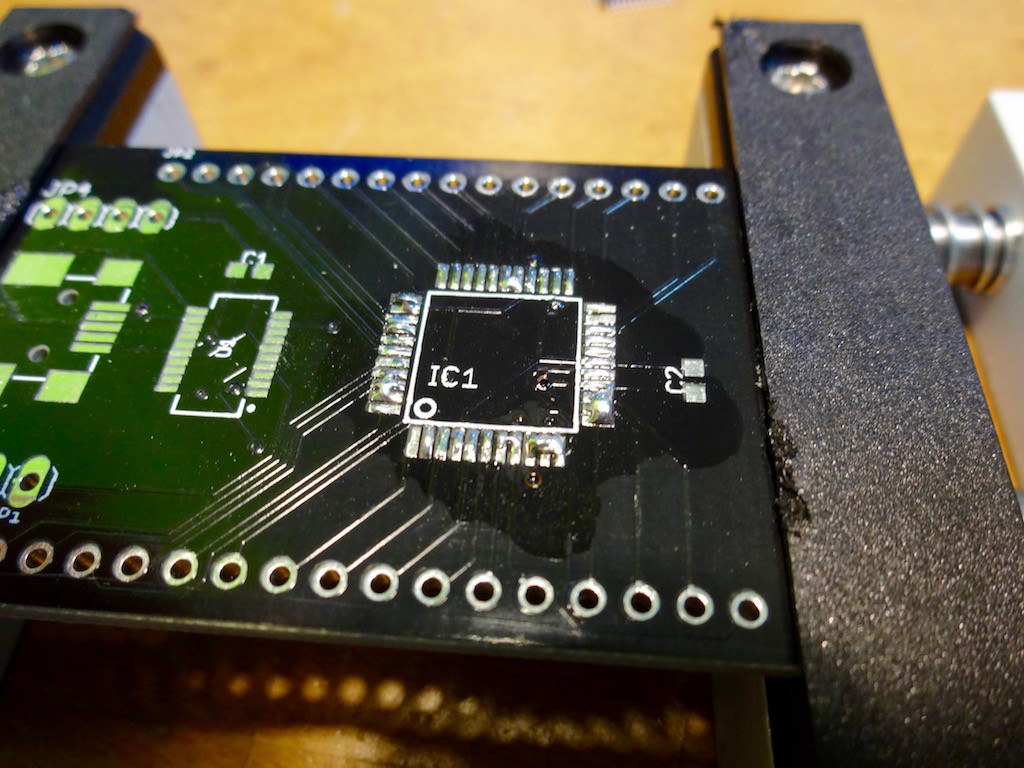
Step1: Put enough solder on electrode.
![]()
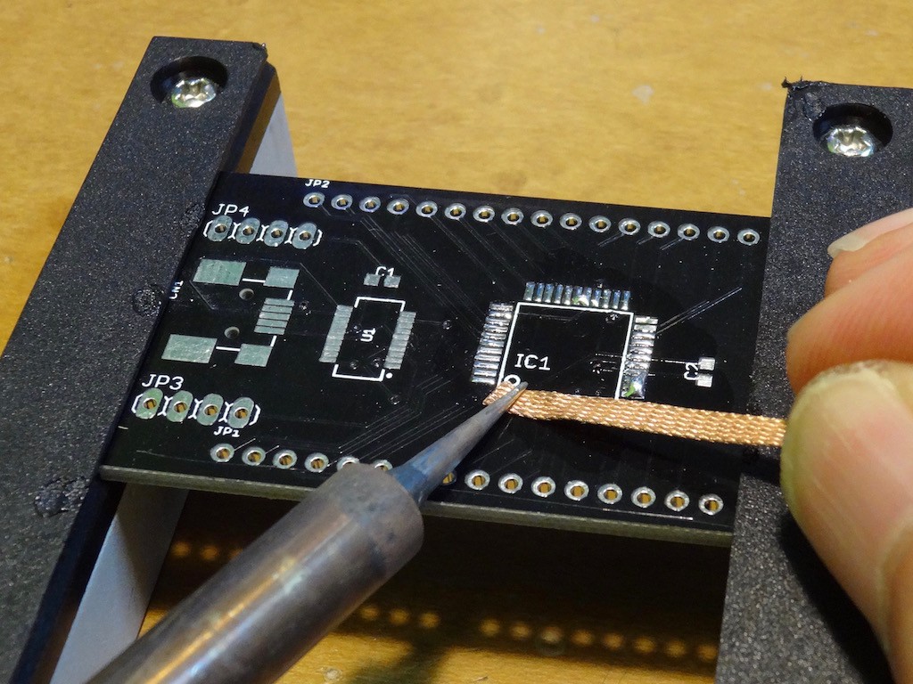
Step 2: Remove solder by de-solder braid
Not all of solder but most solder should be removed. Residue will work as glue!
![]()
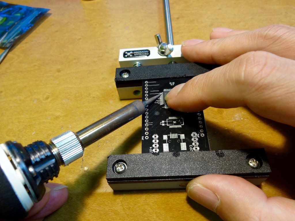
Step 3: Carefully align chip and gently push every electrode
![]()
Alignment is quite important but your hand will be enough good tool. Just gently push by soldering iron is enough to connect. No additional solder is needed. If you have some concern, add small amount of solder for each electrode.
![]()
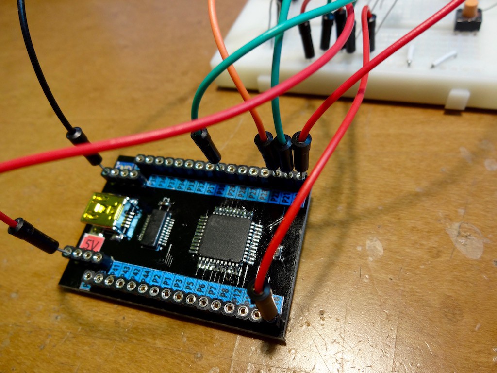
Complete! Have fun!
-
4bit CPU in CPLD
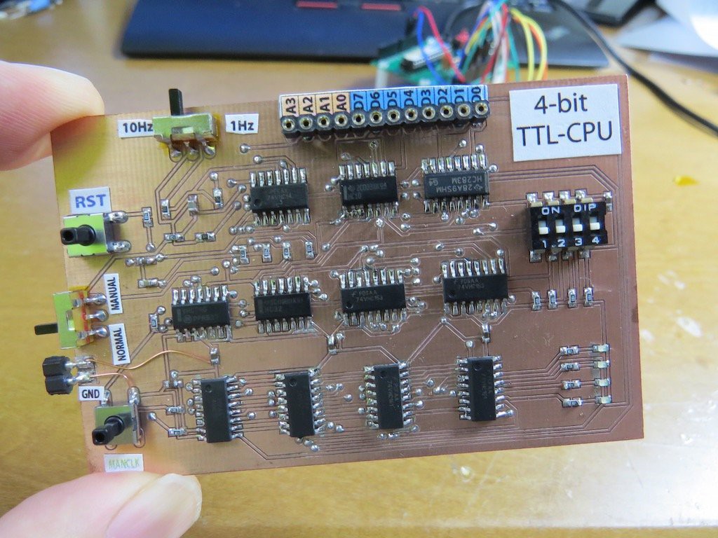
12/21/2015 at 08:58 • 1 commentBefore I made a PCB of 4bit TTL based CPU in another project,
![]()
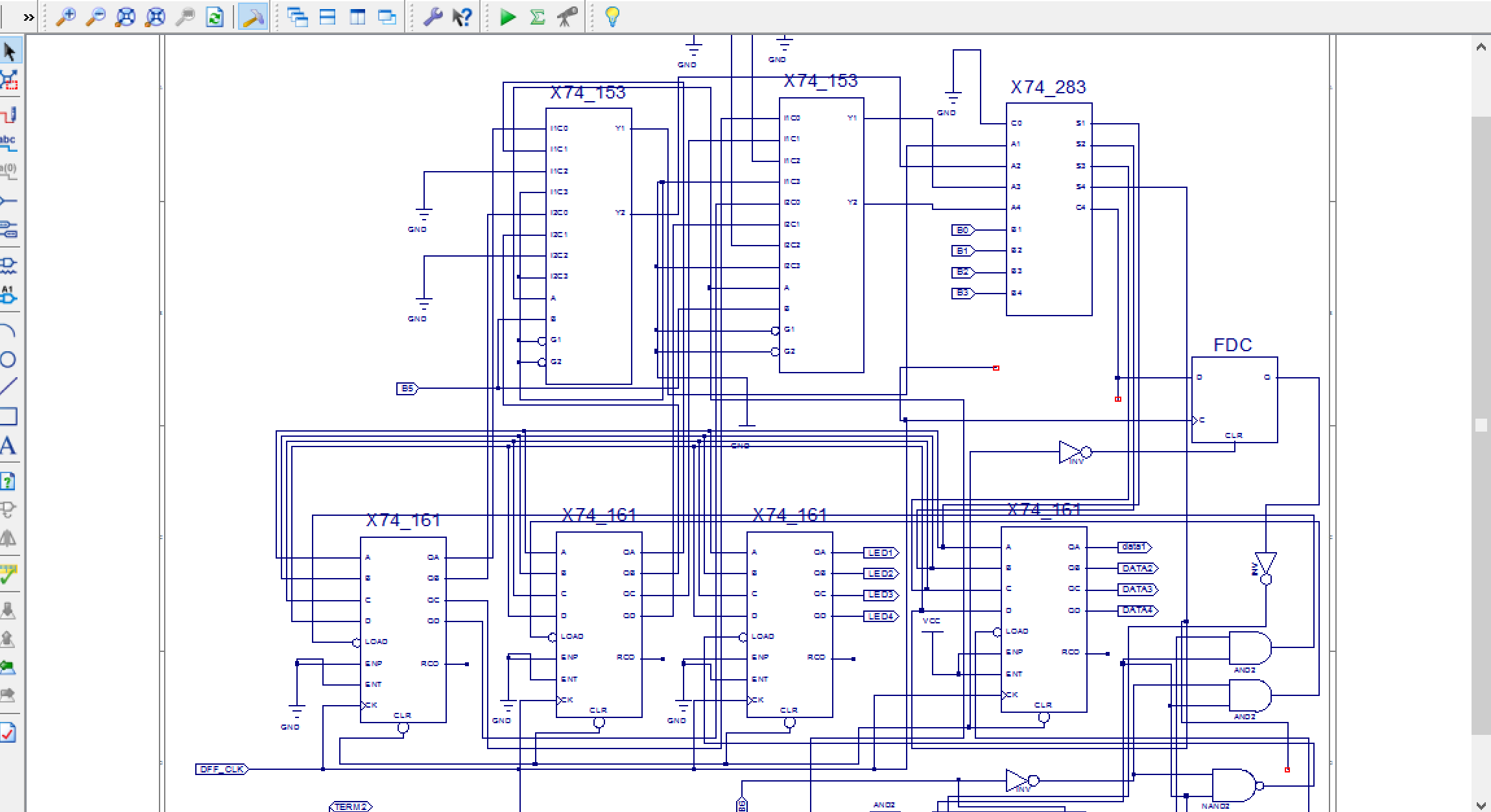
and this time I implemented it in CPLD. Actually this is a bit surprise for me to know that
![]()
This CPU is made by "pure schematic drawing without HDL writing" !! ISE has lots of pre-defined 74 series components and just select it and connect wire will provide the circuit what you want!
I know, this schematic writing is NOT main stream of CPLD/FPGA implementation but if some student who is learning basic logic circuit, and hit on great idea, just writing schematic is very handy way to realise circuit!! I guess schematic implementation still has lots of potential for education purpose. I am not sure someone will try to make same 4-bit CPU, but already related sources are uploaded to github. And also XC95144XL board (with 3.3V regulator, FT231XS) schematic are also uploaded to github.
As same as "real TTL implementation", CPU operation is confirmed with ROM, which is emulated by Arduino. You may think LED blinking is just blinking, but
prog[0b0000]=0b10110001; //OUT(1011) "0001" to LED
prog[0b0001]=0b10110010; //OUT(1011) "0010" to LED
prog[0b0010]=0b10110100; // same till 0b1110
prog[0b0011]=0b10111000;
prog[0b0100]=0b10111001;
prog[0b0101]=0b10111010;
prog[0b0110]=0b10111100;
prog[0b0111]=0b10111101;
prog[0b1000]=0b10111110;
prog[0b1001]=0b10111111;
prog[0b1010]=0b10110000;
prog[0b1011]=0b10111111;
prog[0b1100]=0b10110000;
prog[0b1101]=0b10111111;
prog[0b1110]=0b10110000;
prog[0b1111]=0b11110000; // JMP(1111) to "0000" first of program
this code is running on CPU in CPLD! Have fun! -
YES more modern CPLD board!
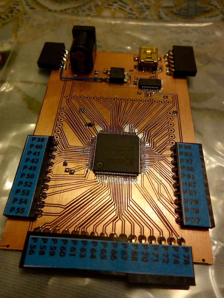
12/18/2015 at 12:55 • 0 commentsI completely know and understood XC9536 (without XL) is obsolete long time ago (in dog year). I explained why I used XC9536 is just I ordered too much ones for 68008 completion. Some wise people pointed out why I use old CPLD (may be my explanation was not understandable English) and this time,
![]()
I ordered at digikey for just one XC95144XL (not ten package for this time) and made much more modern CPLD learning board! YES, IT IS 3.3 V!!
Not only availability problem and voltage problem, XC95144 naturally can handle 4-times couplex circuit than 9536. Indeed I already implement 4-bit CPU which I introduced in another project and binary downloading works perfectly, as same as previous XC9536 board procedure. !!
-
Dummy's questions regarding CPLD
12/14/2015 at 09:32 • 7 commentsCPLD is a programmable logic and NOT analogue component but when I think about logic component in 74 series, they are working for some exceptional operation. Here I confirmed two "exceptional" cases. These fact should be well known by experts but please enjoy it.(Question 1) CPLD can organise RC oscillator?
Widely square wave generation is realised by 7404 or 7414 but is it possible by CPLD?
The answer is in the following movie..
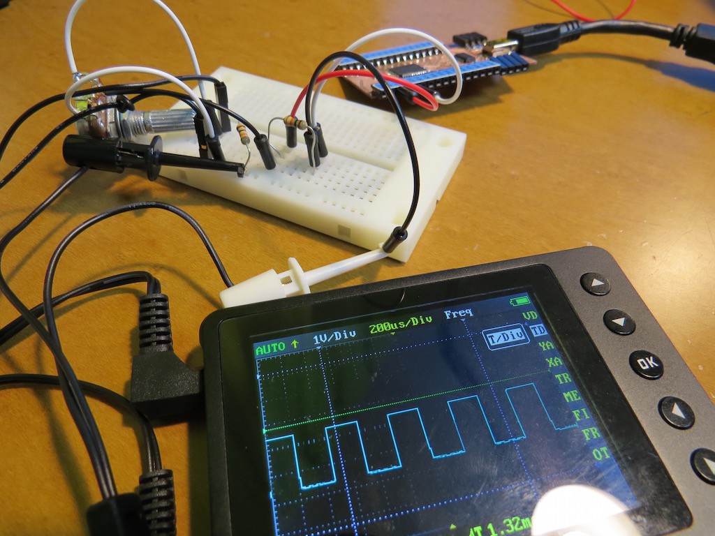
(Question 2) CPLD can work as analogue amplifier??
It is well known that inverter in 7404 can work as analogue amplifier by putting proper feedback resistors. My question is, the inverter in CPLD can work as amplifier by proper resistor?
![]()
The answer was, NO! The inverting signal is generated by some "artificial" (I know it is not good word, but synthesized?) way, not by N and P channel complementary circuit and voltage feedback by resistor network does not work.
Have fun!
Very simple CPLD trainer
Very simple CPLD prototyping board, where .svf can be uploaded through USB! Total cost ($4) is comparable with Rasp Zero
 kodera2t