 Muphins
The OLED Screen
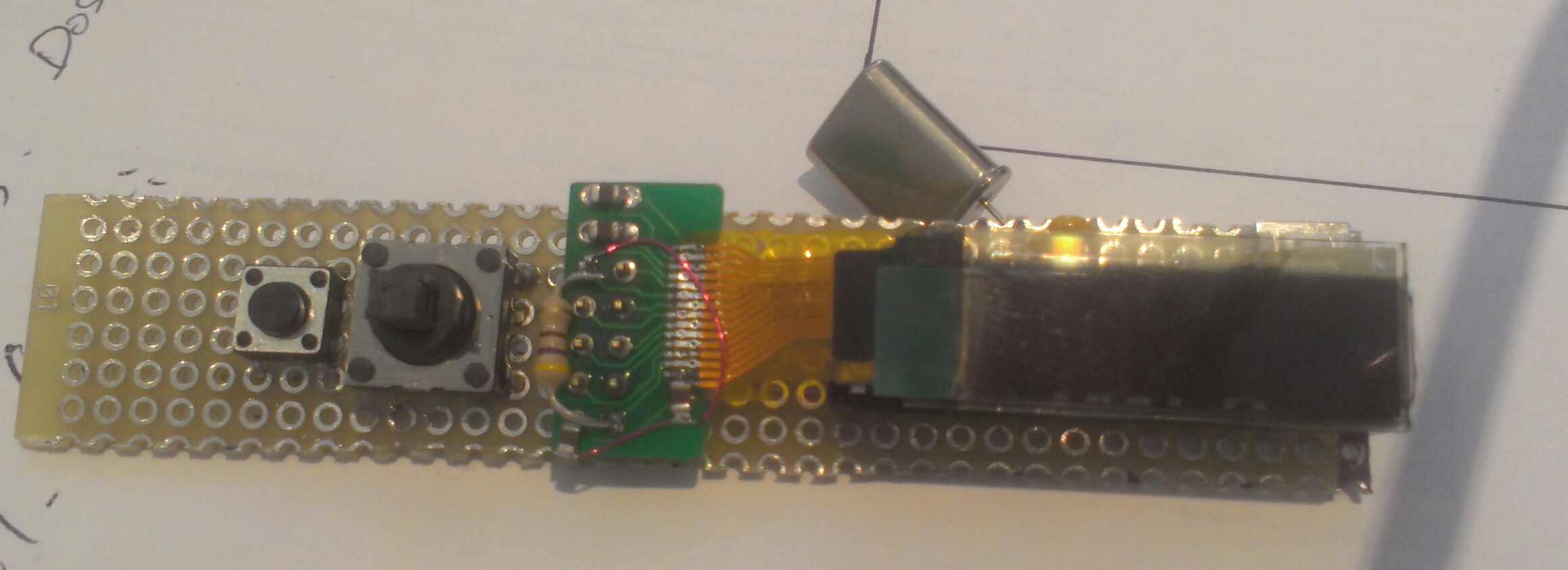
It was bought at Adafruit. I made all the testing and code with it on a breadboard, when it was done I unsoldered the screen and necessary components and soldered everything back on an half SOIC-28 adapter (same sapcing as the ribbon, minus one pin) so i could fit it (the adafruit board is way too large).
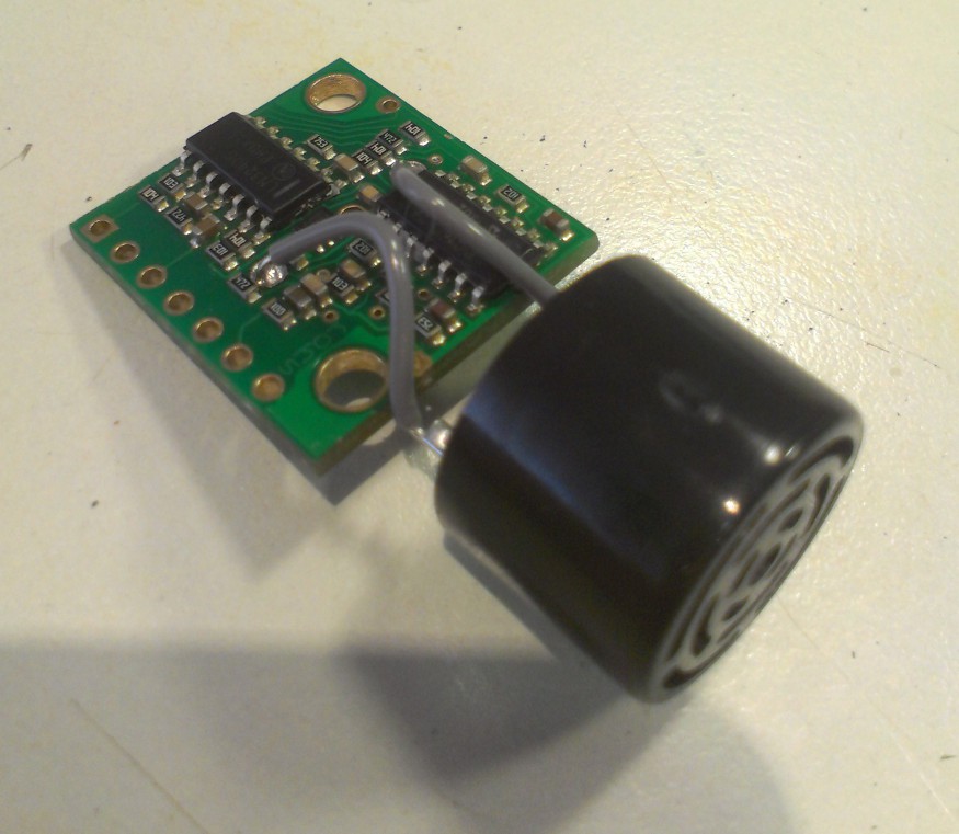
Ultrasonic RangeFinder
Also bought at Adafruit. As for the OLED screen I had to modify it to make it fit in a tube (the square board would have its corner stick out of the case).
Sound
Actualy the most interresting part of this project.
The Amp+Speaker part is made in the worst possible way: Its a BC547 transistor directly driving a smartphone speaker.
The sound generation however is a bit more achieved. I took the 8-bit raw data of the sonic's soundwave (explained later) and put it in a PROGMEM array. A 16-bit timer generates an interrupt in wich the program reads the values in the array, one by one at a frequency of 44 kHz (this frequency changes depending on the distance measured by the range-finder). The read value is then loaded on an 8-bit timer that generates a PWM signal at 62 kHz. Apparently the speaker's impedence is sufficient to filter correctly the PWM signal and lets a clear sound output.
How to get the 8-bit raw soundwave data:
First, i downloaded the original Sonic Screwdriver sound. Editing the file with Audacity I isolated a part that is the shortest posible, repeats nicely and still sounds like the Sonic Screwdriver. Then I exported the sound as a RAW unsigned 8-bit PCM file (in the save dialog select the type "Other uncompressed formats" then click Options").
The next step is to read the file with an hexadecimal editor (I used Frhed) and save the data in hexadecimal form. With Frhed I obtained something like this:
807f7e7d7b7a7a7b7d<br>1868c90918f8a837b7<br>6c666469748496a4ad<br>ca2907a65534b4f5f7<br>94acbbbeb29c80624a
and to make an array we need something more like that:
0x80, 0x7f, 0x7e, 0x7d, 0x7b, 0x7a, 0x7a, 0x7b, 0x7d8
So I wrote a little program in VB.net to reformat my 11k bytes of raw data. link , souce
Here is the C sources for the microcontroller.
When using arduino IDE, you have to comment the interrupt routine for timer0 overflow "ISR(TIMER0_OVF_vect)" in the "hardware/arduino/avr/cores/arduino/wiring.c" file (around line 44).
DISCLAMER: The code I made is a total mess of obscures variable names, commented stuff used for debug or testing and very little explaination, and contains some errors (that have no impact at the use, but if you copy paste some parts, do it with care).
I am actualy working on an other project, but one day I will rewrite this. However, if you have any question, ask me and I will answer as clearly as I can.


 lucio
lucio
 Anders Nielsen
 John Anderson
 Simon Merrett
Oh its amazing to see this type of unique project information I am also working on a range finder project you can see here.