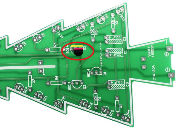
DIY solder kit. The flashing Christmas tree kit consists of three circuit boards, 37 LEDs that alternate flashing, and dual power sources.
To make the experience fit your profile, pick a username and tell us what interests you.
We found and based on your interests.
Schematic and Theory of Operation
Each of the 10K resistors and 47uF capacitors form an RC oscillator that periodically pushes the associated transistor on. The three sets of RC oscillators are transistors are connected in a loop to keep them cycling out of phase which makes the blinking appear random around the tree. When the transistor is "on" current passes through a bank of 6 LEDs and their 1K current limiting resistor causing that bank to blink on. If you're looking for an adveture, trying adjusting the value of one (or more) of the 10K resistors a bit to change the blink rate of the LEDs.
Populating the Resistors
Begin soldering by stuffing the resistors. Resistors are not polarized in anyway, which means that you can insert them in either direction.
Use a resistor color code chart or app to identify the different resistor values and make sure to insert them into the correct holes.
In some of 3D Christmas Tree kits, a couple of the 1K resistors are replaced with 330 ohm resistors. When available, the 330 ohm resistors should be used for R2 instead of the specified 1K resistor. According to the numbering system that we have used, R2 is the current limiting resistor for the green LED bank (D1-D6). Using this lower resistance allows the green LEDs to glow a tiny bit brighter, which can mitigate the fact that green LEDs often appear a little dimmer than the red and yellow LEDs.
In the end, the value of the current limiting resistors (R2, R4, R6, and R7) is somewhat forgiving and can anywhere around 300 ohms to 3K.
The value for R7 is
specified on the higher end (at 2K) because R7 is the current limiting
resistor for the red LED D19 at the top of the tree. Since D19 does not
blink, it may appear much brighter, so the higher 2K resistance
balances the brightness a bit with respect to the other LEDs.
Are you new to soldering? There are a lot of great guides and videos online about soldering. Here is an example:
http://www.instructables.com/id/How-to-Solder-a-Through-hole-Component/
If you feel that you need additional assistance with soldering, try to find a local maker group or hacker space in your area. Also, amateur radio clubs are always excellent sources of electronics experience.
Transistors
When soldering in the transistors, be sure to align the flat side of the
transistor to the flat side of the white outline on the printed circuit
board (PCB). This ensures that the transistor is wired in the correct
direction.
Create an account to leave a comment. Already have an account? Log In.
I am having issues with my trees (yes, I build several tree's). I have the so called colorful kit with the white LED which light in three colors.
Problem is, that some LEDs do not light after a while and I don't know why. Regardless if Battery powered or USB-powered, some LEDs does light after a while.
Can someone please support me how to find the issue and how to solved and of course explain what was happening? I think it could be a problem with one of the transistors but I still could not figured out how this tree works.
Thankful for all support,
Richard.
We've tried to build this circuit on the breadboard but only get solid lit LED's. We used 22 microF caps as the schematic showed that value. Then we tried 100 microF but that made no difference. Using 9V made no difference either. LED's are blue 1.8mm with fowrad current of 25mA. NPN transistors is what we have so that ties in with the schematic. What can we be doing wrong?
We desinged and 3D printed a cover for this LED Christmas tree. Download it at http://www.thingiverse.com/thing:1955231 . See also the making of video:
This seems to be an improvement over the Velleman kit http://www.amazon.com/Velleman-MK130-3D-Xmas-Tree/dp/B0006HJSIW/
I like it!
Become a member to follow this project and never miss any updates
Nice overview. I built this kit last year
but would like to slow down the rate of change. Any suggestions for some trimmer pots instead of the static resistors to allow for such tweaking?