 jlonglaw
-
1Step 1
Schematic and Theory of Operation
![]()
![]()
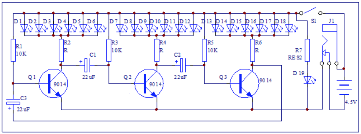
Each of the 10K resistors and 47uF capacitors form an RC oscillator that periodically pushes the associated transistor on. The three sets of RC oscillators are transistors are connected in a loop to keep them cycling out of phase which makes the blinking appear random around the tree. When the transistor is "on" current passes through a bank of 6 LEDs and their 1K current limiting resistor causing that bank to blink on. If you're looking for an adveture, trying adjusting the value of one (or more) of the 10K resistors a bit to change the blink rate of the LEDs.
-
2Step 2
Populating the Resistors
![]()
Begin soldering by stuffing the resistors. Resistors are not polarized in anyway, which means that you can insert them in either direction.
Use a resistor color code chart or app to identify the different resistor values and make sure to insert them into the correct holes.
In some of 3D Christmas Tree kits, a couple of the 1K resistors are replaced with 330 ohm resistors. When available, the 330 ohm resistors should be used for R2 instead of the specified 1K resistor. According to the numbering system that we have used, R2 is the current limiting resistor for the green LED bank (D1-D6). Using this lower resistance allows the green LEDs to glow a tiny bit brighter, which can mitigate the fact that green LEDs often appear a little dimmer than the red and yellow LEDs.
In the end, the value of the current limiting resistors (R2, R4, R6, and R7) is somewhat forgiving and can anywhere around 300 ohms to 3K.
The value for R7 is specified on the higher end (at 2K) because R7 is the current limiting resistor for the red LED D19 at the top of the tree. Since D19 does not blink, it may appear much brighter, so the higher 2K resistance balances the brightness a bit with respect to the other LEDs.
Are you new to soldering? There are a lot of great guides and videos online about soldering. Here is an example:http://www.instructables.com/id/How-to-Solder-a-Through-hole-Component/
If you feel that you need additional assistance with soldering, try to find a local maker group or hacker space in your area. Also, amateur radio clubs are always excellent sources of electronics experience.
-
3Step 3
Transistors
![]()
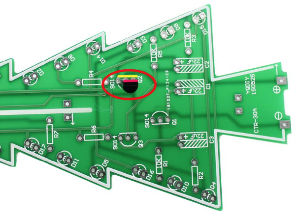
When soldering in the transistors, be sure to align the flat side of the transistor to the flat side of the white outline on the printed circuit board (PCB). This ensures that the transistor is wired in the correct direction.
-
4Step 4
Capacitors
![Picture of 3D Tree: Capacitors]()
Solder in the electrolytic capacitors. These are definitely polarized. There is usually a "-" marking along one side of the can and also the longer lead is positive while the shorter lead is negative. Be certain that the positive and negative terminals are matched to the indications on the PCB silk screen printing. As a double check, the solder pad for the positive pin is often square, while the negative pad is round. The square pad is sometimes called the "pin one indicator" and this applies to multi-lead packages like DIP integrated circuits as well. Leave enough slack in the leads to be able to bend the capacitor over onto its side once it is soldered into place.
-
5Step 5
LEDs
![Picture of 3D Tree: LEDs]()
Diodes (including LEDs) are also polarized. Be certain to observe that the long lead is positive and the short is negative. Again observe the silk screen printing on the PCB or that the positive solder pad is square. When soldering the LEDs, be sure the keep the same colors grouped together with a common resistor and transistor as show in our schematic and parts list. If you attempt to drive mixed color LEDs with the same current limiting resistor and switching transistor, you will likely find that one color glows brighter and the other color doesn't light up at all or only very dimly.
When soldering the LEDs into place, leave slack in the leads so that the LED can be bent off to the side once it is attached. Note that we have not yet soldered in the D19 LED at the very tip of the tree.
-
6Step 6
Test each PCB
![Picture of 3D Tree: Test each PCB]()
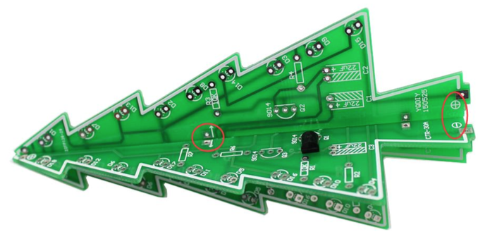
Once each of the Tree PCBs are fully populated (except for the D19 LED at the tip), they can be tested by placing about 5VDC onto the "+" and "-" pads at the very bottom of the tree. For example, you can place some AA batteries into the battery housing and touch the wires to the correct pads on the PCB. The LEDs should blink and cycle with colorful holiday goodness. If they do not, check the polarities (directions) of the power wires, the LEDs, the caps, and the transistors. If you were careful with all of the polarities while soldering, there should be no problems.
-
7Step 7
Base PCB
![Picture of 3D Tree: Base PCB]()
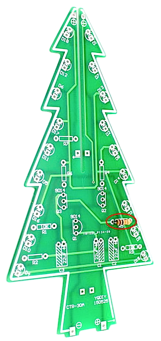
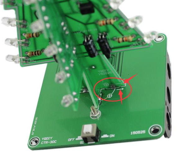
Solder the power button and the power terminal onto the Base PCB. When inserting the power button, the notched side of the button should face the nearest edge of the PCB as shown. A piece of resistor lead that was trimmed off earlier may be wrapped around the power terminal and soldered to the PCB as a stain relief to make the connector more robust while inserting the power plug.
The battery pack can be bolted into the base PCB as shown. The wires from the battery pack can be fed up into the PCB trimmed and soldered to the power pads.
-
8Step 8
Final Assembly
![]()
Slide the two tree halves into one another being careful to bend any of the components (such as the transistors) our of the way if they catch onto one another. Once the sides are aligned, solder the pads together where the halves touch.
![]()
Now the top LED (D19) can be attached and trimmed.
![]() Lastly, insert the tree into the base PCB being careful to
observe the "+" and "-" designations on all three PCBs. Solder the tree
to the base PCB.
Lastly, insert the tree into the base PCB being careful to
observe the "+" and "-" designations on all three PCBs. Solder the tree
to the base PCB.Your 3D LED Tree can be powered from the battery pack OR the power terminal USB adapter. When the power terminal is inserted, the batteries are out of the circuit, so it is fine to leave the batteries installed while using the USB power adapter.
WARNING: Some hobbyists have found that these low-power USB adapters do not work well with adapters to non-US power mains. If you are using the 3D Tree kit outside the US, please exercise caution. You can power the USB plug from a computer, power pack, or phone charger as well to avoid using the low-power adapter. Wherever you use the 3D Tree, and no matter which power supply you use, please be cautious and do not leave the 3D Tree operating unattended.
3D LED Christmas Tree
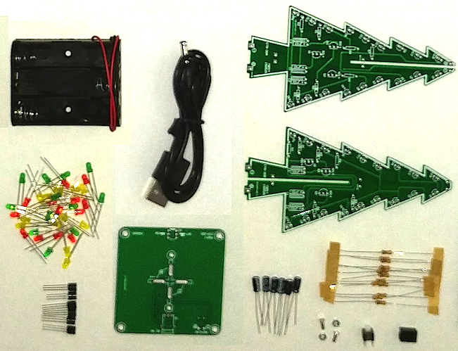
DIY solder kit. The flashing Christmas tree kit consists of three circuit boards, 37 LEDs that alternate flashing, and dual power sources.


 Lastly, insert the tree into the base PCB being careful to
observe the "+" and "-" designations on all three PCBs. Solder the tree
to the base PCB.
Lastly, insert the tree into the base PCB being careful to
observe the "+" and "-" designations on all three PCBs. Solder the tree
to the base PCB.
Discussions
Become a Hackaday.io Member
Create an account to leave a comment. Already have an account? Log In.
Newer kits come with RGB self blinking leds. So no need to add the oscillator circuit.
Are you sure? yes | no
I got my Christmas tree from Temu and the "instructions" were a 1/2 page and extremely poor. I made my way through it not realizing that the one half had the LED colors slightly different. Then I saw a statement that said these LED's were all the same and the position didn't matter.
When I turned it on only one half of the tree worked. I painstakingly checked everything over again and again. I scoured 3 or 4 different sites and their instruction sets and found that I had missed the wire connection over the power connector.
I also missed the arrows on the bottom of the tree parts and the base and had to desolder my tree from the base and rotate it 1/4 turn.
After this everything started working correctly.
There is only one thing that I'm confused about. It's the LED at the top of the tree. On board CTR-30A you have the + and - connections for the LED. On the other half there are 2 unmarked through holes. The directions are not really clear on how to deal with these.
Some photos I've seen make it look like they just have solder in them.
Did anyone bridge them to the pins on the other board?
Leave them alone?
Are you sure? yes | no
Nice overview. I built this kit last year
but would like to slow down the rate of change. Any suggestions for some trimmer pots instead of the static resistors to allow for such tweaking?
Are you sure? yes | no
Merry Christmas! Got it working with help from this post! I forgot to have the LEDs pointing out though! I got mine in 2019 and finished it yesterday (still within the Octave of Christmas), albeit two years late.
Are you sure? yes | no
Thank you for this set of instructions. I received no information with my kit from Ali and this saved me having to figure it all out on my own. I received the 10K resistors, but the other values were 150 ohms and R7 is 470 ohms. I also received 47uf caps. It's very bright, but nothing seems to be getting hot. I run it with 3 NiMh batteries and it's dimmer then it is with a USB adaptor.
Couple of suggestions. Prebend your LED's. I bent mine over a 1/8" thick wooden ruler clamped in a bench vice. Be sure you bend them in the correct direction, so they can be assembled as described above (long leg in square pad). I inserted the LED's and splayed the leads. Making sure none of the leads touched each other, I tested that section of the tree BEFORE soldering all of the LED's
Definitely assemble the base, with the battery holder, before you add the tree or you'll be cussing those little nuts.
I slid the 2 tree halves together and them placed them on the base before soldering them together. I tacked them to the base and then soldered the halves together. This ensured that the tree halves were perpendicular to each other.
Lastly, if you happen to not read the section describing the switch and put it on backwards, it still works, but the on/off positions are different than the diagram on the PCB, IE out is on and in is off. Have fun!
Are you sure? yes | no
@Mathijs Groothuis: The other board is being populated jut the same as the first one. The resistors are not exactly at the same place but are numbered the same. R7 is only on the first board. The LEDs are also in the same order.
BTW: I came across pictures on Aliexpress that were mirrored left to right.
Are you sure? yes | no
I see many trees with a whole different led order for the other tree half. On this page I only see the first half. All other trees on the internet have different order. Can you elaborate on this one? My green was too dim, so I changed it to your order, but I don't really understand what's the correct order when you take in account that certain resistors are meant for a certain color.
Are you sure? yes | no
Thank you for taking the time to post this. The little trees are a nice Xmas project and they do not come with instructions these days. There are dozens of vendors happy to take your money mind you.:-) I got a very Chinese version of the BOM but this is so much better. Bless you mate :-) I chnaged the current limiting resisitor all to 330 and the green are all still too dim for my tastes. I did not place the led's per instructions either :P
Are you sure? yes | no