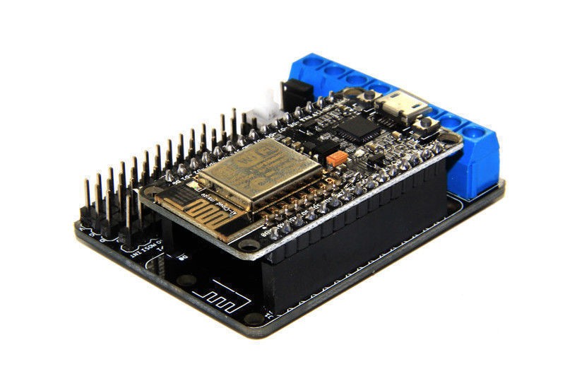
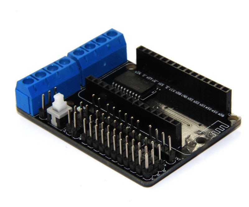
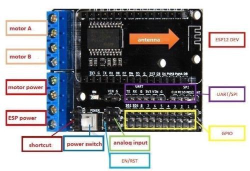
Connected small DC motor to test the Node MCU motor shield. The shield is based on the L293D quadruple high-current half-H drivers typically used to drive motors.

| Motor Shield | NodeMCU DevKit | GPIO | Purpose |
| D1 PWMA (Motor A) | D1 | 5 | Speed |
| D3 DIRA (Motor A) | D3 | 0 | Direction |
| D2 PWMA (Motor B) | D2 | 4 | Speed |
| D4 DIRB (Motor B) | D4 | 2 | Direction |
The test motor was a small DC motor from Jaycar electronics (Hobby Motor - Medium Torque YM2707). The operating voltage was first checked to ensure the motor isn't driven too hard by the motor shield. Operating volts of the little DC motor is 1.5 - 4.5V (with no load current of 0.25A).
Part of the test was to determine if the motor shield could drive the motor at different speeds. A 2-line LCD was also added to test the ability of the NodeMCU to drive both the motor shield and the LCD concurrently, something required of the final incubator controller solution. It also helped to show the changes in speed as they were being set by the NodeMCU program.
The LCD was connected D4 (GPIO 2) for SDA and D5 (GPIO 14) for SCL. The motor shield utilises D4 for the direction pin for Motor B. As Motor B was not in use this was not a problem. If two motors are to be used then the LCD SDA would be moved to an alternative pin. Also worth noting is the row of V pins in the breakout section of the shield are all 3.3V. To power the LCD the VIN breakout pin was used.
The test program used to drive the motor at different speeds is included below. The motor did not spin for anything less than 250 for the PWM value. One gotcha is to ensure analogWrite is used for writing to the PWMA pin and not digitalWrite. digitalWrite is used to write change the direction for the DIRA pin.
#include <Wire.h>
#include <LiquidCrystal_I2C.h>

LiquidCrystal_I2C lcd(0x27,16,2);

#define DIRA 0
#define PWMA 5

void setup() {
  // put your setup code here, to run once:
  Serial.begin(115200);
  Serial.println();
  Serial.println("Starting...");

  Serial.println("Initialising LCD...");
  lcd.init();                      // initialize the lcd

  // Print a message to the LCD.
  lcd.backlight();
  lcd.setCursor(0,0);
  lcd.print("Motor test");
  lcd.setCursor(0,1);
  lcd.print("Speed: 0");

//  Serial.println("Flashing internal LED");
//  pinMode(BUILTIN_LED, OUTPUT);
//  digitalWrite(BUILTIN_LED, LOW);
//  delay(100);
//  digitalWrite(BUILTIN_LED, HIGH);
//  delay(300);

  Serial.println("Preparing motor...");
  lcd.clear();
  lcd.setCursor(0,0);
  lcd.print("Preparing motor");
  pinMode(DIRA, OUTPUT);
  pinMode(PWMA, OUTPUT);

  analogWrite(PWMA,0);
  digitalWrite(DIRA,1);
  delay(5000);

  lcd.clear();
  Serial.println("Starting motor...");
  lcd.setCursor(0,0);
  lcd.print("Operating motor");
  lcd.setCursor(0,1);
  lcd.print("Speed: 5");
  analogWrite(PWMA,5);
  delay(5000);

  lcd.clear();
  lcd.setCursor(0,0);
  lcd.print("Operating motor");
  lcd.setCursor(0,1);
  lcd.print("Speed: 50");
  analogWrite(PWMA,50);
  delay(5000);

  lcd.clear();
  lcd.setCursor(0,0);
  lcd.print("Operating motor");
  lcd.setCursor(0,1);
  lcd.print("Speed: 100");
  analogWrite(PWMA,100);
  delay(5000);

  lcd.setCursor(0,1);
  lcd.print("Speed: 300");
  analogWrite(PWMA,300);
  delay(5000);

  lcd.clear();
  lcd.setCursor(0,0);
  lcd.print("Operating motor");
  lcd.setCursor(0,1);
  lcd.print("Speed: 1000");
  analogWrite(PWMA,1000);
  delay(3000);

  lcd.clear();
  lcd.setCursor(0,0);
  lcd.print("Slowing down");
  analogWrite(PWMA,0);
  delay(3000);

  lcd.clear();
  lcd.setCursor(0,0);
  lcd.print("Reversing motor");
  digitalWrite(DIRA,0);

  lcd.clear();
  lcd.setCursor(0,0);
  lcd.print("Operating motor (reverse)");
  lcd.setCursor(0,1);
  lcd.print("Speed: 50");
  analogWrite(PWMA,250);
  delay(3000);

}

void loop() {
  // put your main code here, to run repeatedly:

}
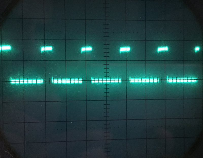
Measured the pulse coming out of the D1 pin on the NodeMCU DevKit board. This is feeding the L293D chip. Yes that is an old school CRO.

 Tony Kambourakis

Discussions
Become a Hackaday.io Member
Create an account to leave a comment. Already have an account? Log In.
Hello there! I havent seen many projects with the NodeMCU Motor Shield and I am looking for help :SSSSS
I am a teacher at 24 student class. Each one with a NodeMCU and Nodmecu Motor Shield trying to make a 2WD car run.
I think I have connected the pins properly and all the Digital OUTPUTS work well as long as I use them to ligh LEDS.
Anyway, at the point that we try to make the motors RUN it does NOT work at all.
I am using the D1 and D2 as PWM inputs and the D3 and D4 as rotation inputs but nothing works.
Simple code, make it run forward for 2 seconds backward for another 2 secondas.
The bridge for VI and VH is done.
I cannot figure out what I am doing wrong!!
Need HELPP :D
#define D0 16
#define D1 5 // I2C Bus SCL (clock)
#define D2 4 // I2C Bus SDA (data)
#define D3 0
#define D4 2 // Same as "LED_BUILTIN", but inverted logic
#define D5 14 // SPI Bus SCK (clock)
#define D6 12 // SPI Bus MISO #define D7 13 // SPI Bus MOSI
#define D8 15 // SPI Bus SS (CS)
#define D9 3 // RX0 (Serial console)
#define D10 1 // TX0 (Serial console)
void setup() {
pinMode(D1, OUTPUT); // PWM A
pinMode(D2, OUTPUT); // PWM B
pinMode(D3, OUTPUT); // Rotation A
pinMode(D4, OUTPUT); // Rotation B
}
// the loop function runs over and over again forever
void loop() {
analogWrite(D1, 1023); analogWrite(D2, 1023); digitalWrite(D3, HIGH); digitalWrite(D4, HIGH); delay(2000);
analogWrite(D1, 0); analogWrite(D2, 0); digitalWrite(D3, LOW); digitalWrite(D4, LOW); delay(2000); }
Any Idea What could be wrong?
Are you sure? yes | no
Question from a newbie. I would like to use the Motor Shield with several sensors to control my garage door. Is it possible to use the motor input\outputs to control the garage circuit to trigger the open\close of the garage. I want to simulate a relay shield but hoping to use the motor shield without adding another component. If possible, would appreciate any wiring \ coding tips. Thanks.
Are you sure? yes | no
For the final unit I will be using a 12V DC adapter that will supply both the NodeMCU/motor shield/LCD via regulated 5V and provide 12V DC to the motor (via the motor shield VM input.
Are you sure? yes | no
Nice use of the VIN PIN to get 5 Volts for the LCD. Now I have to go back and check how you powered it with the original LCD experiment.
Are you sure? yes | no
You pulled 5V out of thin air which reconciles with my view that the DEV board only support 3.3V. All good.
Are you sure? yes | no
It was powered via USB. That seems to put 5V onto the Vin pin which I thought was an input but perhaps when plugged into USB is an output. Wish there was a devkit data sheet.
Are you sure? yes | no
Could this be used to power a servo to open the smartletterbox so an owner could retireve the letters by remote control (mobile) or even location/proximity control? What about a 60 video of the experiment (not sure whether the site supports that)? What makes a motor-shield neccesary above a standard dev board? (Why does the board have a Driven chip: L293D?))
Are you sure? yes | no
Or is it the fact that the motor shield allows me to drive a motor up to
36V that makes it significant where a dev board might allow me
~3.3V?
Are you sure? yes | no
The L293D is only for driving DC motors or stepper motors (typically at much higher voltage and current). Servos can be driven directly from the output pin of the NodeMCU and don't need the 293. The motor shield provides the L293D (plus some supporting components) and breaks out the various NodeMCU pins plus some hefty motor connectors. From the L293D data sheet:
"The Device is a monolithic integrated high voltage, high current four channel driver designed to accept standard DTL or TTL logic levels and drive inductive loads (such as relays solenoides, DC and stepping motors) and switching power transisters. To simplify use as two bridges each pair of channels is equipped with an enable input. A separate supply input is provided for the logic, allowing operation at a lower voltage and internal clamp diodes are included. This device is suitable for use in switching applications at frequencies up to 5 kHz."
Are you sure? yes | no