 Tony Kambourakis
TBD
0%
0%
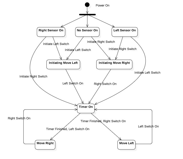
Incubator Controller
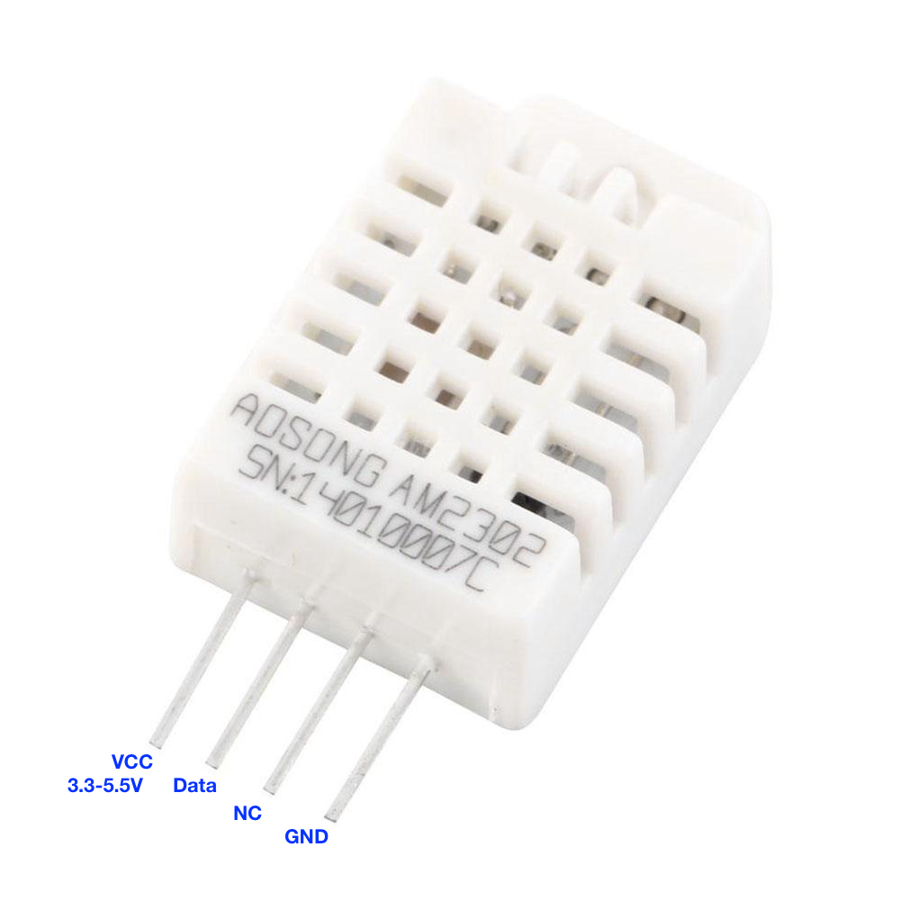
Controls the periodic tilting of the egg tray, measuring and displaying the temperature and humidity with alerting via push notification
Become a Hackaday.io member
Already have an account? Log in.
Just one more thing
To make the experience fit your profile, pick a username and tell us what interests you.
Pick an awesome username
hackaday.io/
Your profile's URL: hackaday.io/username. Max 25 alphanumeric characters.
Pick a few interests
Projects that share your interests
People that share your interests


 Lasith Ishan
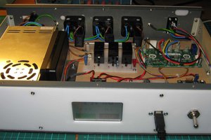
 Mark Atherton
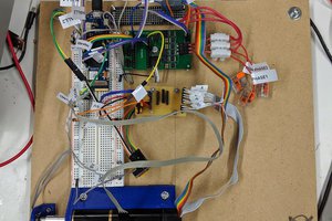
 Simon Trendel
 Tom Van den Bon
Very interesting
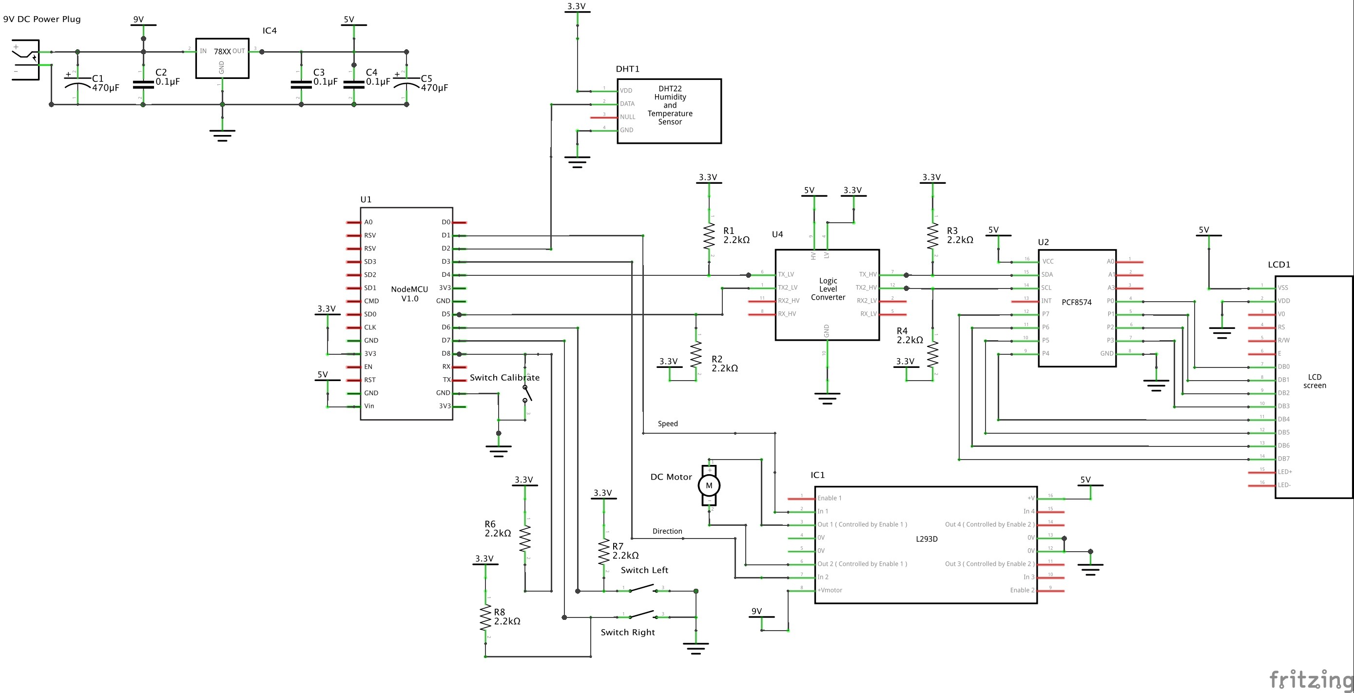
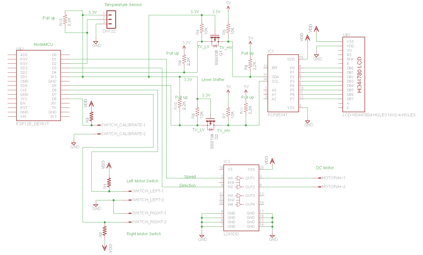
Your fritzing circuit shows just a block for the level converter where your regular circuit shows actual components. With prices of say a 4 channel levelconverter being around 30 cts, I would advise anybody to just get the premade module. Same goes for the PCF8574, get a premade module that will slot right in the pins of your lcd. better yet, get an lcd that already has that module attached. (But I think you already advise that in your component list)
I know many people use the LCD without levelshifter, I don't risk it though
Your Fritzing circuit looks indeed very clear. I however found it very cumbersome to use. Only using it for PCB's using sPlan for circuits.
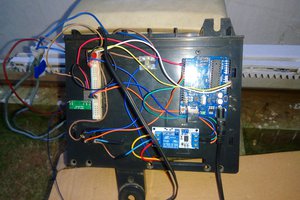
Was wondering abt your eggturner. You have a 12 DC motor. most commercial eggturners I know use 110-220Volt. Judging from your pics you constructed one yourself? If so, I'd be most interested to see more details.
As we are about a year down the line... did it work as you expected? anything you would change?