-
Tray tilting logic
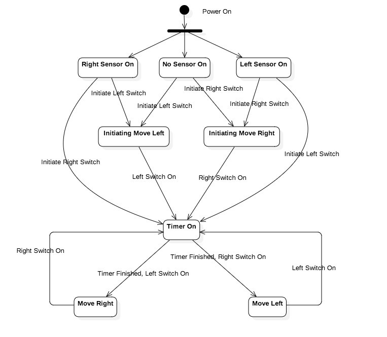
12/13/2016 at 00:42 • 0 commentsThe egg tray must tilt every 4 hours. When the incubator controller is switched on it must determine the current position of the tray. If either motor switch sensors are activated it implies the tray is in the middle. As such it will activate the motor to the default position (LEFT) until the LEFT switch is activated and start the timer. If a switch is already active it will leave it in that position and start the timer. The following state diagram illustrates this logic.
![]()
-
DHT22 Pins
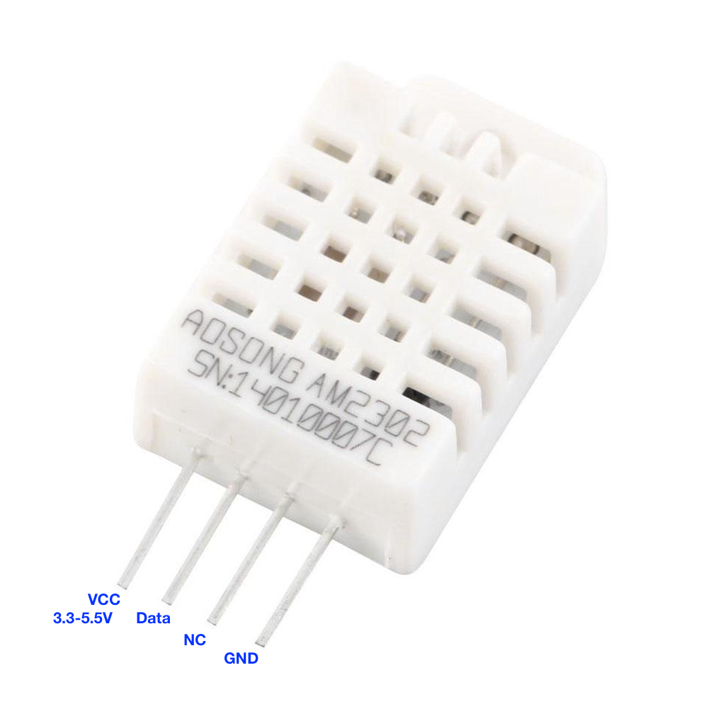
12/06/2016 at 05:12 • 0 commentsThe DHT22 4-pin package comprises the following PIN assignments
![]()
-
Fritzing Schematic
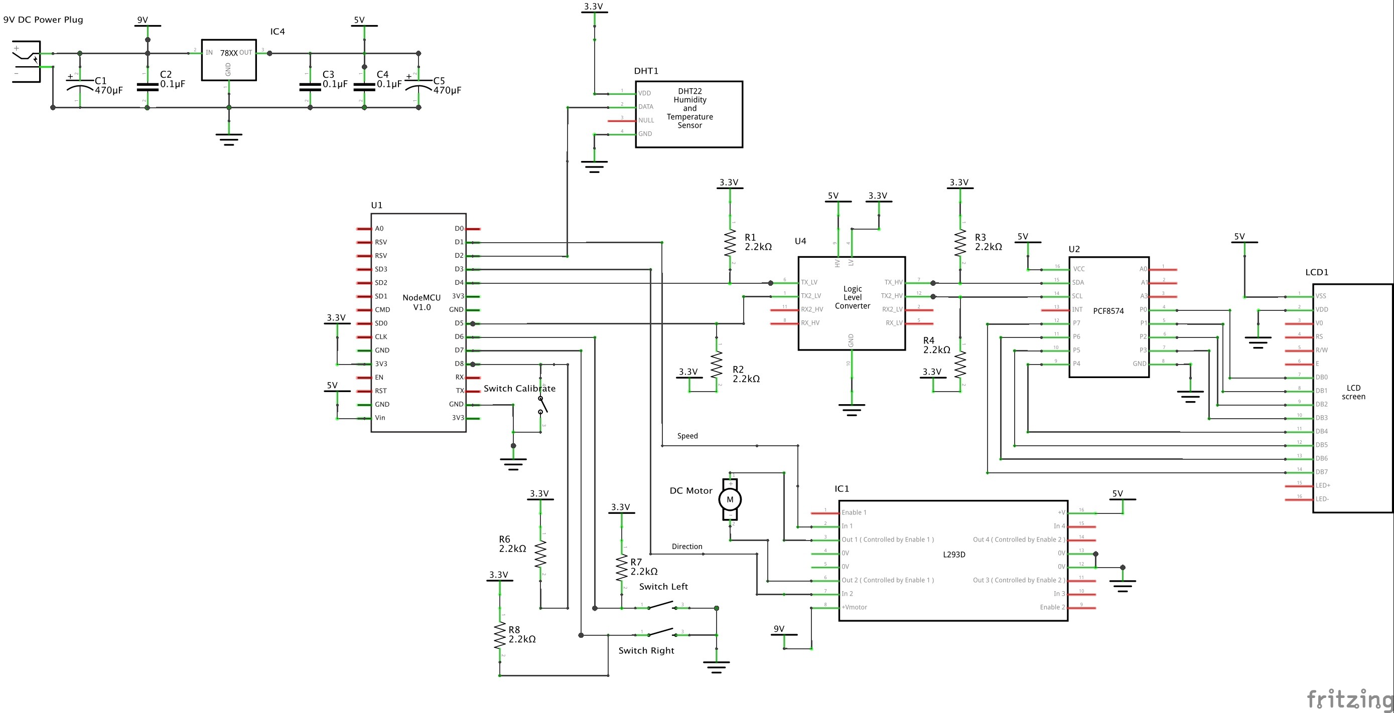
02/28/2016 at 13:07 • 0 comments![]()
-
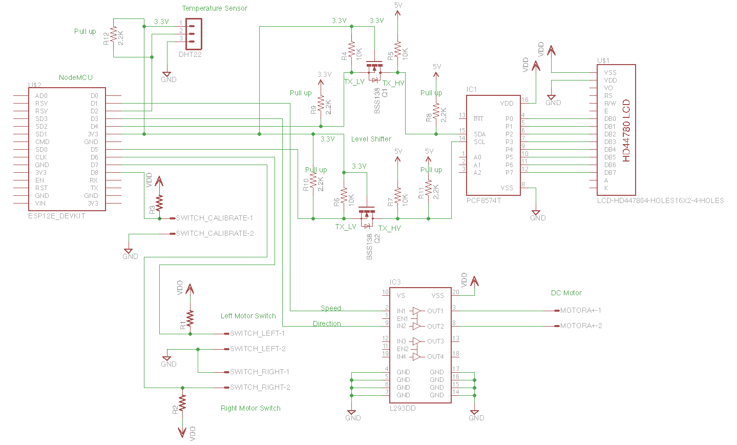
Schematic
01/28/2016 at 13:30 • 0 comments![]()
-
Level Shifting and SDA/SCL Pull Ups
01/26/2016 at 03:00 • 0 commentsThe ESP8266 (ESP-12E), the core of the NodeMCU devkit, requires a 3.3V supply. The GPIO pins also supposedly operate at 3.3V logic levels. This can be confirmed with the NodeMCU DevKit official documentation:
不得对开发板输入超过 5V 以上的电源电压,也不得将开发板 GPIO 直接连接到 5V 电平的外设上。如果需要连接,需要电平转换电路,否则可能造成不可逆转的损坏。
The board shall not enter more than 5V supply voltage, nor will board GPIO directly connected to 5V level peripherals. If you need to connect
Then, we need to level conversion circuit, or it may cause irreversible damage.The NodeMCU documentation is light on but it seems that the board is typically supplied with 5V either via the VIN pin or the USB socket. Supplying power directly to the 3.3V pins also powers up the MCU but driving the LCD that way results in a very dim LCD output even at maximum brightness setting with a current consumption by the LCD of around 6 mA. When powered at 5V the LCD consumes around 20 mA.
The required supply voltage for the LCDs (4-line and 2-line) I have been using state 5V even though they comprise the HDD44780, which requires a supply voltage of 2.7V to 5.5V, and the I2C's PCA8574, which can operates at 2.3V to 5.5V (HIGH-level input voltage is 0.7VDD min and 5.5V max).
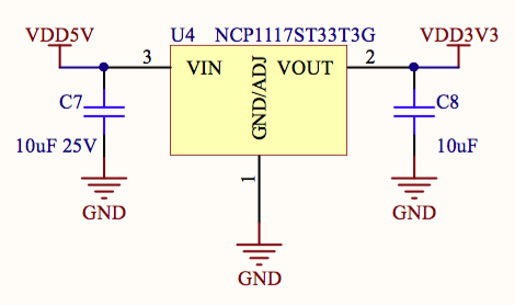
The NodeMCU DevKit includes an NCP1117 regulator that takes 5V in and supplies the ESP-12E with 3.3V.
![]()
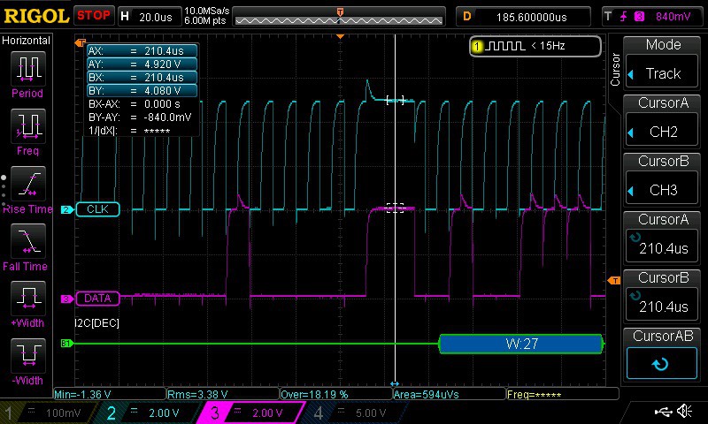
Interestingly if the NodeMCU is powered by 5V and drives the LCD via I2C directly the SDA/SDCL levels measure around 4V! At this level it satisfies the 0.7VDD requirement of the PC8574 (0.7 x 5 = 3.5V) on the LCD. In this case the LCD is supplied with 5V off the power supply. As seen in the scope image below, the SCL high level is 4.92V and the SDA (DATA) high level is 4.08V.
![]()
How does that Node MCU GPIO output get to 4.92V when the ESP-12E is powered by 3.3V? Why is the SDA level only 4.08V and the SCL level at 4.92V?
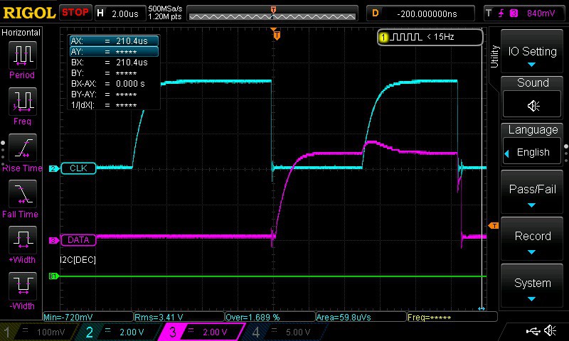
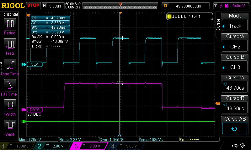
I suspect it has something to do with the PCA8574 pulling high perhaps due to an internal pull up resistor either on the NodeMCU or 8574. The slow rise time of the SCL and DATA signals also indicate the use of an internal pull up resistor as an external pull up had not been used yet. The scope shot below shows the slow rise time.
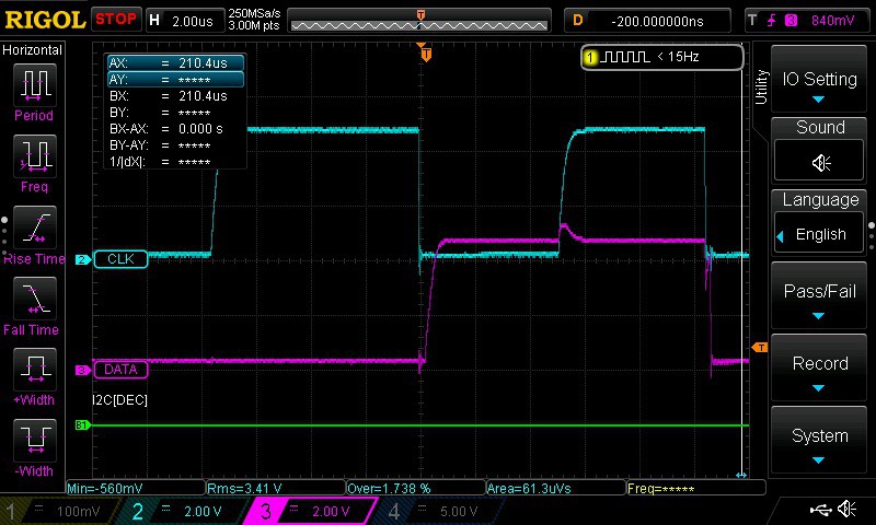
Adding a pull up resistor (2.2 kΩ) improves the slow rise time as seen in the next shot.![]()
![]()
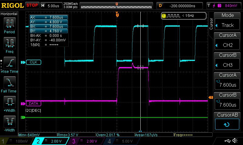
A level shifter (Duinotech Logic Level Converter Module from Jaycar which is a rebadged SparkFun module) was also introduced to increase the voltage levels of the SDA and SCL signals. The scope shot below shows the SCL at 4.8V and the SDA at 4.76V.
![]()
There isn't much difference in what is displayed on the LCD with the level shifter. The SDA/SCL levels on the MCU side of the level shifter have dropped back to 3.3V. Pull up resistors were also added to the MCU side of SDA/SCL.
![]()
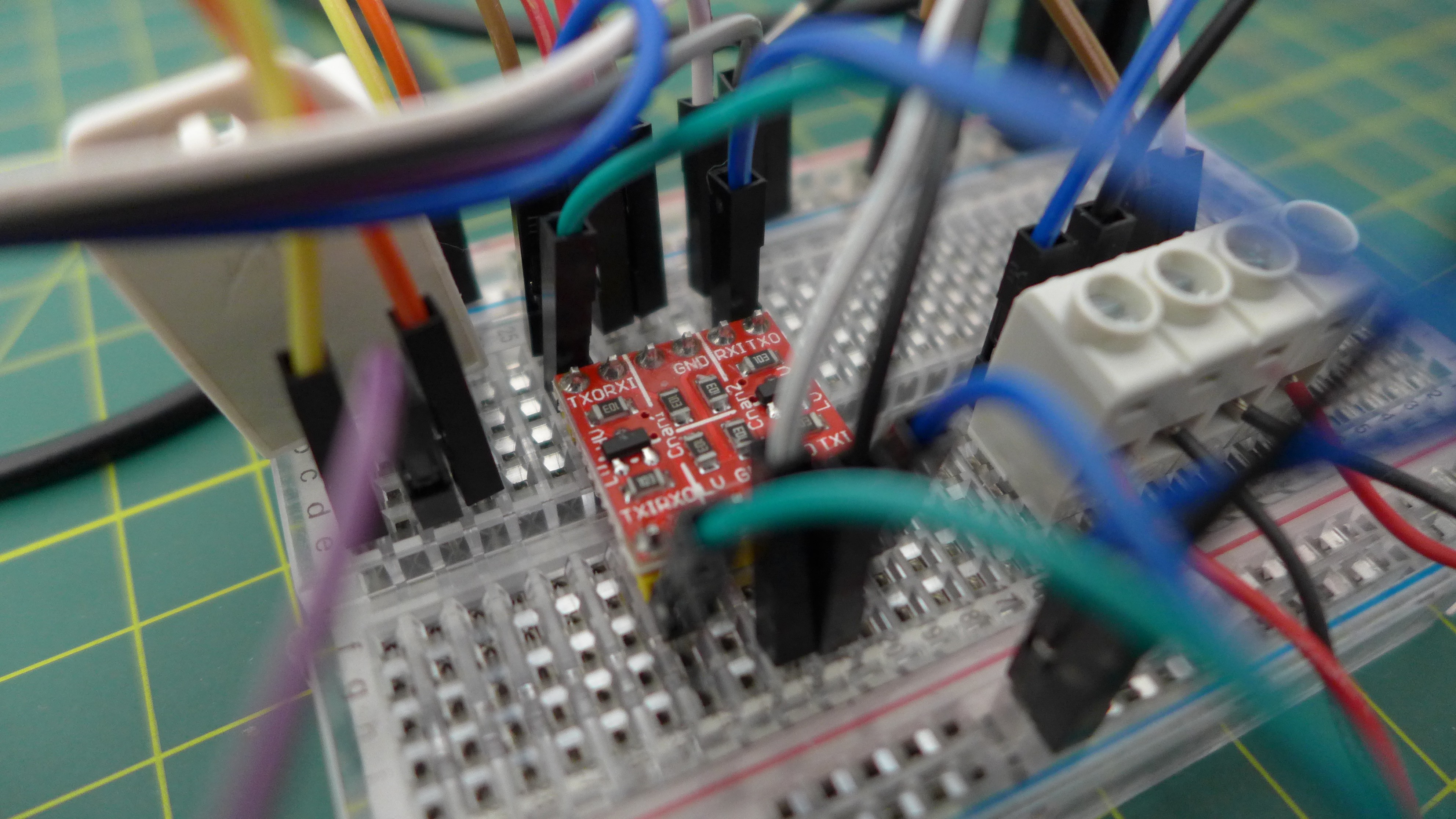
The level shifter:
![]()
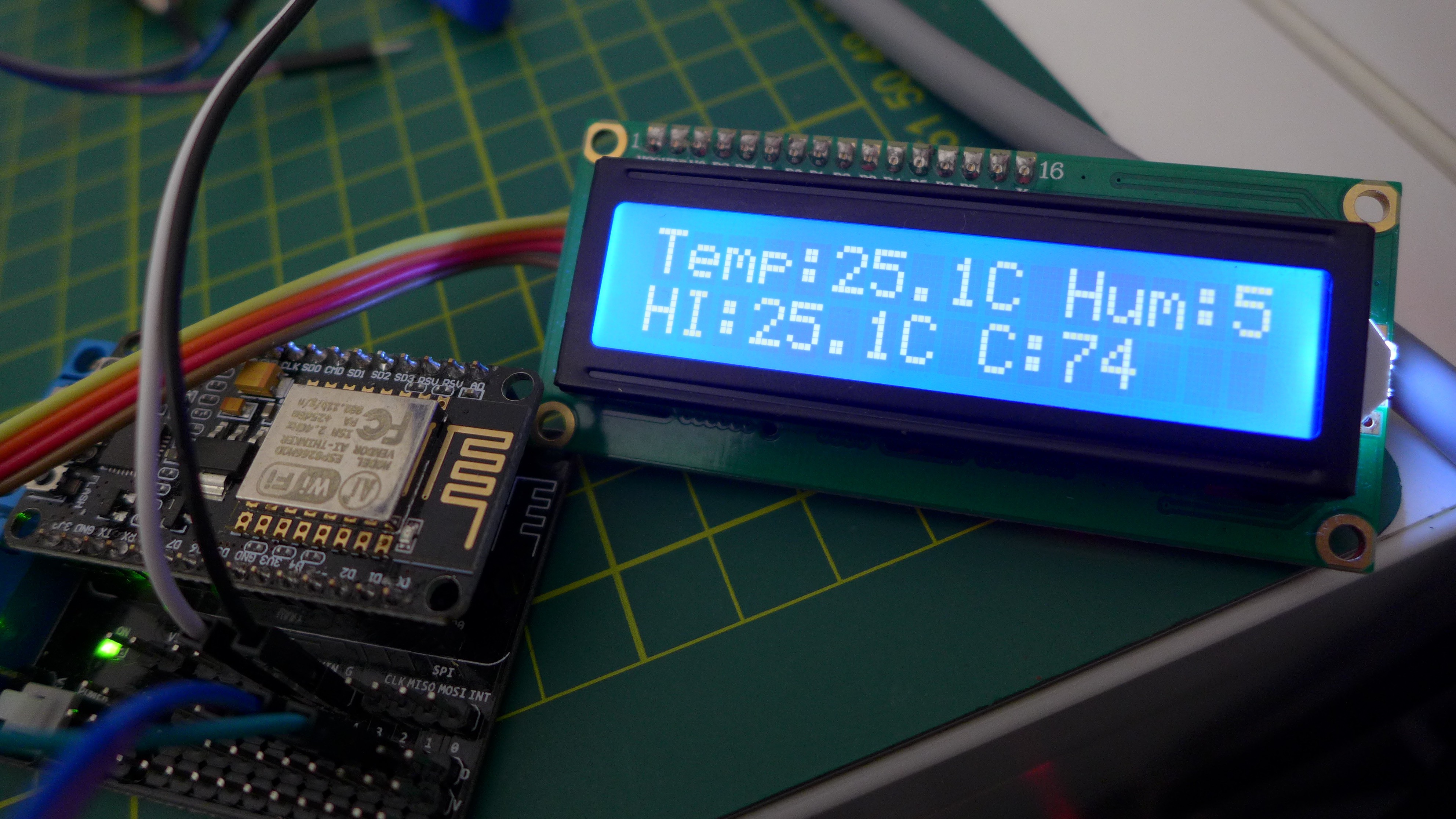
Reading temperature and humidity (and heat index) from the DHT22 and displaying on LCD (along with counter "C") - yep, the humidity is cut off. I'll be using the larger 4-line display.
![]()
-
Noisy DC Motor
01/09/2016 at 15:56 • 2 commentsRan some tests with both a desktop power supply (3V-12V@1.5A) and a power pack (12V@1A) with the motor shield. The noise generated by the small DC motor is significant across both supplies. Both supplies were fed into my own 12V to 5V regulator circuit shown below.
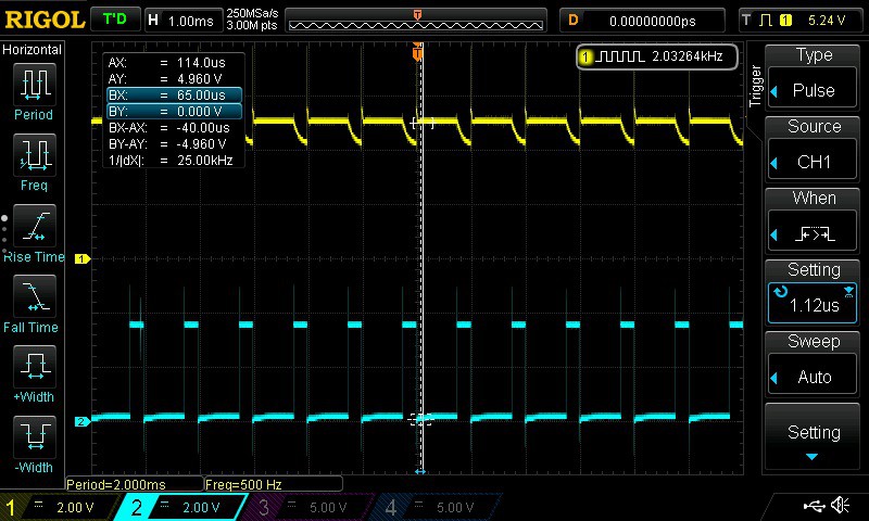
![]() Using the desktop power supply the CH1 (Yellow) trace below shows the 5 V rail along with the CH2 (Blue) trace showing the NodeMCU D1 (GPIO 5) PWM signal (controls speed, see this post).
Using the desktop power supply the CH1 (Yellow) trace below shows the 5 V rail along with the CH2 (Blue) trace showing the NodeMCU D1 (GPIO 5) PWM signal (controls speed, see this post). ![]()
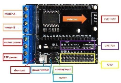
This is a concern given the motor shield was configured for separate supplies between the MCU and motor using the shortcut jumper (see motor shield diagram). The MCU was being powered using USB and the motor was powered using the external power supply.
I noticed that when I powered the MCU from the power supply (either the desktop supply or the power pack) the LCD was dim and the motor wouldn't run for anything less than a high PWM signal. Something else to investigate.
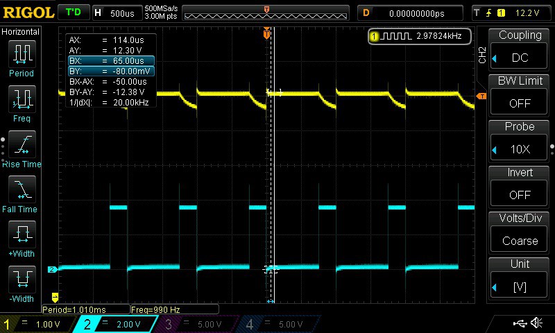
The 12 V rail didn't fair much better than the 5 V rail.
![]()
The LCD was also being powered from the VIN pin on the motor shield (that maps to the 5V Vin pin on the NodeMCU Dev Kit). VIN is supposed to support 5V. Reports indicate that the Dev Kit has a 5V to 3.3V regulator circuit given the ESP8266 requires 3.3V.
Next steps:
- check the current consumption across the MCU, LCD and motor
- power just the MCU and LCD with power supplies without the motor shield to see if it is still dim
- try alternative motor shield
- try alternative motor
-
NodeMCU DevKit Pins
12/20/2015 at 14:32 • 0 comments![]()
-
Node MCU Motor Shield
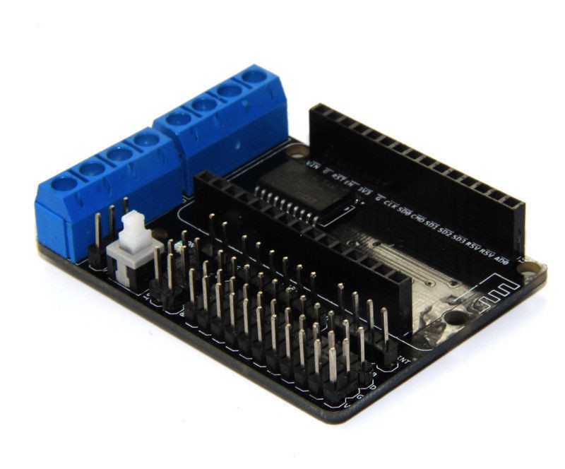
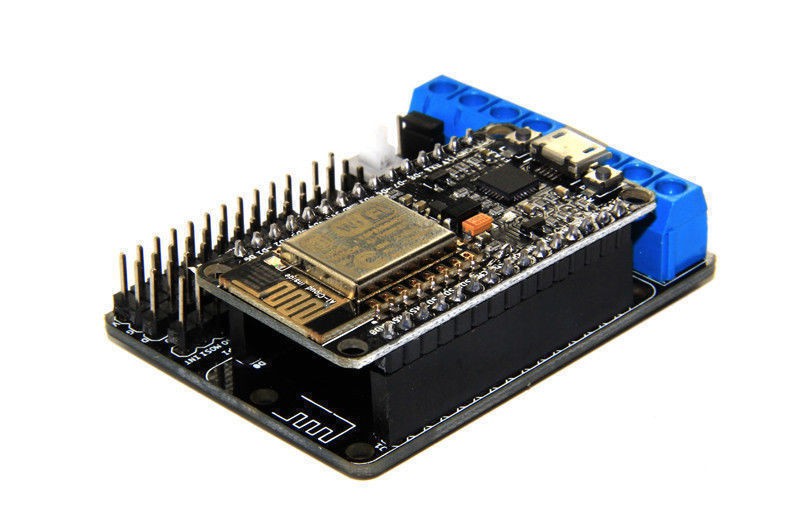
12/20/2015 at 13:38 • 9 commentsConnected small DC motor to test the Node MCU motor shield. The shield is based on the L293D quadruple high-current half-H drivers typically used to drive motors.
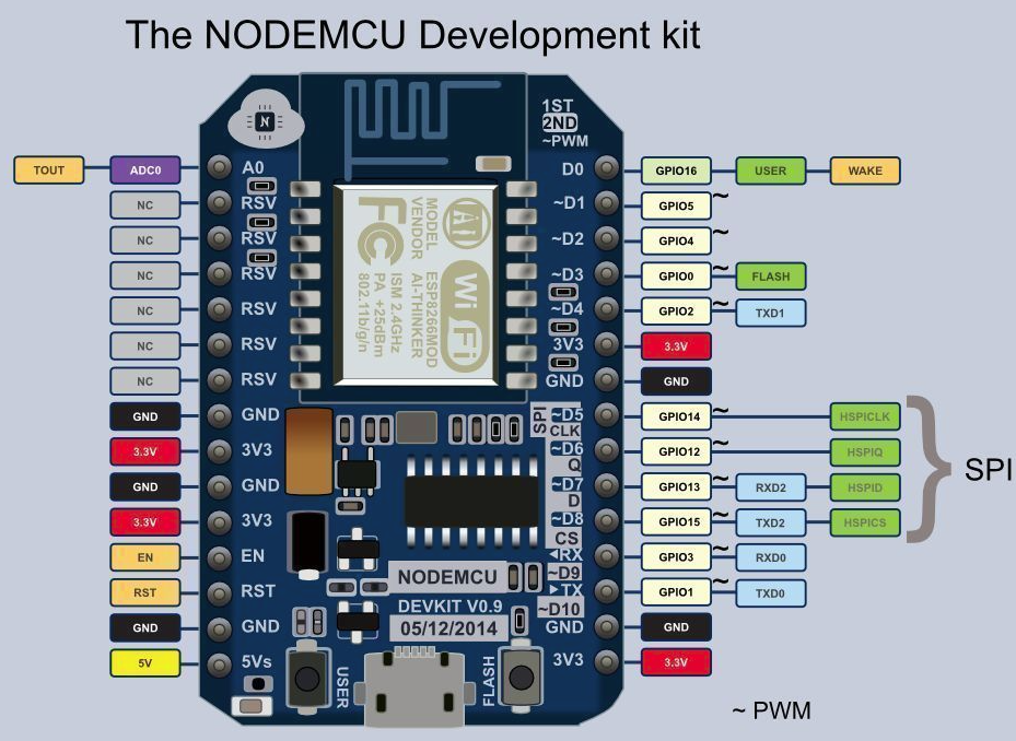
The NodeMCU DevKit docks onto the shield and utilises some of the GPIO ports to control the motor. The motor shield supports two motors. Only one will be utilised for the incubator. The shield utilises the following pins to operate as specified in the user guide:
Motor Shield NodeMCU DevKit GPIO Purpose D1 PWMA (Motor A) D1 5 Speed D3 DIRA (Motor A) D3 0 Direction D2 PWMA (Motor B) D2 4 Speed D4 DIRB (Motor B) D4 2 Direction The test motor was a small DC motor from Jaycar electronics (Hobby Motor - Medium Torque YM2707). The operating voltage was first checked to ensure the motor isn't driven too hard by the motor shield. Operating volts of the little DC motor is 1.5 - 4.5V (with no load current of 0.25A).
Part of the test was to determine if the motor shield could drive the motor at different speeds. A 2-line LCD was also added to test the ability of the NodeMCU to drive both the motor shield and the LCD concurrently, something required of the final incubator controller solution. It also helped to show the changes in speed as they were being set by the NodeMCU program.
The LCD was connected D4 (GPIO 2) for SDA and D5 (GPIO 14) for SCL. The motor shield utilises D4 for the direction pin for Motor B. As Motor B was not in use this was not a problem. If two motors are to be used then the LCD SDA would be moved to an alternative pin. Also worth noting is the row of V pins in the breakout section of the shield are all 3.3V. To power the LCD the VIN breakout pin was used.
The test program used to drive the motor at different speeds is included below. The motor did not spin for anything less than 250 for the PWM value. One gotcha is to ensure analogWrite is used for writing to the PWMA pin and not digitalWrite. digitalWrite is used to write change the direction for the DIRA pin.
#include <Wire.h>
#include <LiquidCrystal_I2C.h>

LiquidCrystal_I2C lcd(0x27,16,2);

#define DIRA 0
#define PWMA 5

void setup() {
  // put your setup code here, to run once:
  Serial.begin(115200);
  Serial.println();
  Serial.println("Starting...");

  Serial.println("Initialising LCD...");
  lcd.init();                      // initialize the lcd

  // Print a message to the LCD.
  lcd.backlight();
  lcd.setCursor(0,0);
  lcd.print("Motor test");
  lcd.setCursor(0,1);
  lcd.print("Speed: 0");

//  Serial.println("Flashing internal LED");
//  pinMode(BUILTIN_LED, OUTPUT);
//  digitalWrite(BUILTIN_LED, LOW);
//  delay(100);
//  digitalWrite(BUILTIN_LED, HIGH);
//  delay(300);

  Serial.println("Preparing motor...");
  lcd.clear();
  lcd.setCursor(0,0);
  lcd.print("Preparing motor");
  pinMode(DIRA, OUTPUT);
  pinMode(PWMA, OUTPUT);

  analogWrite(PWMA,0);
  digitalWrite(DIRA,1);
  delay(5000);

  lcd.clear();
  Serial.println("Starting motor...");
  lcd.setCursor(0,0);
  lcd.print("Operating motor");
  lcd.setCursor(0,1);
  lcd.print("Speed: 5");
  analogWrite(PWMA,5);
  delay(5000);

  lcd.clear();
  lcd.setCursor(0,0);
  lcd.print("Operating motor");
  lcd.setCursor(0,1);
  lcd.print("Speed: 50");
  analogWrite(PWMA,50);
  delay(5000);

  lcd.clear();
  lcd.setCursor(0,0);
  lcd.print("Operating motor");
  lcd.setCursor(0,1);
  lcd.print("Speed: 100");
  analogWrite(PWMA,100);
  delay(5000);

  lcd.setCursor(0,1);
  lcd.print("Speed: 300");
  analogWrite(PWMA,300);
  delay(5000);

  lcd.clear();
  lcd.setCursor(0,0);
  lcd.print("Operating motor");
  lcd.setCursor(0,1);
  lcd.print("Speed: 1000");
  analogWrite(PWMA,1000);
  delay(3000);

  lcd.clear();
  lcd.setCursor(0,0);
  lcd.print("Slowing down");
  analogWrite(PWMA,0);
  delay(3000);

  lcd.clear();
  lcd.setCursor(0,0);
  lcd.print("Reversing motor");
  digitalWrite(DIRA,0);

  lcd.clear();
  lcd.setCursor(0,0);
  lcd.print("Operating motor (reverse)");
  lcd.setCursor(0,1);
  lcd.print("Speed: 50");
  analogWrite(PWMA,250);
  delay(3000);

}

void loop() {
  // put your main code here, to run repeatedly:

}
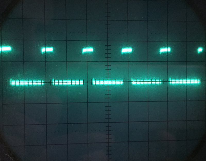
Measured the pulse coming out of the D1 pin on the NodeMCU DevKit board. This is feeding the L293D chip. Yes that is an old school CRO.
![]()
-
Driving LCD with I2C
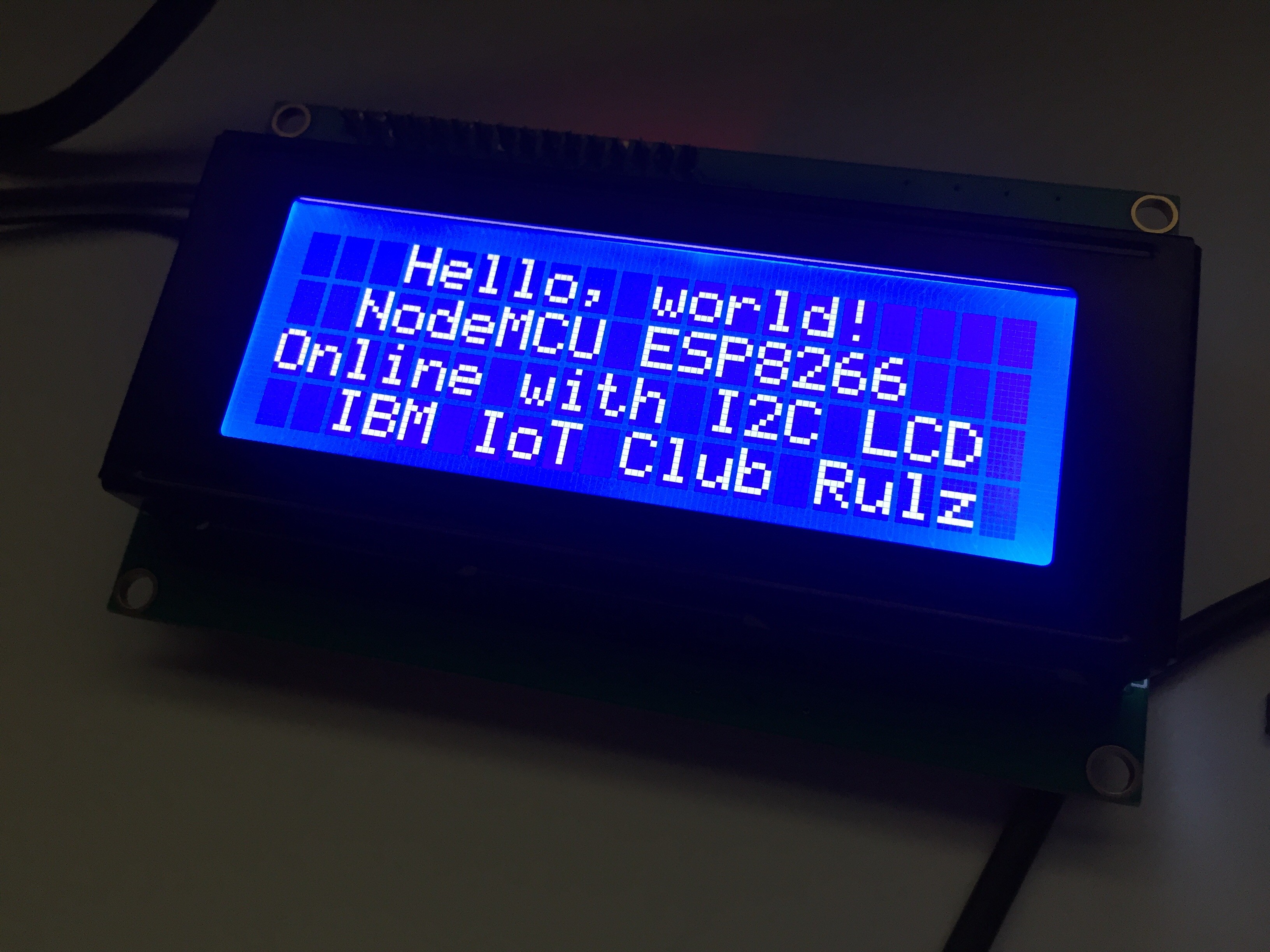
12/19/2015 at 16:17 • 3 commentsEstablished I2C link to TWI 2004 204 20x4 LCD module from the ESP8266. The ESP8266 port for Arduino thankfully includes an I2C implementing in the Wire library.
The only additional library required for working with the LCD is LiquidCrystal_I2C by Marco Schwartz (Version 1.1.0). This is accessible via the Arduino IDE Library Manager.
![]()
A slight modification of this library is also required to map it to the NodeMCU Amica DevKit pins that I connected the LCD to. Once the library is installed open the LiquidCrystal_I2C.cpp file located in the libraries folder. On a mac it is located in
~/Documents/Arduino/libraries/LiquidCrystal_I2C
The necessary update is included below:
void LiquidCrystal_I2C::init_priv()
{
	Wire.begin(2,14); // was originally Wire.begin();
	_displayfunction = LCD_4BITMODE | LCD_1LINE | LCD_5x8DOTS;
	begin(_cols, _rows);
}
2, 14 represent GPIO2 and GPIO14. On the NodeMCU Amica they are physically pins D4 and D5.The code to display text on a 4 line display is as follows:
#include <Wire.h>
#include <LiquidCrystal_I2C.h>

LiquidCrystal_I2C lcd(0x27,20,4);  // set the LCD address to 0x27 for a 20 chars and 4 line display

void setup()
{
  lcd.init();                      // initialize the lcd
  lcd.init();
  // Print a message to the LCD.
  lcd.backlight();
  lcd.setCursor(3,0);
  lcd.print("Hello, world!");
  lcd.setCursor(2,1);
  lcd.print("NodeMCU ESP8266");
   lcd.setCursor(0,2);
  lcd.print("Online with I2C LCD");
   lcd.setCursor(2,3);
  lcd.print("IBM IoT Club Rulz");
}


void loop()
{
}
The initialisation of the LiquidCrystal_I2C object includes a HEX address of the LCD I2C controller that is attached to he back of the LCD. It can be discovered using scanner code by Nick Gammon (site includes a great primer on I2C) . The code is included below:
// I2C Scanner
// Written by Nick Gammon
// Date: 20th April 2011

#include <Wire.h>

void setup() {
  Serial.begin (115200);

  // Leonardo: wait for serial port to connect
  while (!Serial)
    {
    }

  Serial.println ();
  Serial.println ("I2C scanner. Scanning ...");
  byte count = 0;

  Wire.begin();
  for (byte i = 8; i < 120; i++)
  {
    Wire.beginTransmission (i);
    if (Wire.endTransmission () == 0)
      {
      Serial.print ("Found address: ");
      Serial.print (i, DEC);
      Serial.print (" (0x");
      Serial.print (i, HEX);
      Serial.println (")");
      count++;
      delay (1);  // maybe unneeded?
      } // end of good response
  } // end of for loop
  Serial.println ("Done.");
  Serial.print ("Found ");
  Serial.print (count, DEC);
  Serial.println (" device(s).");
}  // end of setup

void loop() {}
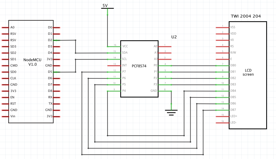
The schematic
![]()
Incubator Controller
Controls the periodic tilting of the egg tray, measuring and displaying the temperature and humidity with alerting via push notification
 Tony Kambourakis
 Using the desktop power supply the CH1 (Yellow) trace below shows the 5 V rail along with the CH2 (Blue) trace showing the NodeMCU D1 (GPIO 5) PWM signal (controls speed, see
 The NodeMCU DevKit docks onto the shield and utilises some of the GPIO ports to control the motor. The motor shield supports two motors. Only one will be utilised for the incubator. The shield utilises the following pins to operate as specified in the