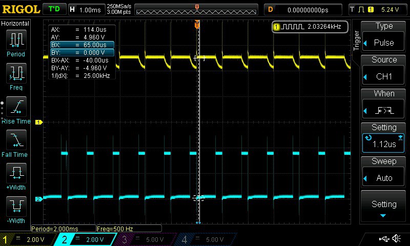
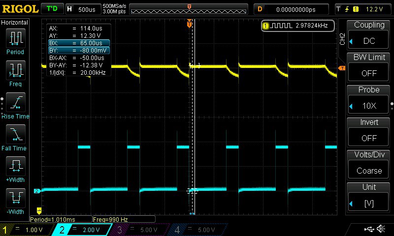
Ran some tests with both a desktop power supply (3V-12V@1.5A) and a power pack (12V@1A) with the motor shield. The noise generated by the small DC motor is significant across both supplies. Both supplies were fed into my own 12V to 5V regulator circuit shown below.
 Using the desktop power supply the CH1 (Yellow) trace below shows the 5 V rail along with the CH2 (Blue) trace showing the NodeMCU D1 (GPIO 5) PWM signal (controls speed, see this post).

This is a concern given the motor shield was configured for separate supplies between the MCU and motor using the shortcut jumper (see motor shield diagram). The MCU was being powered using USB and the motor was powered using the external power supply.
I noticed that when I powered the MCU from the power supply (either the desktop supply or the power pack) the LCD was dim and the motor wouldn't run for anything less than a high PWM signal. Something else to investigate.
The 12 V rail didn't fair much better than the 5 V rail.

The LCD was also being powered from the VIN pin on the motor shield (that maps to the 5V Vin pin on the NodeMCU Dev Kit). VIN is supposed to support 5V. Reports indicate that the Dev Kit has a 5V to 3.3V regulator circuit given the ESP8266 requires 3.3V.
Next steps:
- check the current consumption across the MCU, LCD and motor
- power just the MCU and LCD with power supplies without the motor shield to see if it is still dim
- try alternative motor shield
- try alternative motor
 Tony Kambourakis
Discussions
Become a Hackaday.io Member
Create an account to leave a comment. Already have an account? Log In.
Current consumption was well within he limits of the power supply.
I added some capacitors across the DC motors terminals and that reduced the noise. The larger motor to be used on the incubator has less noise coming out of it anyway.
The LCD dimming was due to faulty wires. The LCD would flicker as I touched the wires.
Are you sure? yes | no
Good news. By what measurement is the DC power:noise ratio observed?
Are you sure? yes | no