TBD
Incubator Controller
Controls the periodic tilting of the egg tray, measuring and displaying the temperature and humidity with alerting via push notification
Controls the periodic tilting of the egg tray, measuring and displaying the temperature and humidity with alerting via push notification
To make the experience fit your profile, pick a username and tell us what interests you.
We found and based on your interests.
TBD
DFR0063_v1.2_Schematic.pdfDF Robot 2-line LCD display with I2C piggy back board schematic diagramAdobe Portable Document Format - 42.63 kB - 01/26/2016 at 15:39 |
|
|
NODEMCU_DEVKIT_V1.0.PDFNodeMCU DevKit 1.0 (with ESP-12E) official schematic diagramsAdobe Portable Document Format - 843.68 kB - 01/26/2016 at 15:23 |
|
|
PCA8574_PCA8574A.pdfThe PCA8574A is the key component on the piggyback board attached to the LCD enabling I2C.Adobe Portable Document Format - 1011.01 kB - 01/26/2016 at 03:42 |
|
|
NODEMCU-DEVKIT-V1.0-INSTRUCTION-EN.pdfOffical NodeMCU DevKit 1.0 documentation. I added a google translate of the last page as the Page 2 is in Chinese.Adobe Portable Document Format - 228.12 kB - 01/26/2016 at 03:10 |
|
|
SGS-L293D_motor_driver_IC.pdfL293D motor driver datasheetapplication/pdf - 80.68 kB - 12/22/2015 at 14:30 |
|
|
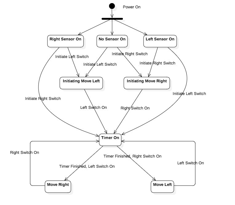
The egg tray must tilt every 4 hours. When the incubator controller is switched on it must determine the current position of the tray. If either motor switch sensors are activated it implies the tray is in the middle. As such it will activate the motor to the default position (LEFT) until the LEFT switch is activated and start the timer. If a switch is already active it will leave it in that position and start the timer. The following state diagram illustrates this logic.
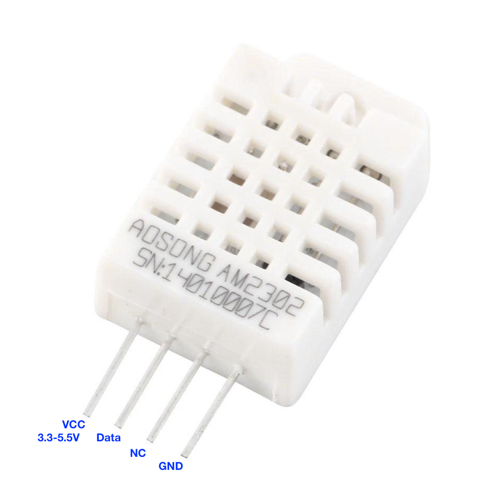
The DHT22 4-pin package comprises the following PIN assignments
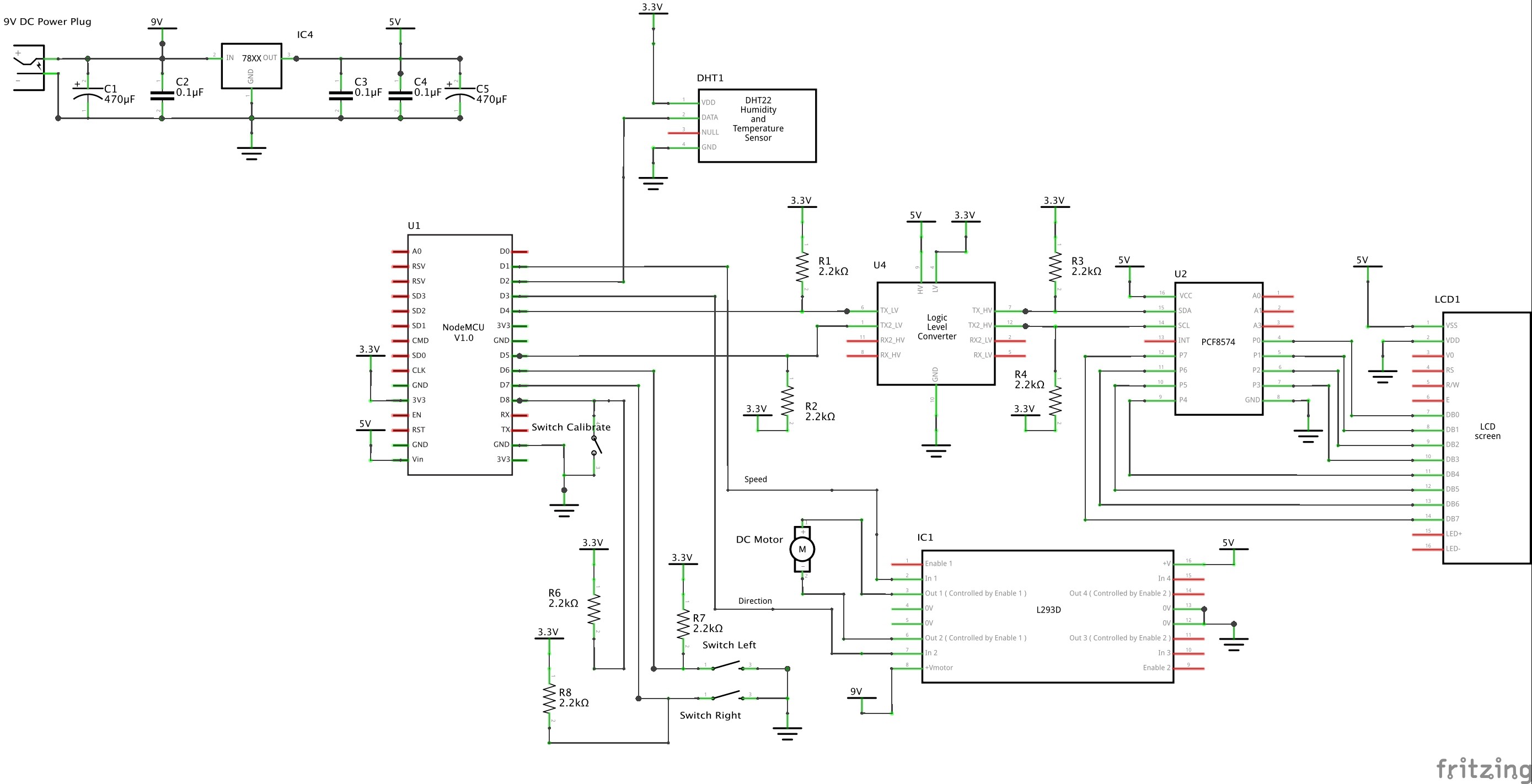
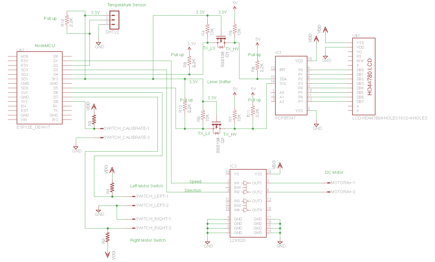
The ESP8266 (ESP-12E), the core of the NodeMCU devkit, requires a 3.3V supply. The GPIO pins also supposedly operate at 3.3V logic levels. This can be confirmed with the NodeMCU DevKit official documentation:
不得对开发板输入超过 5V 以上的电源电压,也不得将开发板 GPIO 直接连接到 5V 电平的外设上。如果需要连接,需要电平转换电路,否则可能造成不可逆转的损坏。
The board shall not enter more than 5V supply voltage, nor will board GPIO directly connected to 5V level peripherals. If you need to connectRead more »
Then, we need to level conversion circuit, or it may cause irreversible damage.
Ran some tests with both a desktop power supply (3V-12V@1.5A) and a power pack (12V@1A) with the motor shield. The noise generated by the small DC motor is significant across both supplies. Both supplies were fed into my own 12V to 5V regulator circuit shown below.
Read more »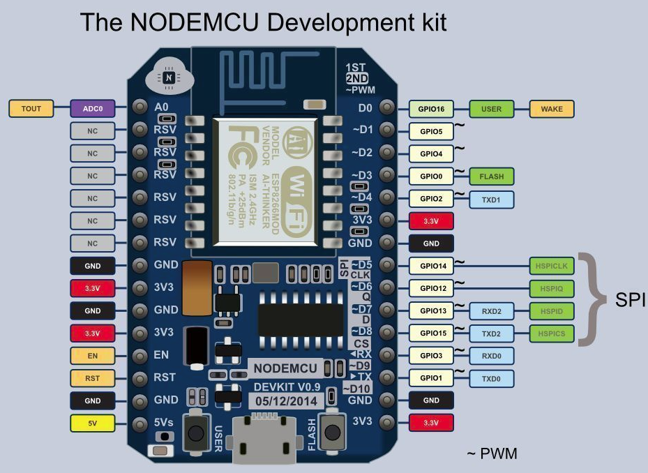
Connected small DC motor to test the Node MCU motor shield. The shield is based on the L293D quadruple high-current half-H drivers typically used to drive motors.
Read more »Established I2C link to TWI 2004 204 20x4 LCD module from the ESP8266. The ESP8266 port for Arduino thankfully includes an I2C implementing in the Wire library.
Create an account to leave a comment. Already have an account? Log In.
I am using a pre-made module for the level shifting but couldn't find the right part in Fritzing. Haven't gotten around to creating a custom one. I added the shifter to the parts list. Same the with the LCD - I'm definitely using an LCD with the 8574 already attached but didn't find the part in Fritzing. I don't mind Fritzing. I was using Eagle for a while.
The 12V DC motor is sufficient for this project. I have been busy with work for most of the year but have come back to this project to finish it. Will continue adding posts along the way.
I do like the schematic here. its ultra clear. Could you elaborate on how it's done (product, conventions), are the components reusable (eg. PCF8574 pinout)
Schematic was made using Fritzing (http://fritzing.org/home/). It has a reasonable sized library of components, not as extensive as Eagle. You an add custom parts to it. Its the first time I've used it. I used to use Eagle years ago. I may go back to that if Fritzing proves cumbersome.
Become a member to follow this project and never miss any updates

 Christoph Tack
 Simon Trendel
 Lasith Ishan
Very interesting
Your fritzing circuit shows just a block for the level converter where your regular circuit shows actual components. With prices of say a 4 channel levelconverter being around 30 cts, I would advise anybody to just get the premade module. Same goes for the PCF8574, get a premade module that will slot right in the pins of your lcd. better yet, get an lcd that already has that module attached. (But I think you already advise that in your component list)
I know many people use the LCD without levelshifter, I don't risk it though
Your Fritzing circuit looks indeed very clear. I however found it very cumbersome to use. Only using it for PCB's using sPlan for circuits.
Was wondering abt your eggturner. You have a 12 DC motor. most commercial eggturners I know use 110-220Volt. Judging from your pics you constructed one yourself? If so, I'd be most interested to see more details.
As we are about a year down the line... did it work as you expected? anything you would change?