 serdef
-
1Step 1
Materials used : see the component list, with Christian's description of each part used. This is a photo of the materials :
![]()
-
2Step 2
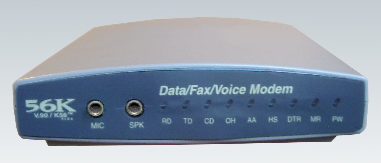
Carefully open the case of your modem and remove the PCB.
![]()
-
3Step 3
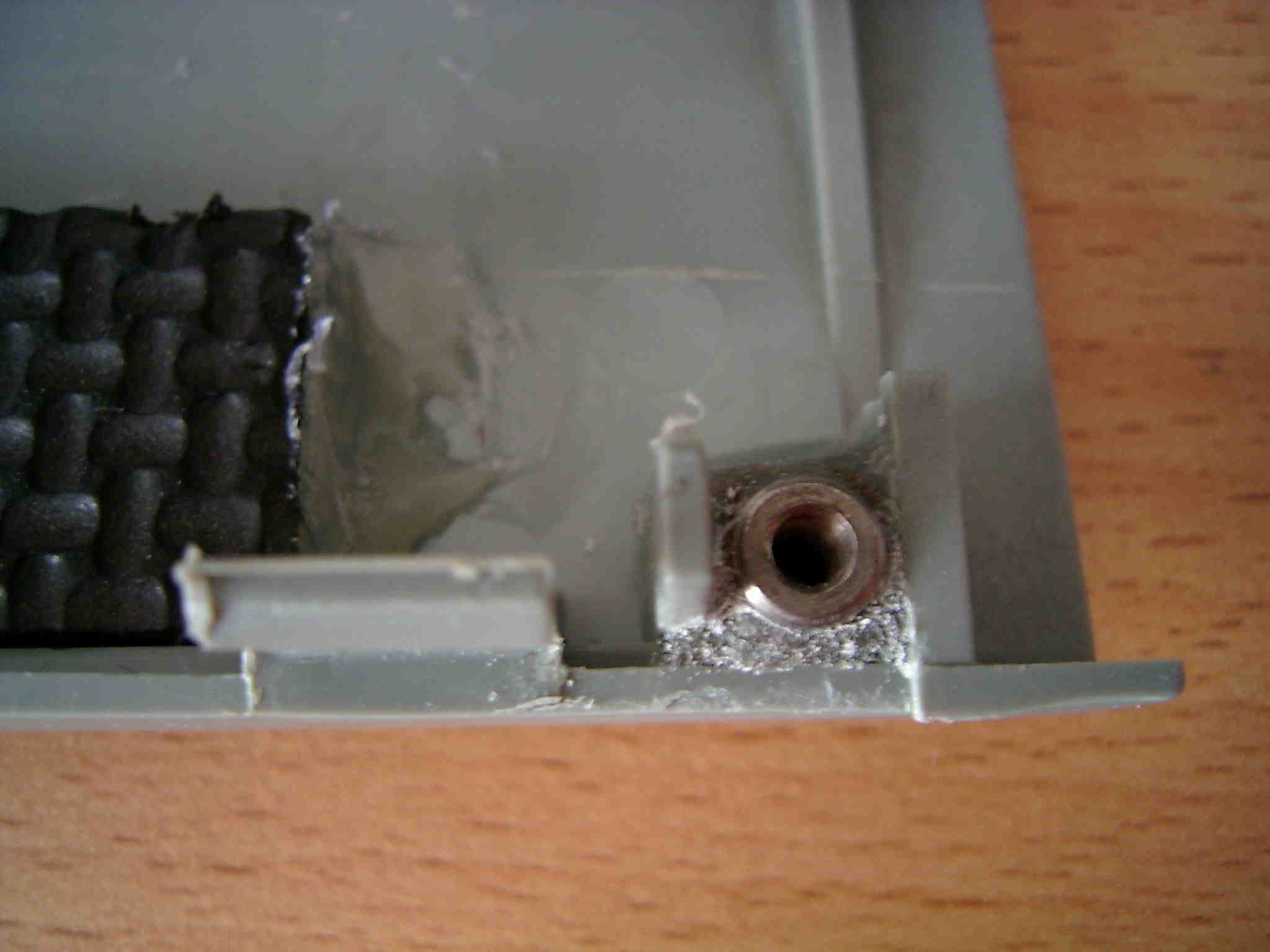
Glue four nuts into the case using epoxy glue.
![]()
Detailed view :
![]()
Note: You may have to use a milling cutter (multifunction rotary tool) to remove some plastic material from the case.
-
4Step 4
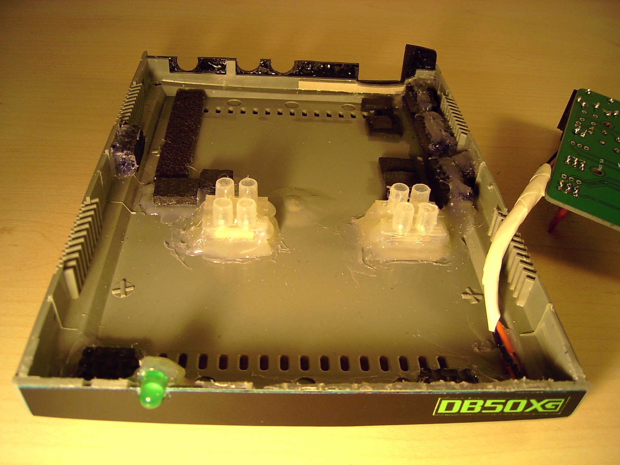
Close redundant holes with hot glue
![]()
-
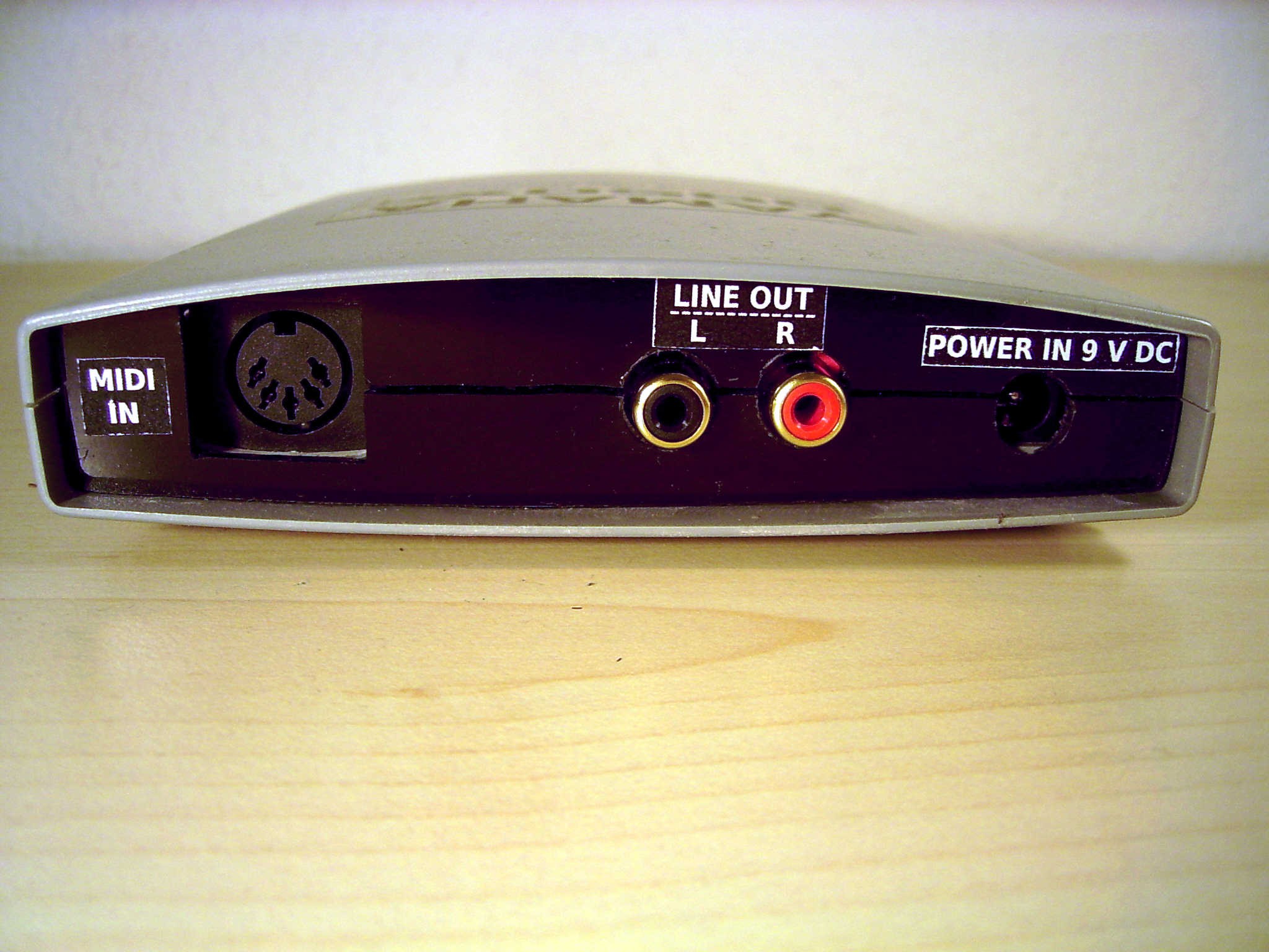
5Step 5
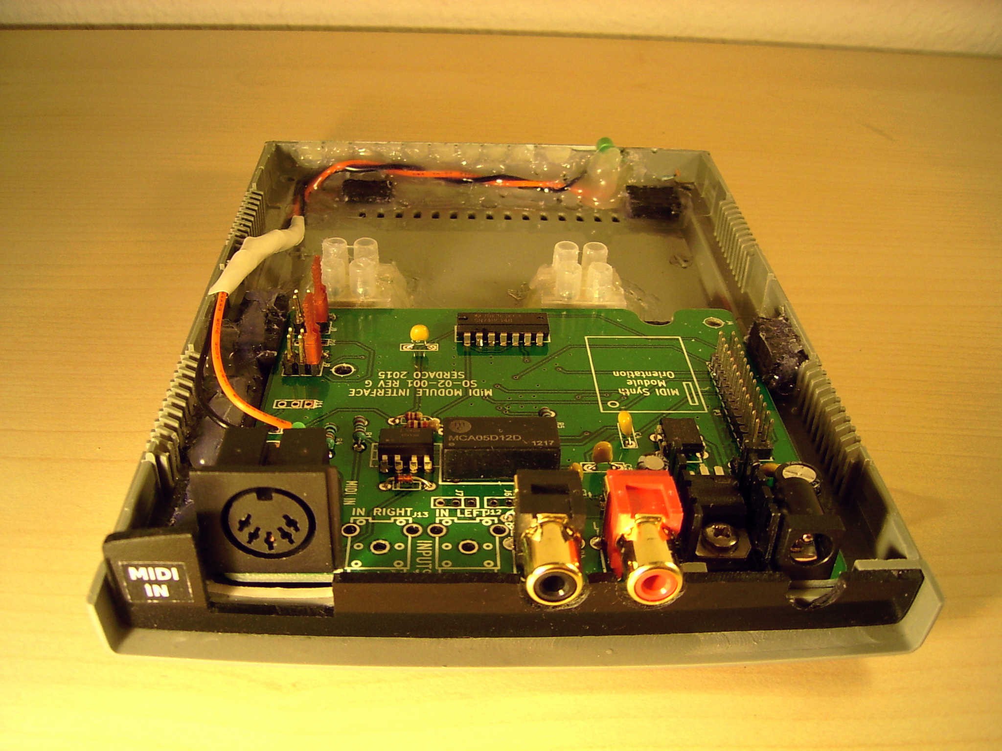
Add suitable fittings or PCB holders to the case and drill four holes in the lower part of the case. Also, create the rear panel and glue it to the case.
![]()
-
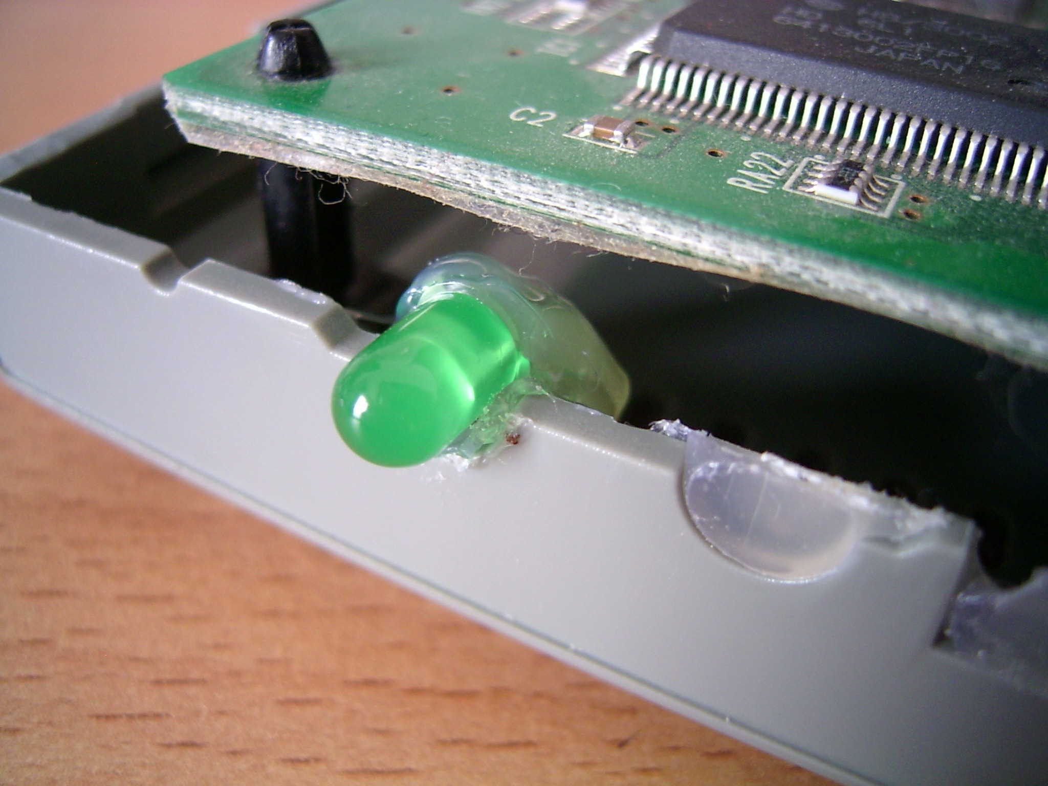
6Step 6
Build the interface board into the case, and add an LED and a series resistor. See "http://led.linear1.org/1led.wiz" for more information on how to build an LED. Use J5 on the interface board for 5 V and GND connection. See "http://serdaco.com/files/SO02001_jumpers_headers.pdf" for the pinout.
![]()
![]()
-
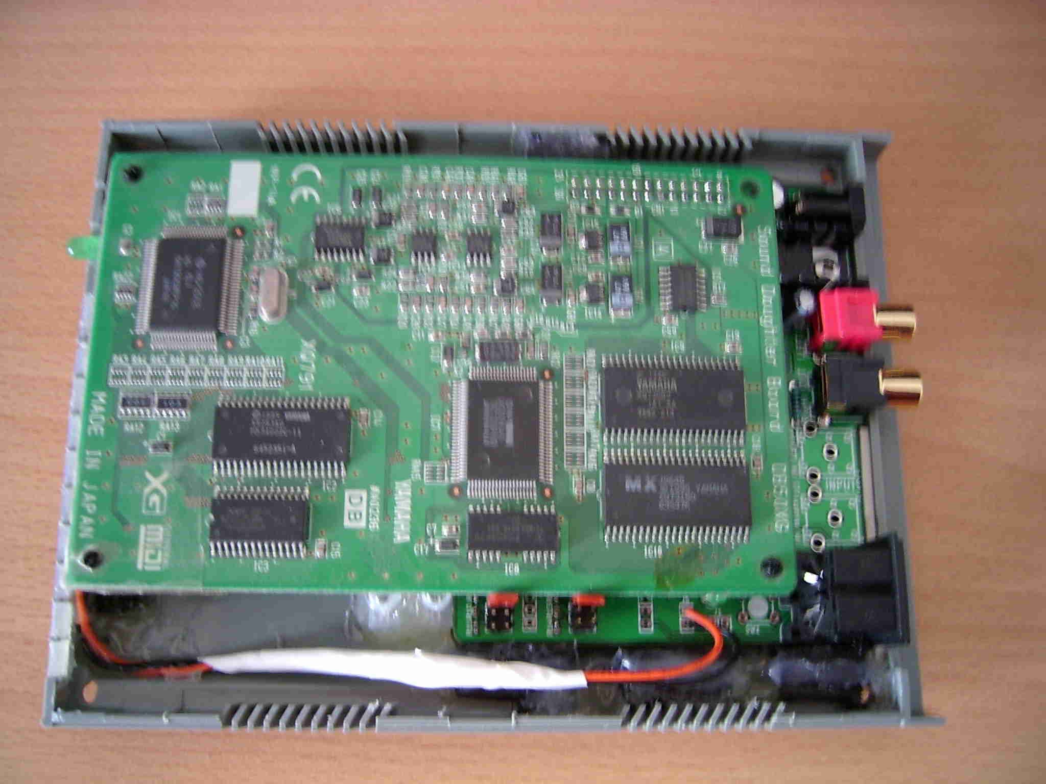
7Step 7
Plug the DB50XG onto the interface board
![]()
-
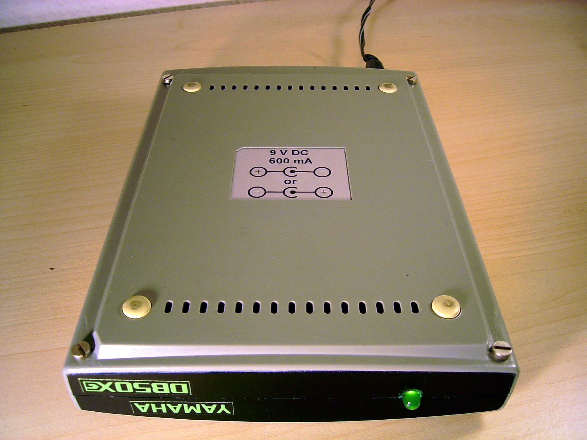
8Step 8
Close the case using four screws and add stickers to the top, bottom, front and back of the case.
![]()
![]()
![]()
![]()
-
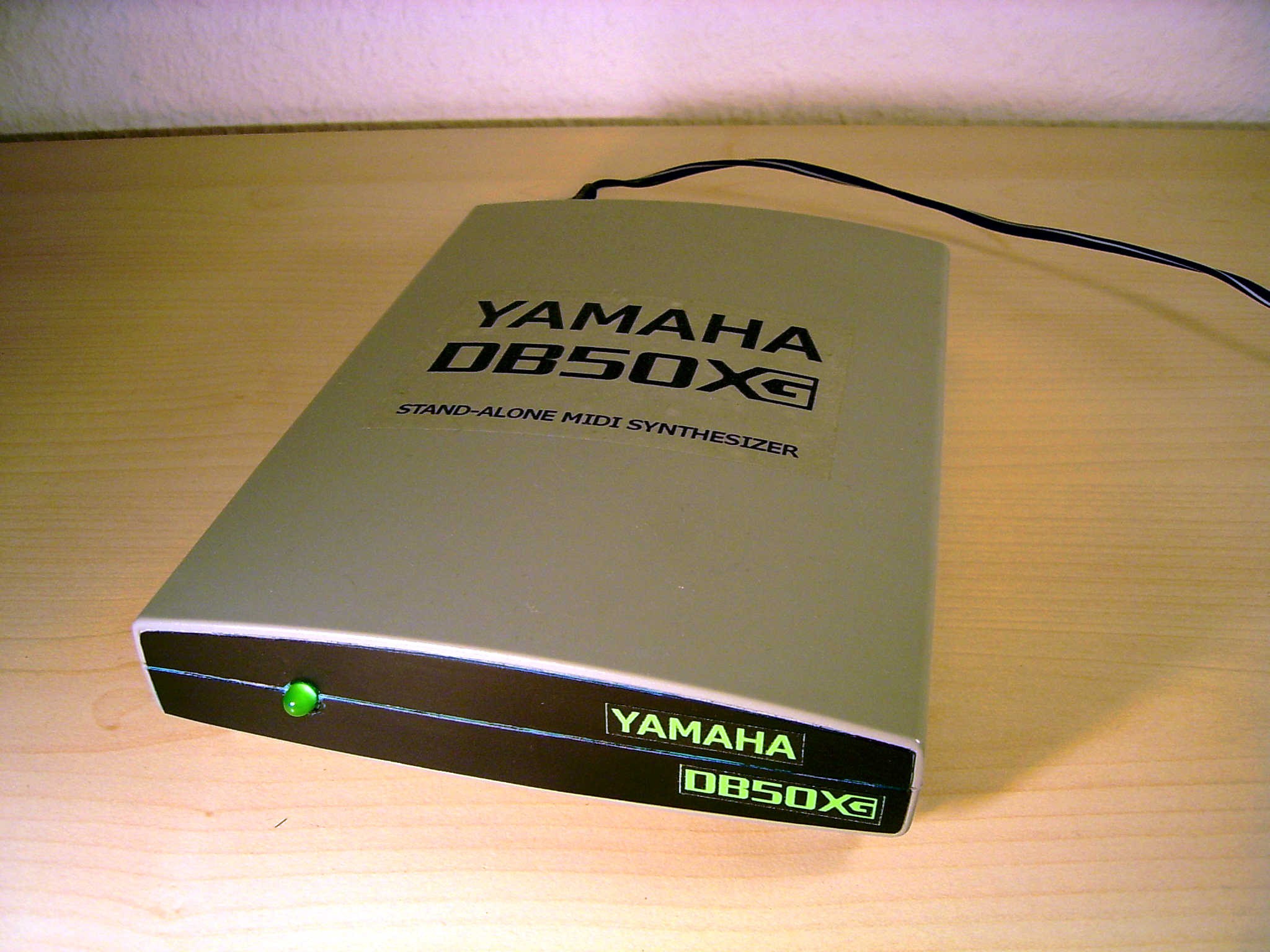
9Step 9
And here we go: A great-sounding and good-looking stand-alone MIDI synthesizer, based on a Rockwell modem case!
![]()
Turning an old modem into a MIDI synth module
My friend Christian turned his old modem into a great sounding and looking stand-alone MIDI synthesizer


Discussions
Become a Hackaday.io Member
Create an account to leave a comment. Already have an account? Log In.