Universal Battery Module
The goal is to create a bulletproof 18650 based battery solution applicable to a wide variety of tasks; solar, utility vehicles, EVs, boats.
The goal is to create a bulletproof 18650 based battery solution applicable to a wide variety of tasks; solar, utility vehicles, EVs, boats.
To make the experience fit your profile, pick a username and tell us what interests you.
We found and based on your interests.
13x20 with 18point5mm cell animation.mp4MPEG-4 Video - 21.70 MB - 03/20/2020 at 06:34 |
|
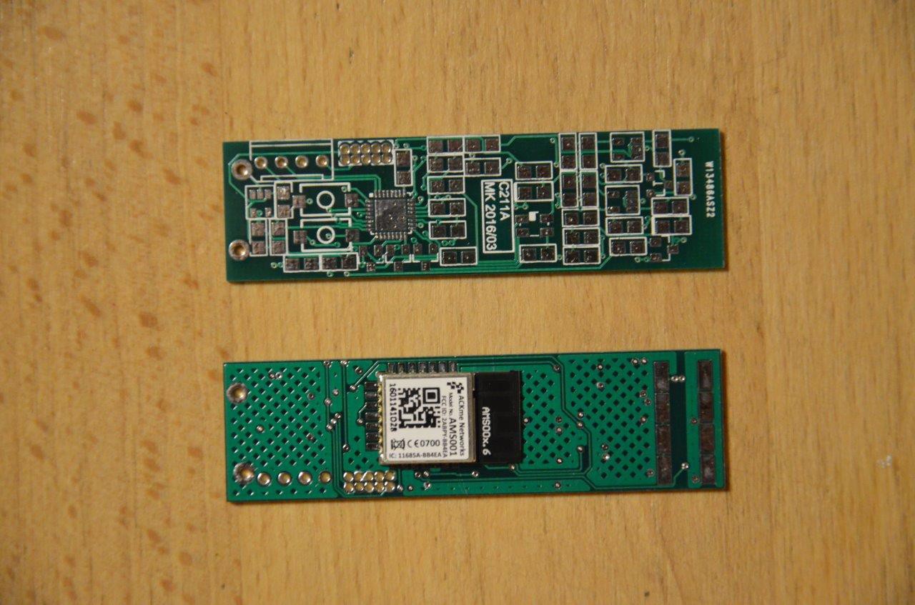
I have populated and tested the first board - Everything works fine. So far so good...
The 5 protoype PCBs from China have been delivered today - I have placed a Bluetooth module on the "bottom" side.
The quality of the PCB seems OK.
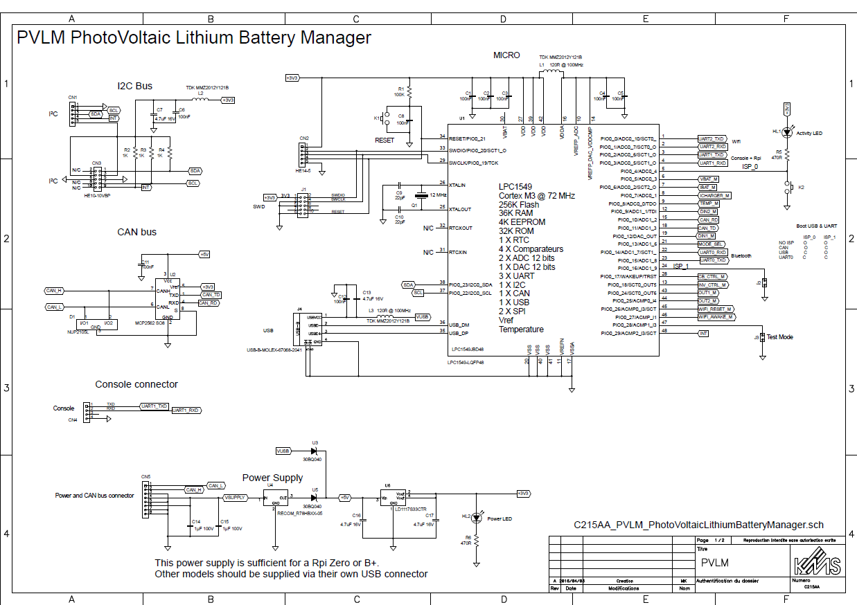
I have spent several hours on the BMS project during this week end and the schematic of the main module is finished now. The PCB patterns of all the components are also drawn :-)
The module implements an NXP LPC1549 Cortex M3 processor running at 72 MHz. This chip is really the perfect choice for this application.
I have chosen the LQFP 48 package. Nearly all the pins are used.

More about this awsome device here.
The board features:
First page - Microcontroller, Power Supply, I2C and CAN bus
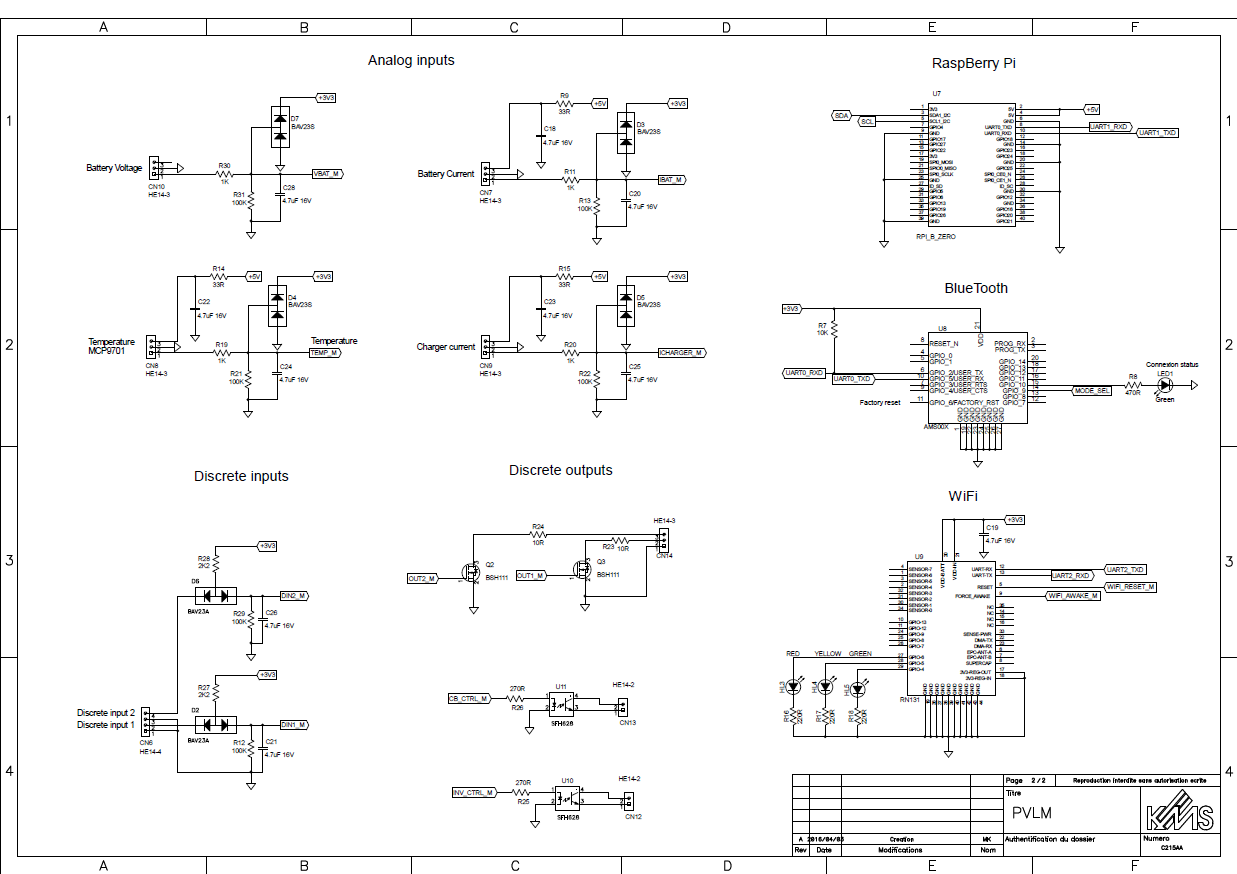
Second page - I/Os, RaspBerry Pi interface and wireless communication
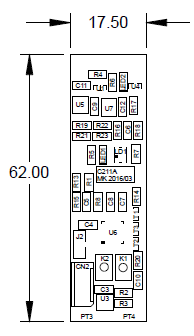
The design of the prototype PCB of the BMS Module is finished.
This snapshot shows the layout on the "top side". The board is a bit smaller than a 18652 cell.
U6 is the microcontroller
The radio module and the power resistors (for balancing) are located on the bottom side.
I have checked the board against the commonly used PCB production rules and it is OK.
I will launch the manufacturing as soon as erverthing is double checked.
This sketch shows the main components of the BMS module put on a 18650 cell outline:
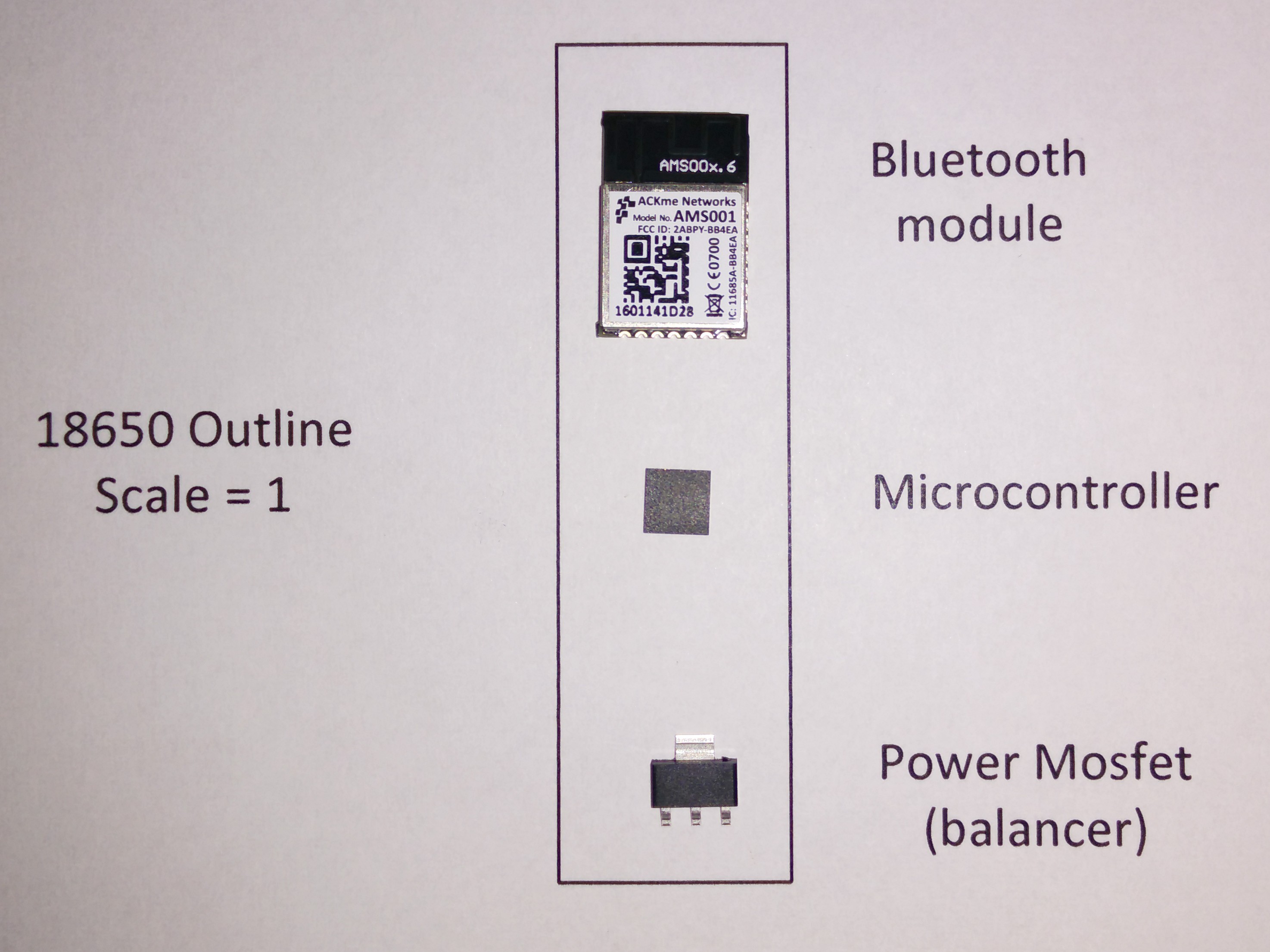
It seems possible to insert the BMS module in an empty 18650 cell. This opens new perspectives !
To be confirmed, anyhow.
The Module could look like this :
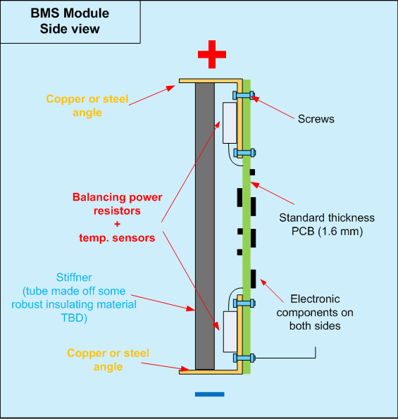
The main board is organized as follows:
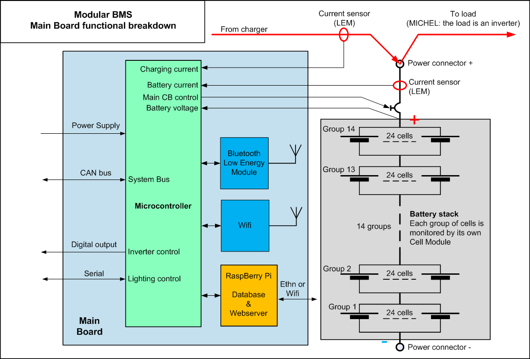
The Cell module is organized as follows:

Centralized solution
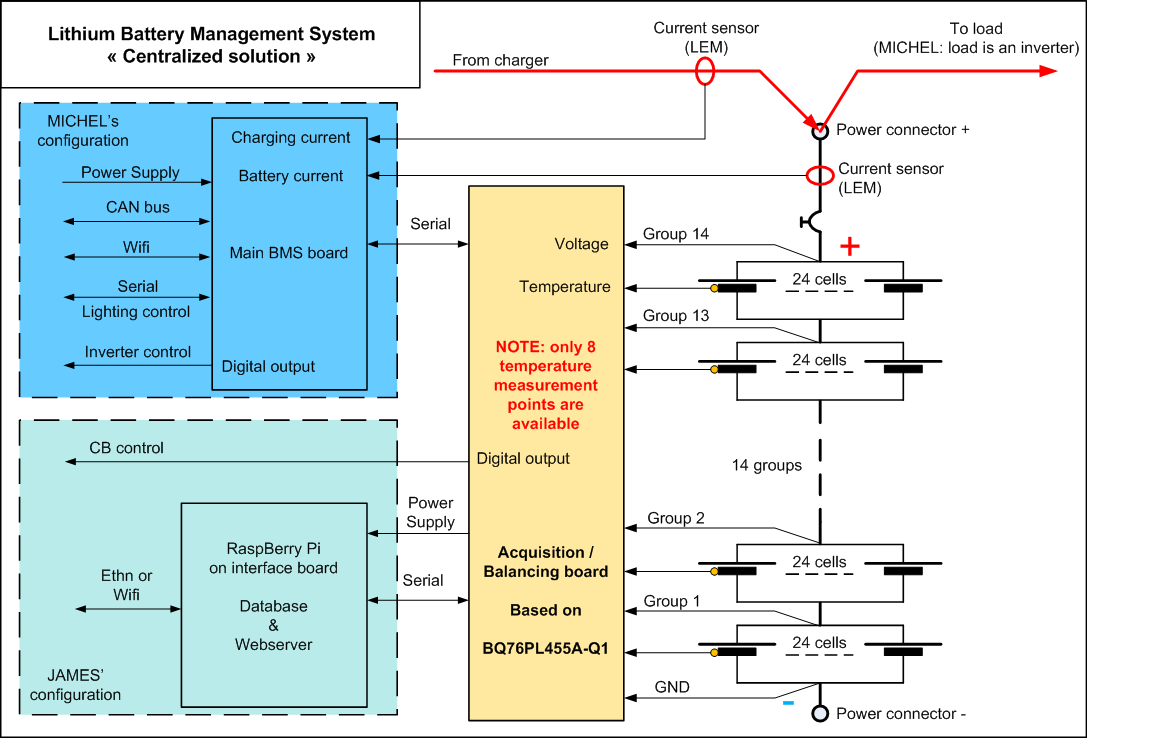
Modular solution
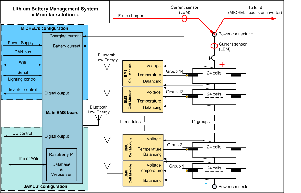
Advantages and drawbacks of each solution
| Solution | Pros | Cons |
| Centralized |
|
|
| Modular |
|
|
Regarding the Battery Management we need following functions :
At cell group level (one group = 24 cells wired in //)
At stack level ( = complete stack of 14 groups in series)
Consumption during active mode:
During active mode, the BMS monitors the battery parameters, logs them and insures battery safety.
During active mode, the consumption of the BMS shall be less than 50 Wh per day.
It shall be possible to disable / enable the BMS without having to disconnect wires. When disabled, the BMS is in storage mode.
Consumption in storage mode
During storage mode, the BMS does not perform any measurement / logging of the battery parameters.
When storage mode, the consumption of the BMS shall be less than 1 Wh per day. During storage mode a 4 KWh battery looses less than 10 % of its capacity when left sitting uncharged during one year (To Be Confirmed).
Safety
The main concern regarding Lithium batteries is overcharging. Overcharging can lead to degasing and even fire. Overcharging is avoided thanks to the passive balancing feature of the BMS. If this feature fails unexpectedly, one or more cell groups may get overcharged without CB tripping or warning. This would lead to a dangerous situation.
Following unexpected events may lead to battery overcharging / overheating
In order to mitigate these risks, the design shall include redundancy and/or built-in test mechanisms.
Electrical Protections
The cell voltage measuring inputs shall withstand 60 VDC during 1 minute without degradation
The cell temperature measuring inputs shall withstand 60 VDC during 1 minute without degradation
The current measuring inputs shall withstand 60 VDC during 1 minute without degradation
The BMS main board power supply input shall withstand 60 VDC during 1 minute without degradation
Environmental
The BMS shall be fully functionnal between 0 °C and 70 °C (32°F / 160 °F)
The BMS shall be designed to function 24 hours/day - 365 days/year.
Design rules
The BMS is intended to be used by JAMES and MICHEL in their personal applications. The BMS will be used and maintained by them during several years. Following design rules apply:
NOTE: the requirements specific to Jame's application and Michel's application of this project are tagged (JAMES) / (MICHEL) respectively.
Create an account to leave a comment. Already have an account? Log In.
Hello,
Thanks for accepting me in your project.
It would be fine you provide details regarding the internals of your solution, so I will see where I can give a hand !
I am currently designing a mockup consisting of one string of 6 cells in series. I want to evaluate the charging /discharging behavior of each individual cell. This mockup will be controlled thanks to a Beagle Bone Black hosting a database and a small webserver.
Question: what's your name ?
Have a nice day - Michel
I'm planning 336 cells per module, 3500mah each. Arranged 24 per group, 14 in series. This arrangement closely approximates the voltage of a 48v lead acid system and is compatible with inverters, charge controllers, and motor speed controllers. I'm thinking a BQ76PL455A-Q1 chip from Ti, http://www.ti.com/product/bq76pl455a-q1. Module safety and isolation using a 250 amp remote trip circuit breaker. If any cell hits HVC or LVC, trip the breaker, as well as high temperature. Connector to the the rest of the system will be an anderson SB-350, though in the future I'd like to integrate copper contacts into the base of the module that contact two parallel copper busbars when inserted into a rack. Case made of polycarbonate, total dimensions 16" x 16" x 3"
It would be useful to incorporate a wireless protocol, perhaps bluetooth for cell status and diagnostics, as well as viewing module historical usage. Ideally the system could connect to multiple modules simultaneously. Idle power usage is a big concern too, I'd like a module to be able to sit unpowered for as much as 12 months without excessive self-discharge.
My name is James.
Hi Michel. Looks like you have a very nice Solar project. It's clear you've got skills in data acquisition and display, that's something that my projects often lack. And I like your clear and concise schematics and system block diagrams. I'd love any help you're willing to provide. I've accepted your request to join the project. It also seems to me that your solar system is exactly the type of system I have in mind for the battery modules. I look forward to working together
Hello,
Your project is very interesting. I have built an off grid solar system with lead/acid batteries and I want to replace them with Li Ion 18650 batteries as soon as possible.
My project is described here: https://hackaday.io/project/2333-my-off-grid-solar-system-monitoring
I plan to use > 1000 cells to build a 10 KWh 48V stack.
I am currently building a mock up to test the concept.
I would like to join your project.
Thank you
Regards - Michel
Become a member to follow this project and never miss any updates
I have two projects, one is my job and the other is a hobby.
Job: 11 module 48V LiFePO4 batteries 70KWh/
Hobby: hack an old LG 14 module Li Ion rack to use as solar storage in a 30kW solar + storage system. I have no controller for this system so I am trying to replace the OEM canbus BMS with DIY or OTS BMS.
My name is John