Ampeater
-
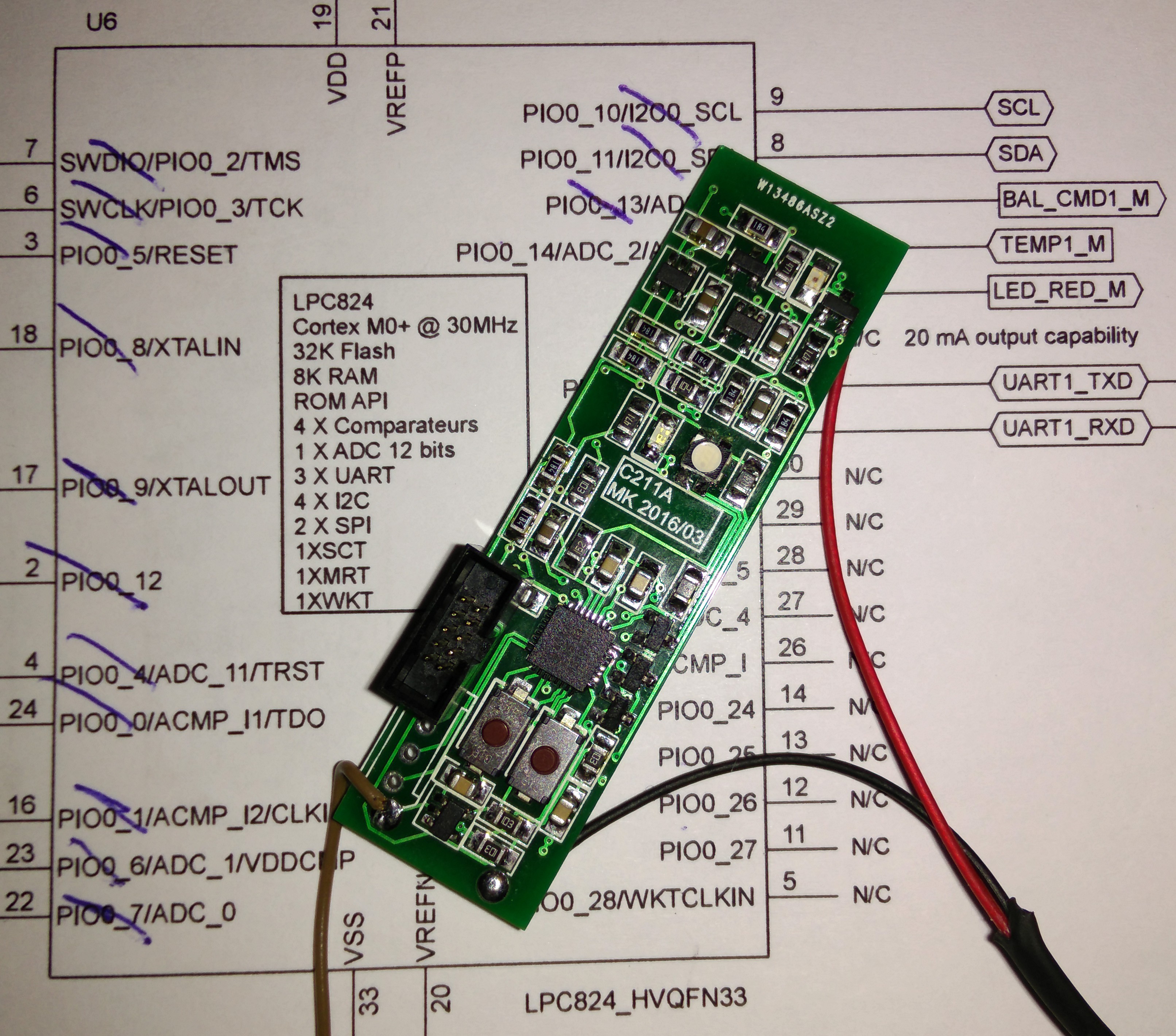
BMS Cell Module: first prototype tested
04/10/2016 at 21:10 • 0 commentsI have populated and tested the first board - Everything works fine. So far so good...
![]()
-
BMS Cell Module are delivered
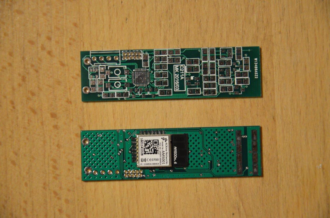
04/05/2016 at 21:19 • 0 commentsThe 5 protoype PCBs from China have been delivered today - I have placed a Bluetooth module on the "bottom" side.
The quality of the PCB seems OK.
![]()
-
BMS Main module: schematic captured
04/03/2016 at 17:43 • 0 commentsI have spent several hours on the BMS project during this week end and the schematic of the main module is finished now. The PCB patterns of all the components are also drawn :-)
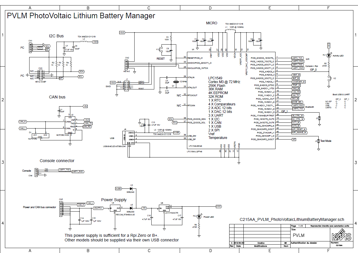
The module implements an NXP LPC1549 Cortex M3 processor running at 72 MHz. This chip is really the perfect choice for this application.
I have chosen the LQFP 48 package. Nearly all the pins are used.
![]()
More about this awsome device here.
The board features:
- Wifi
- BT Low Energy
- USB full speed
- CAN bus
- I2C
- An embedded RaspBerry Pi (A model B or a Rpi Zero can be supplied by the board itself)
- A console connector
- 4 analog inputs with 12 bits of resolution
- 2 discrete inputs
- 4 discrete outputs
- The microcontroller can boot (= be flashed) from BlueTooth, CAN or USB.
- Power supply: ultra wide 9 to 72 VDC input range (X8)
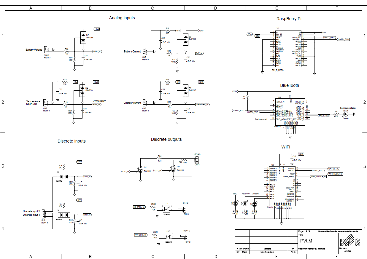
Schematic of the BMS main module
First page - Microcontroller, Power Supply, I2C and CAN bus
![]()
Second page - I/Os, RaspBerry Pi interface and wireless communication
![]()
-
BMS Module: PCB of first prototype designed
03/30/2016 at 14:43 • 0 commentsThe design of the prototype PCB of the BMS Module is finished.
This snapshot shows the layout on the "top side". The board is a bit smaller than a 18652 cell.
U6 is the microcontroller
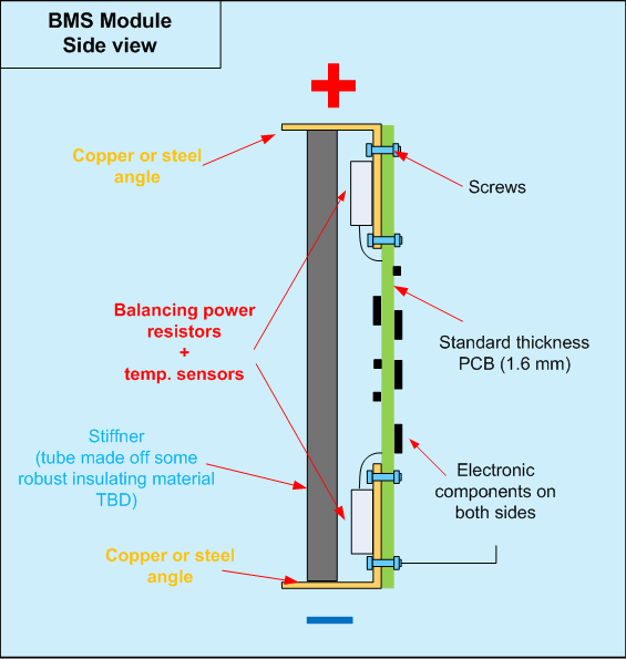
The radio module and the power resistors (for balancing) are located on the bottom side.
![]()
I have checked the board against the commonly used PCB production rules and it is OK.
I will launch the manufacturing as soon as erverthing is double checked.
-
BMS Module: can it be put in an empty 18650 cell ?
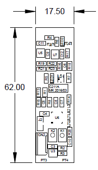
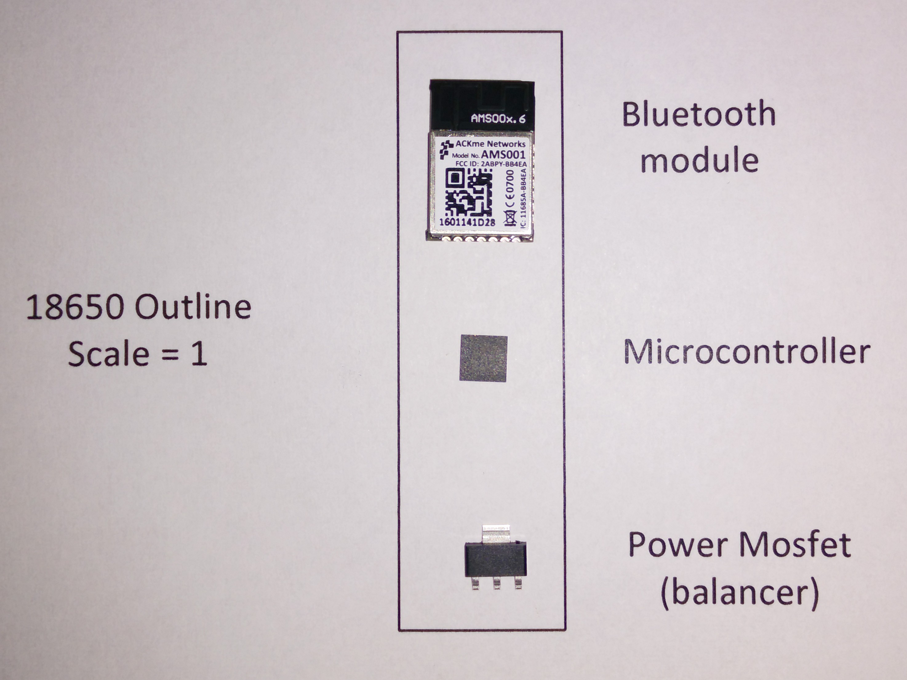
03/23/2016 at 18:37 • 0 commentsThis sketch shows the main components of the BMS module put on a 18650 cell outline:
![]()
It seems possible to insert the BMS module in an empty 18650 cell. This opens new perspectives !
To be confirmed, anyhow.
The Module could look like this :
![]()
-
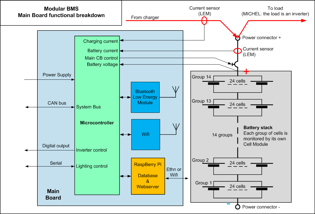
Modular BMS: Main Board functional breakdown
03/22/2016 at 20:35 • 0 commentsThe main board is organized as follows:
![]()
-
Cell Module functional breakdown
03/22/2016 at 20:24 • 0 commentsThe Cell module is organized as follows:
![]()
-
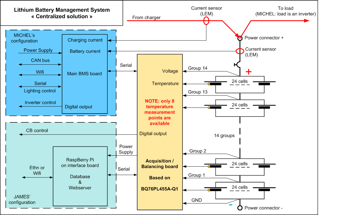
BMS design: centralized architecture vs modular architecture
03/19/2016 at 16:35 • 0 commentsCentralized solution
![]()
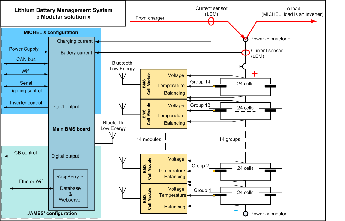
Modular solution
![]()
Advantages and drawbacks of each solution
Solution Pros Cons Centralized - Less expensive than the modular solution
- The temperature of 8 cell groups cannot be acquired.
- Lots of wires.
- 3 different boards to design.
- The consumption of the acquistion/balancing board is not easy to predict.
- In James' configuration, the acquisition/balancing board cannot work without the Rpi. Can be a safety issue in case of Rpi crash.
- Complicated Rpi monitoring/balancing programm in James's configuration.
Modular - Wires are reduced to the maximum.
- Works autonomously.
- Perfect galvanic isolation.
- Easier test, troubleshooting and maintenance.
- Easily scalable solution
- BMS own consumption is easy to manage
- More hardware.
- A little more programming effort on the microcontroller side.
- Costs more than the centralized solution.
-
BMS design: requirements and features
03/19/2016 at 07:23 • 2 commentsRegarding the Battery Management we need following functions :
At cell group level (one group = 24 cells wired in //)
- Voltage monitoring with UV and OV detection - 6 Volts full scale - 2 mV resolution
- Temperature monitoring UT and OT detection - -40°C / + 85°C (-49 °F / +185°F) scale - 0.1 °C (0.2 °F) resolution.
- Passive balancing - Power: To Be Defined
At stack level ( = complete stack of 14 groups in series)
- Bidirectional current measuring of battery current with SOC calculation - +/- 200 A - 100 mA resolution
- Unidirectional current measuring of charging current (MICHEL) - + 100 A - 50 mA resolution
- Voltage measuring - 80 Volt FS - 20 mV resolution
- Main CB control
- Inverter control (MICHEL)
- CAN bus Communication (MICHEL)
- Serial bus for lighting control (MICHEL)
- Long term storage of all battery parameters and important events
- Embedded webserver for user interaction
Consumption during active mode:
During active mode, the BMS monitors the battery parameters, logs them and insures battery safety.
During active mode, the consumption of the BMS shall be less than 50 Wh per day.
It shall be possible to disable / enable the BMS without having to disconnect wires. When disabled, the BMS is in storage mode.
Consumption in storage mode
During storage mode, the BMS does not perform any measurement / logging of the battery parameters.
When storage mode, the consumption of the BMS shall be less than 1 Wh per day. During storage mode a 4 KWh battery looses less than 10 % of its capacity when left sitting uncharged during one year (To Be Confirmed).
Safety
The main concern regarding Lithium batteries is overcharging. Overcharging can lead to degasing and even fire. Overcharging is avoided thanks to the passive balancing feature of the BMS. If this feature fails unexpectedly, one or more cell groups may get overcharged without CB tripping or warning. This would lead to a dangerous situation.
Following unexpected events may lead to battery overcharging / overheating
- Undetected erroneous cell group voltage measuring (voltage reading is too low).
- Undetected erroneous cell group temperature measuring (temp reading is too low).
In order to mitigate these risks, the design shall include redundancy and/or built-in test mechanisms.
Electrical Protections
The cell voltage measuring inputs shall withstand 60 VDC during 1 minute without degradation
The cell temperature measuring inputs shall withstand 60 VDC during 1 minute without degradation
The current measuring inputs shall withstand 60 VDC during 1 minute without degradation
The BMS main board power supply input shall withstand 60 VDC during 1 minute without degradation
Environmental
The BMS shall be fully functionnal between 0 °C and 70 °C (32°F / 160 °F)
The BMS shall be designed to function 24 hours/day - 365 days/year.
Design rules
The BMS is intended to be used by JAMES and MICHEL in their personal applications. The BMS will be used and maintained by them during several years. Following design rules apply:
- Use of obsolete or "hard to find" components or hardware shall be avoided
- Use of components that can be found easily in Europe and in the USA is required
- Minimise the complexity of wiring, testing and reduce mainenance effort
- Include indicators and troubleshooting means that allow global health diagnostic "at a glance"
- Software design shall be based on well known standards like C, HTML, CSS , PYTHON, LINUX
NOTE: the requirements specific to Jame's application and Michel's application of this project are tagged (JAMES) / (MICHEL) respectively.
Universal Battery Module
The goal is to create a bulletproof 18650 based battery solution applicable to a wide variety of tasks; solar, utility vehicles, EVs, boats.