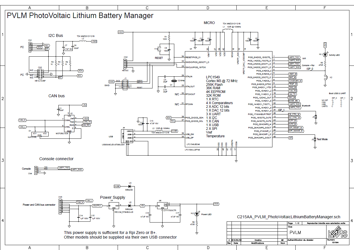
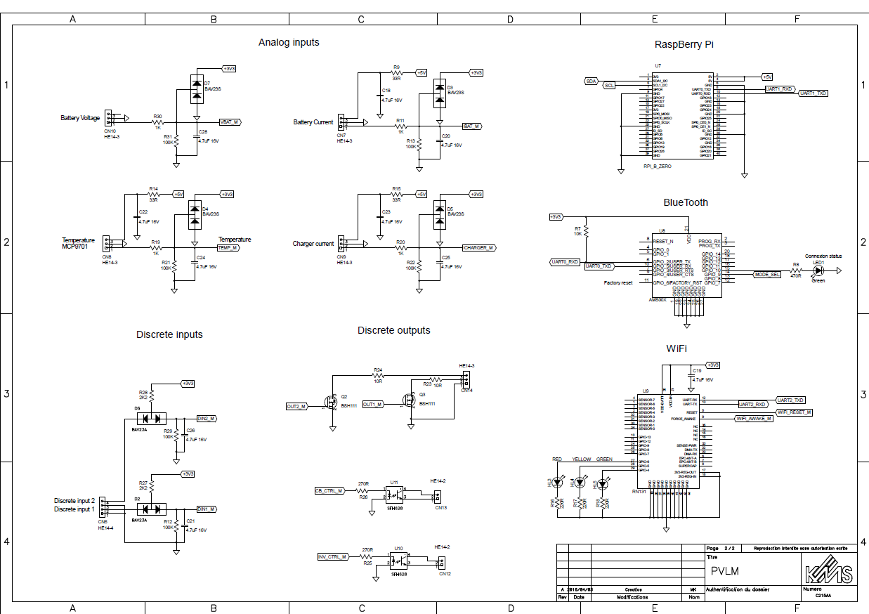
I have spent several hours on the BMS project during this week end and the schematic of the main module is finished now. The PCB patterns of all the components are also drawn :-)
The module implements an NXP LPC1549 Cortex M3 processor running at 72 MHz. This chip is really the perfect choice for this application.
I have chosen the LQFP 48 package. Nearly all the pins are used.

More about this awsome device here.
The board features:
- Wifi
- BT Low Energy
- USB full speed
- CAN bus
- I2C
- An embedded RaspBerry Pi (A model B or a Rpi Zero can be supplied by the board itself)
- A console connector
- 4 analog inputs with 12 bits of resolution
- 2 discrete inputs
- 4 discrete outputs
- The microcontroller can boot (= be flashed) from BlueTooth, CAN or USB.
- Power supply: ultra wide 9 to 72 VDC input range (X8)
Schematic of the BMS main module
First page - Microcontroller, Power Supply, I2C and CAN bus

Second page - I/Os, RaspBerry Pi interface and wireless communication

 Michel Kuenemann
Discussions
Become a Hackaday.io Member
Create an account to leave a comment. Already have an account? Log In.