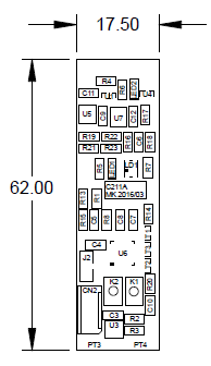
The design of the prototype PCB of the BMS Module is finished.
This snapshot shows the layout on the "top side". The board is a bit smaller than a 18652 cell.
U6 is the microcontroller
The radio module and the power resistors (for balancing) are located on the bottom side.

I have checked the board against the commonly used PCB production rules and it is OK.
I will launch the manufacturing as soon as erverthing is double checked.
 Michel Kuenemann
Discussions
Become a Hackaday.io Member
Create an account to leave a comment. Already have an account? Log In.