-
Another joystick update - 3 axis controller
04/23/2017 at 22:15 • 0 commentsThe general idea of having two 2-axis controllers is sound because this more or less resembles RC or drone controllers.
However it was clearly seen that I had huge problems with proper mounting of those KY-023 joysticks and, unfortunatelly, I had to way of attaching knobs in such way that would pass Quality Control Tests done by two experts at finding flaws: 4-year old boy and 2-year old girl.
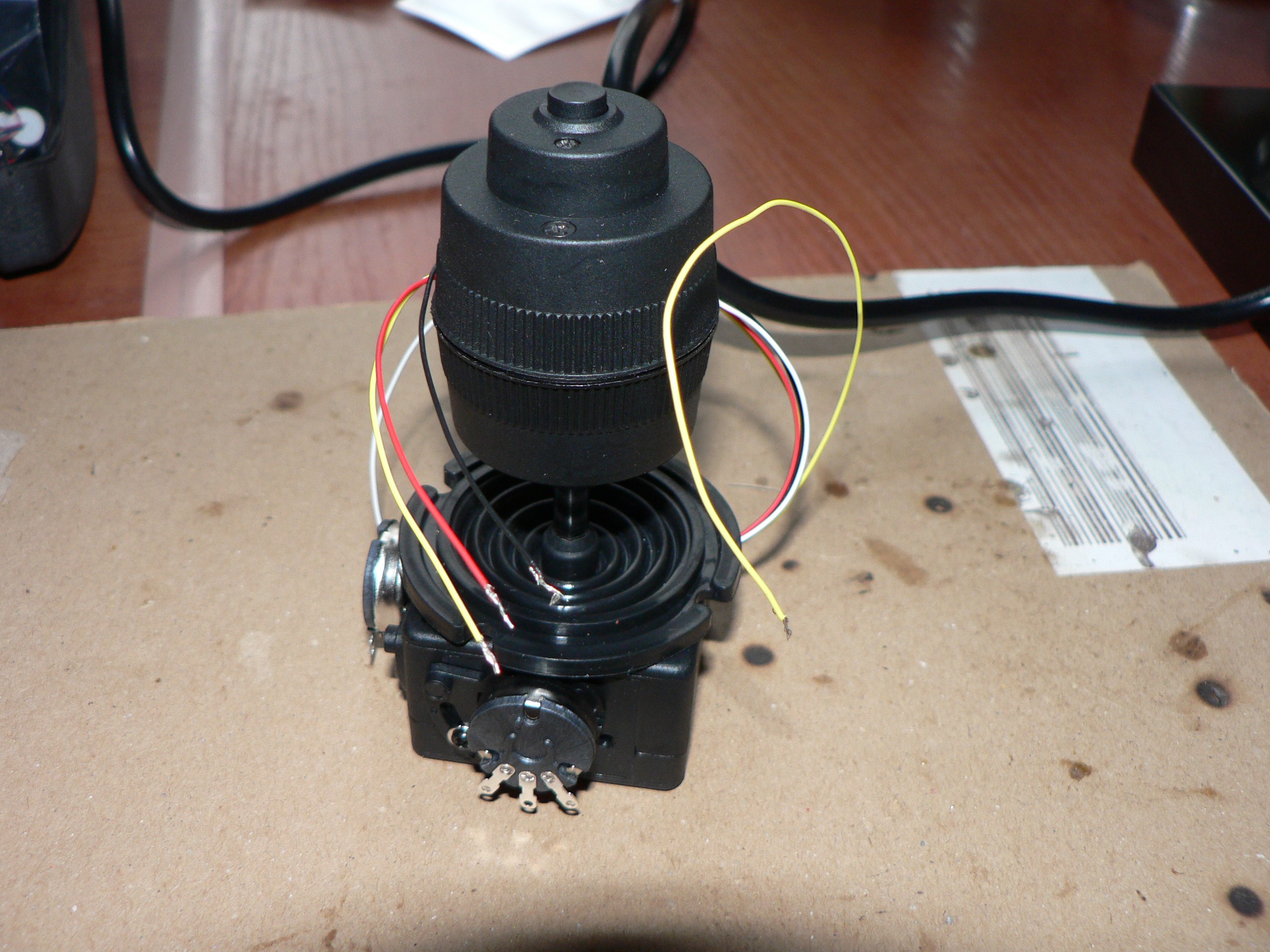
Finally I was able to find an affordable (<$20) 3-axis joystick (I don't know why it's advertised as 4-axis) like this:
Two potentiometers are exposed and I wired them in place of the left existing joystick. The handle contains third potentiometer inside that measures twist of the handle, about 45 degrees to the left or right of the center position. That potentiometer is connected to red, black and white wires. There is also and a button on the top, it short two yellow wires.
I connected this joystick to appear as X, Y and Z directions of the emulated USB joystick. I have disconnected the line to Z potentiometer from the joystick that remained the right-hand side of the board reacts only to vertical movement. I have no good use for it now and I consider removing it and replacing by something more useful. Maybe a keypad for action groups.
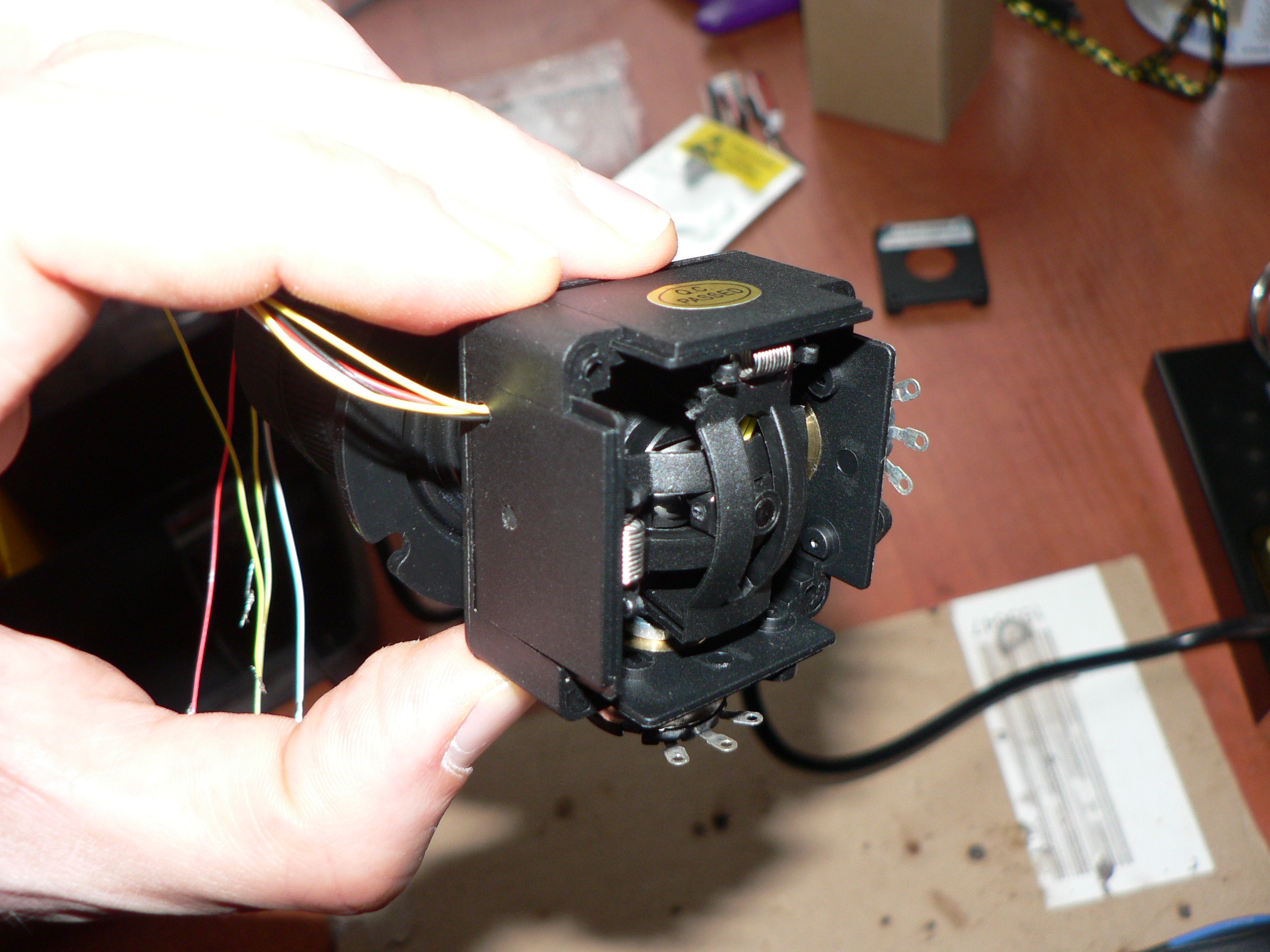
In order to mount this joystick on the board I could either drill a 35mm hole (I was not confident that I would be able to do that without damaging corners of a 35mm square with the same center - this is where mounting screws go. So instead I decided to disassemble the joystick and mount the handle from top. Disassembling just the handle is too much hassle.
Just keep notes which potentiometer was on top, which was in the bottom and which one matches the cover with hole for wires.
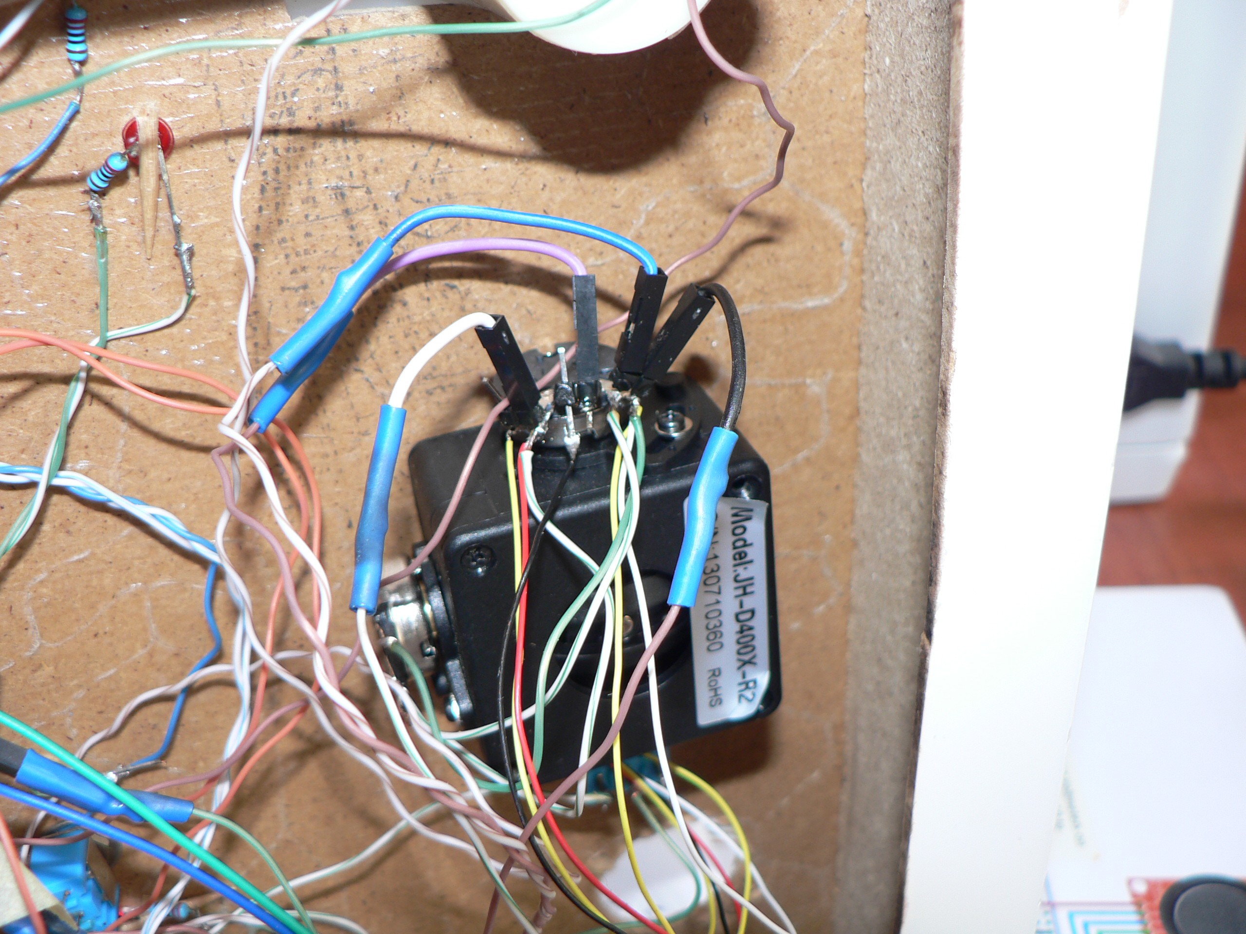
Wiring is awful and I'm ashamed to show that, but in this version it won't be better.
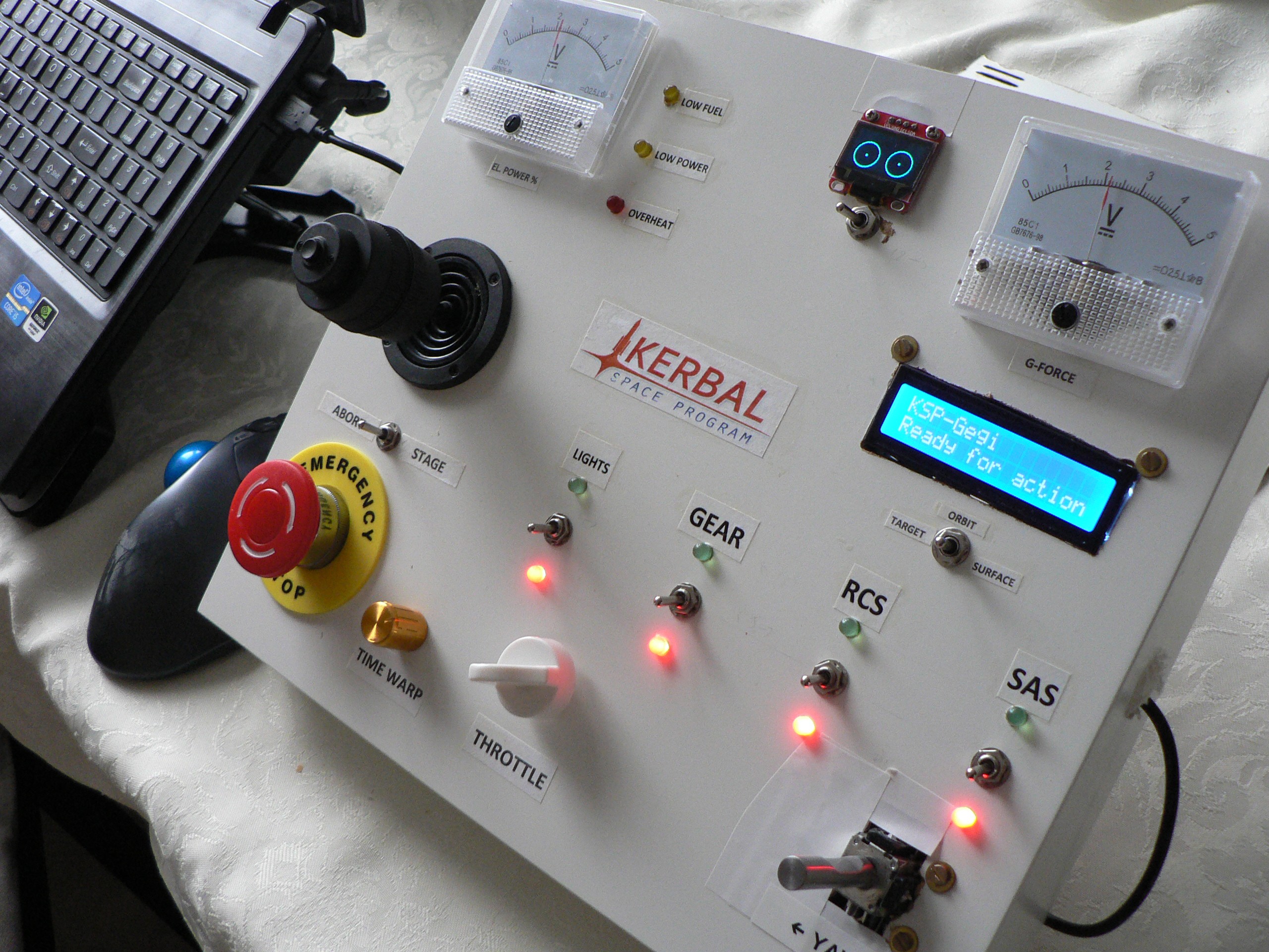
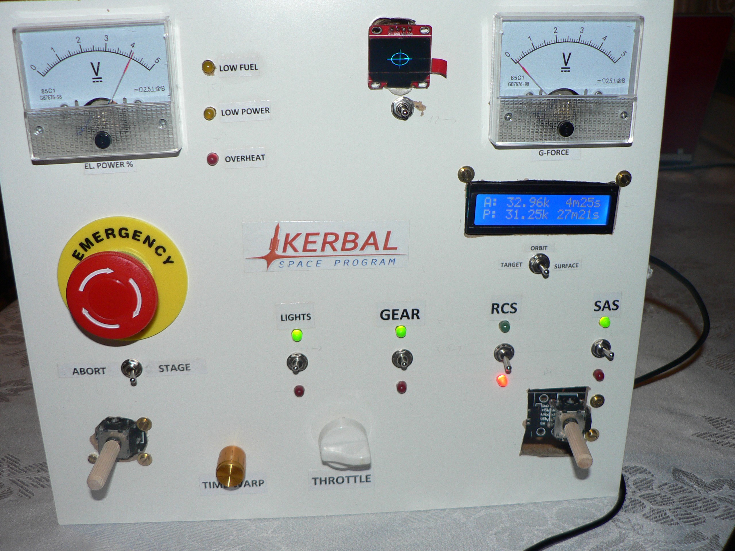
Here is the finished, updated Control Board. I the Stage/Abort push button switched places with joystick because it is more comfortable for me that way when I play.
-
Metal joystick knobs
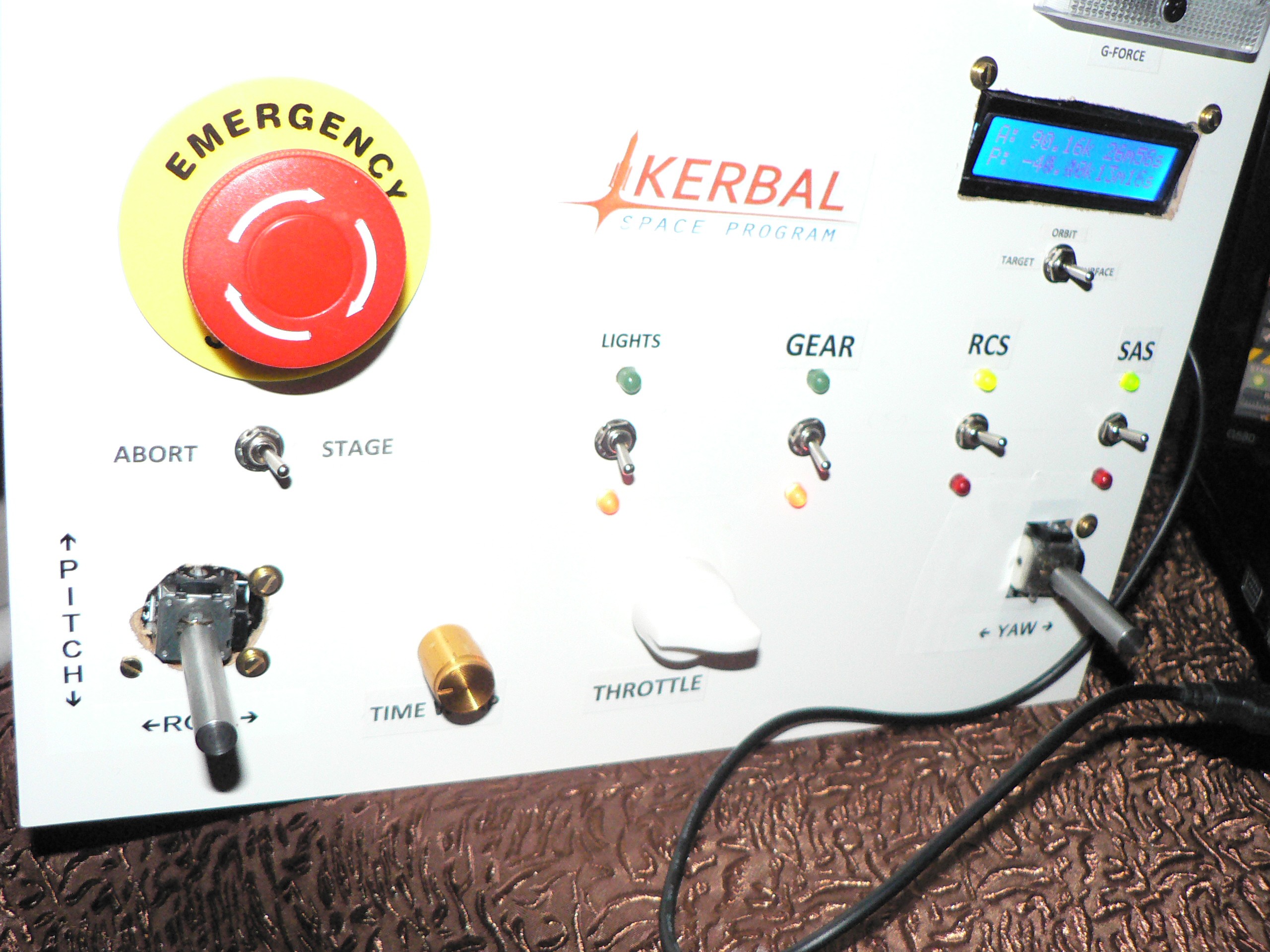
05/31/2016 at 23:03 • 0 commentsFollowing discovery of a blog about another build of a KSP console I thought it would be a good idea to try using metal knobs for joysticks. The only decent looking I found were GOTTLOSA stainless steel knobs. I got them cheaply because they are being just now removed from the store stock.
The build looks much better now. Notice new labels marking directions for pitch/roll/yaw controls.
-
KSP 1.1 and kRPC 0.3.0 upgrade
04/27/2016 at 00:05 • 0 commentsThe upgrade was easy and flawless. Great fun with starting new science career.
I have added a number of issues to the Github repository as questions to be resolved or reminders.
This is my default joystick configuration. It works great for flying rockets and EVA (but only in translation mode)
I have two open questions that I probably should ask in development thread on KSP / kRPC forum.
- What is the fastest way to find overheating part?
- What kRPC server settings are best for reducing latency?
-
kRPC upgraded to 0.2.2
04/03/2016 at 22:12 • 0 commentsIt was not mentioned here earlier, but I have used kRPC mod version 0.1.12 for development.
Finally I had some time to upgrade and test the latest kRPC 0.2.2 with KSP 1.0.5.
Unfortunately kRPC doesn't work with KSP 1.1 prerelease version yet.
-
Lessons learned
01/29/2016 at 23:23 • 0 commentsWoodwork
It's very hard to do nice woodwork without proper space, table and tools. With space, table and tools available it's just hard to do. That said, I am content with how it looks for a prototype.
IKEA LACK shelf is very easy to work with if you start with cutting through only thin boards on sides and top/bottom. They are just about 3-5mm thin. The reinforced sides (front and back, with hinges) are much thicker and tougher. To avoid them you have to leave about 1cm clearance for the front and at least 3cm on the back side of the shelf.
I made a mistake of trying to use Dremel fiberglass disc to cut through the bottom board. I thought it would be more precise. I almost started a fire of the paper honeycomb shelf insides without having access there. An oscillating tool with proper wood blade was much better choice.
Drilling in this material is very easy. Just use low speed on your drill. I made the smallest holes for screws with no effort using IKEA FIXA electric screwdriver with keyless drill jack with hex shank. Even then I had to be careful to actually drill the hole, not to punch through by just the weight of the tool.
Programming
I have tested each component separately on the breadboard so I knew what to expect: how to drive it and how to read its status.
The final software that connected these parts already worked as expected on the first run. It was coded before hardware existed in one piece.
During the course of this project I learned about latest C++11 features through Embedding C++ articles on hackaday. This was the main motivation for me to finally upgrade to latest Arduino IDE.
I was skeptical. After spending so much time on low-level 6502 assembly for C64/C128 (just check out list of my GitHub repositories) it was hard for me to believe that there is no huge cost with using C++ (instead of plain C) for AVR programming.
I restuctured my code by designing new classes to handle switches and LEDs, analog input and output (PWM). I have also replaced fixed arrays of data structures with collections of classes.
C++ classes have constructors. Instead of managing the state variables initialization myself I got it "for free" just by specyfing how constructor arguments are mapped to member variables:
digitalPin::digitalPin(const uint8_t id, const uint8_t pinSwitch) : m_id(id), m_pinSwitch(pinSwitch)So now I could remove housekeeping code. It made the program logic much clearer to see.
But the greatest thing was replacing clumsy loops over structures:
for (int i=0; i<sizeof(digitalPins)/sizeof(digitalPin[0]); i++)or equally awful:
for (int i=0; i<NUMBER_OF_DIGITAL_PINS; i++)with clean for-each iterator:for (auto &p : digitalPins) { // do something with p p.updateSwitch()Not only it is much easier on the eyes and cleaner. Not only the code is easier to maintain. I actually saved 60 bytes of flash after making these C++11 changes.Imagine my surprise. Now I don't fear, I love C++11 for AVR.
Electronics
My largest dilemma was to decide if I should drop some features and try to fit everything in Arduino Mini Pro (ATmega168) or Arduino Micro Pro (ATmega32U4) or combine them both. Or maybe I should use ATmega8 instead of Mini Pro?
Next time for the same device I would use Micro Pro again, for USB connectivity, and ATmega8 as a slave device for additional I/O pins and PWM.
Soldering the circuit was quite time-consuming because all these wires that had to be cut, stripped covered with flux, solder and finally soldered.
This circuit has only three chips and soldering the connections between them on a perforated board was very easy. The difficult part was to connect all the external components: LEDs, potentiometers, PWM output (analog voltage meters), switches and I2C bus.
My largest mistake was that I soldered and twisted all the wires that went to each component before actually mounting the components. Next time I would solder only signal wires - those that go to I/O on the board. Then I would mount the components. Only after that I would cut to the proper length and solder all the unconnected GND and VCC pins into two buses.
Oh, and I will use some kind of connectors on board. Any kind of connectors.
-
Project complete! (almost)
01/18/2016 at 00:05 • 0 commentsYesterday I have finished the last part of code that I had planned. It was a code for OLED to display orbit eccentricity and inclination. That is one mode, there are two more modes selectable by a switch, but at the moment I don't know what to show there. Some sort of targetting information? Surface landing help? It should be something graphical as rendering font seems to take too long and Arduino Micro crashes with reset. I suspect that some commands bytes are missed when it tries to render font on OLED.
I have also completed the enclosure. I have run out of time and ideas to make it better, so I just fastened the second joystick with two brass screws and I have added labels.
I must say that I'm quite happy with the console as a game controller. Two joysticks provide intuitive and precise 3-axis control and throttle potentiometer allows for fine-tuned maneuvers.
To make the console better looking I would have to start over and drill the holes again, this time patiently and correctly.
So what's left? There is still some work to do:
- organize my notes and write down the documentation here
- figure out what to do with two additional OLED modes
- write "Lessons learned" post here as a conclusion and there is a lot there: about woodwork, how to avoid a mess with wires next time, and why not to fear to use C++ features in microcontroller code
-
Test mode
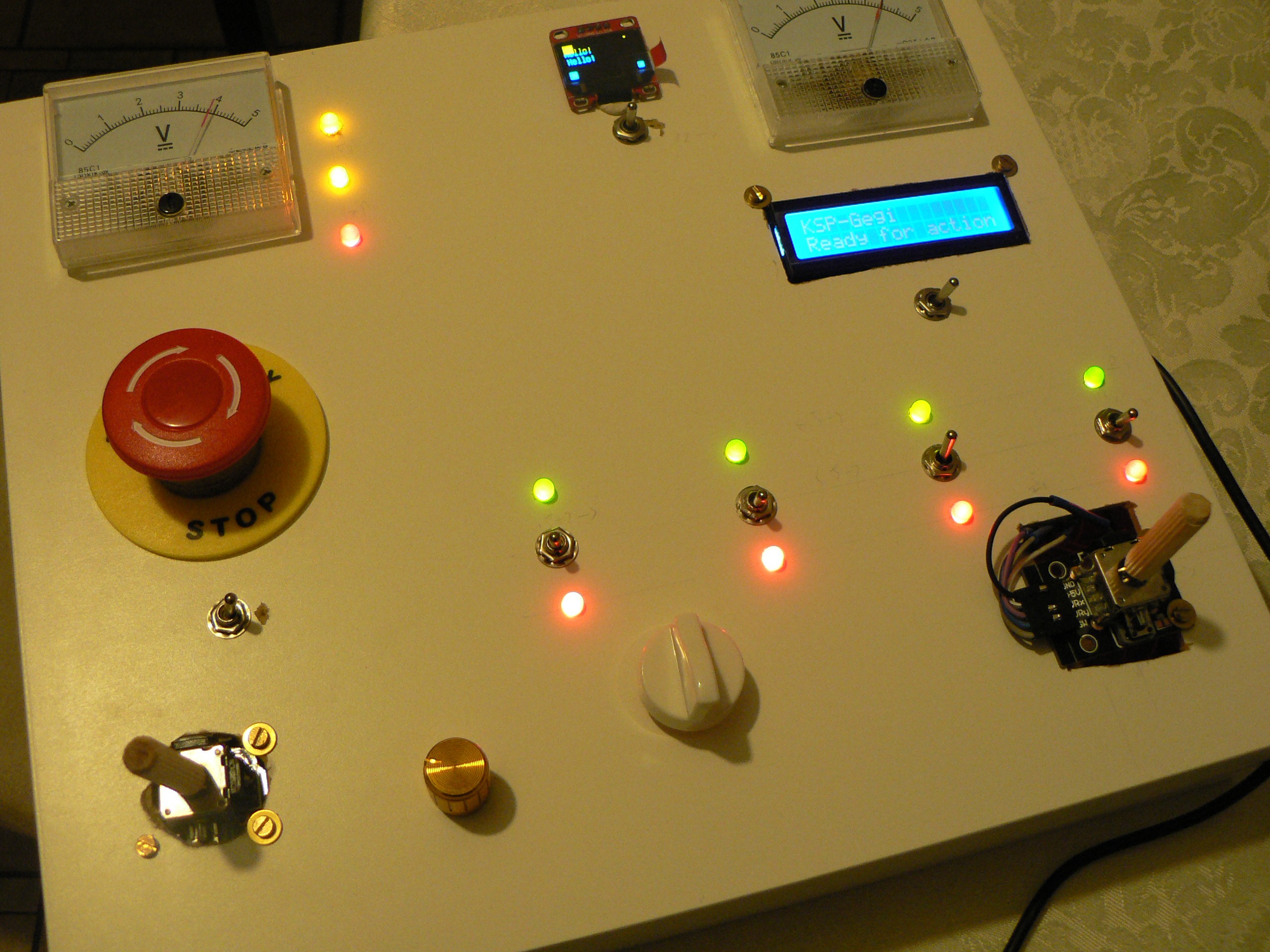
01/10/2016 at 23:29 • 0 commentsI have added test mode to the controller. Until 'R'(eset) command is received from Python kRPC script the controller will just react to the events on its own.
The four Lights/Gear/RCS/SAS switches will turn red/green LEDs on and off.
Throttle and Time Warp potentiometers will drive the two analog voltmeter displays.
-
OLED graphics commands work!
01/10/2016 at 11:59 • 0 commentsAs mentioned in one of earlier logs, I have implemented OLED drawing capability as a simple interpreter for graphics string commands sent over serial link.
There are now seven commands available:
- STOP - stop processing, string terminator
- STRING, x, y, <string terminated with '\'> - draw string at specified postion
- BOX, x, y, width, height - draw filed rectangle
- FRAME, x, y, width, height - draw rectangular frame
- PIXEL, x, y - draw single pixel
- HLINE, x, y, width - draw horizontal line
- VLINE, x, y, height - draw vertical line
- LINE, x1, y1, x2, y2 - draw line from (x1,y1) to (x2,y2)
Whole graphics string must implement whole scene. The screen is refreshed only when new graphics string is received.
Here is an example of such string:
FRAME 0 0 10 16 FRAME 10 0 10 24 FRAME 0 16 127 16 PIXEL 23 23 STRING 0 32 Line1\I had just enough memory left to have this implemented with some additional serial debug commands.
Only then I learned about font variants in u8glib and I changed:
u8g.setFont(u8g_font_unifont);
tou8g.setFont(u8g_font_unifontr);
The 'r' version has only glyphs for codes 0x20-0x7f, but that's exactly what I need.There is again enough of flash memory left to implement a test mode - to have some blinking lights without Python kRPC interface attached.
-
Final solder application
01/08/2016 at 08:16 • 0 commentsAll the LEDs are connected and installed.
It's high time for Python interface improvement.
-
OLED screen connected and tested
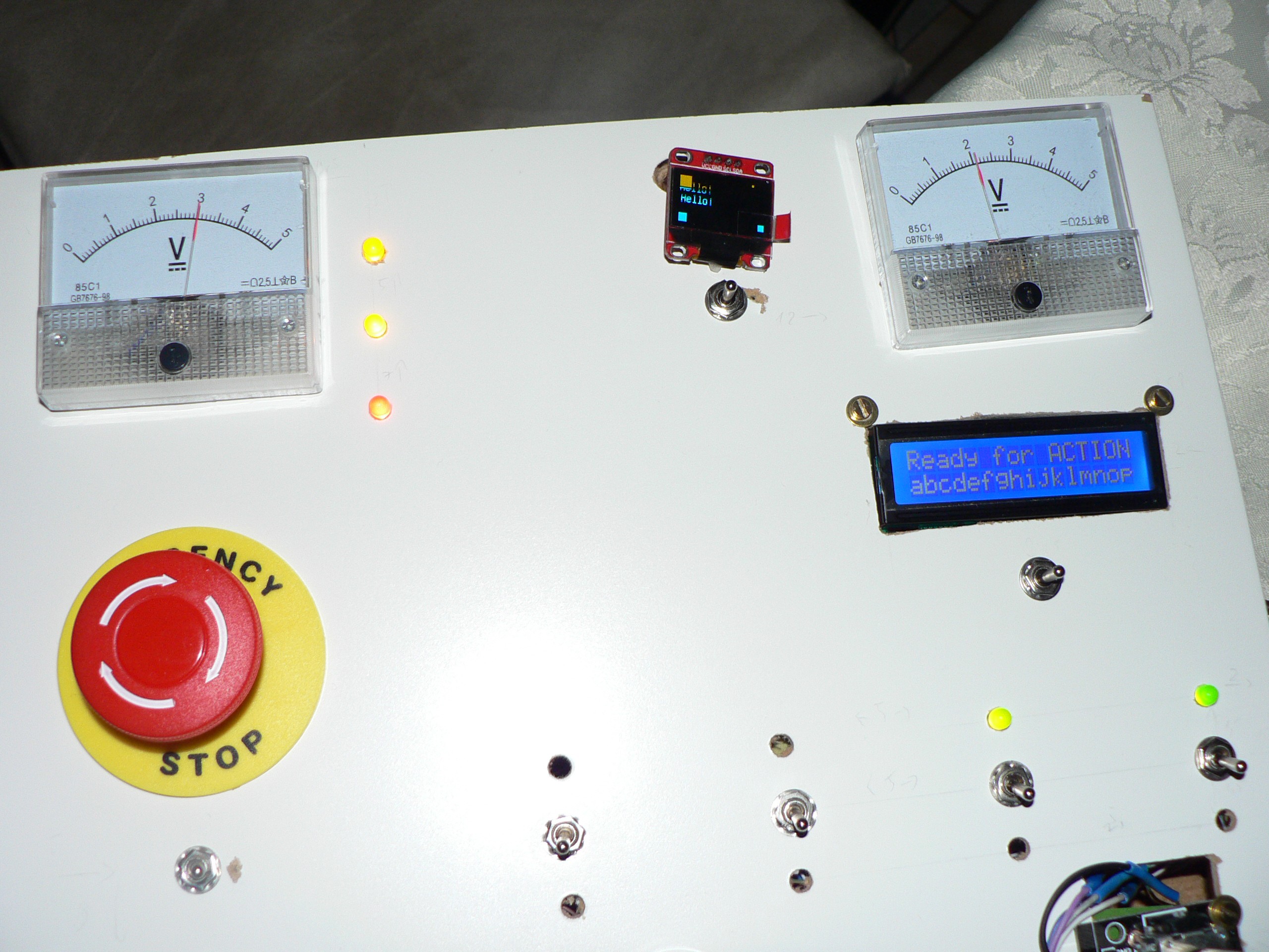
01/07/2016 at 20:21 • 0 commentsHere is how OLED screen looks like when actually displaying something
I use u8glib to control this SSD-1306 i2C 128x64 OLED display, but it's very flash-consuming. Adafruit library for this display is even worse. I have almost 3000 bytes left and I hope that it will be enough to develop some kind of graphics command string for drawing primitives. See how it was done in '80s in GEOS operating system.
This way Python interface would do the processing and prepare final drawing commands or even whole frame buffer and send over serial link. I have to keep in mind that refresh rate seems to be quite low. Besides, I have very vauge idea what should be shown there in each of three possible modes.
If 3000 bytes is not enough, I will move LCD code from Arduino Micro to Mini Pro and I will have some 6000 bytes left. Also LCD and OLED won't be on the same i2C bus anymore.
 Maciej Witkowiak