This project has fallen to the way-side...
There've been lots of related-sub-projects since the last log...
I should link those. (TODO)
One is @johnowhitaker's #Mini PCB printer, which I'm ecstatic to be a part of.
This guy uses a laser-diode from a DVD-drive to melt laser-printer toner directly onto bare copper-clad board as an etch-resist. There's a bit of fine-tuning involved, but I think with enough practice this could be quite the interesting/useful technique for many things. PCB-etching, of course. Also, maybe, creating "silk-screen" style labels for instrument-panels, and more. It's a bit of a bummer I've not put more effort into that fine-tuning, as I really think this could be useful.
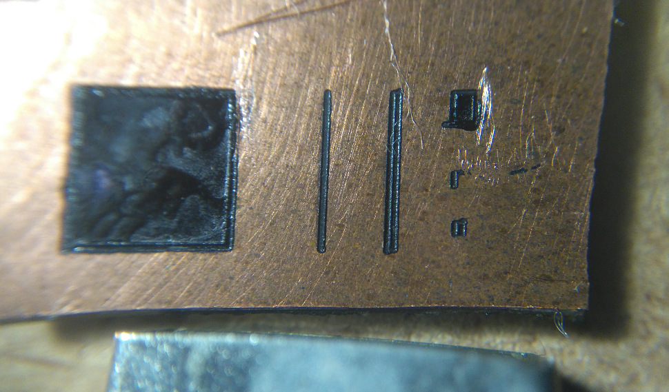
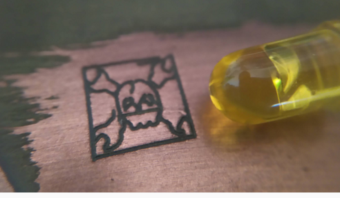 johnowhitaker is *way* better at getting actual CNC-machines up-and running than I... Here's my first "hand-drawn" experiment, which was very promising, the squiggle in the upper-left.
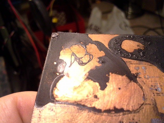
Interesting aside, just occurred to me. A little setup, first: Using this method makes a "trace" of solid plastic wherever the laser passed-over.
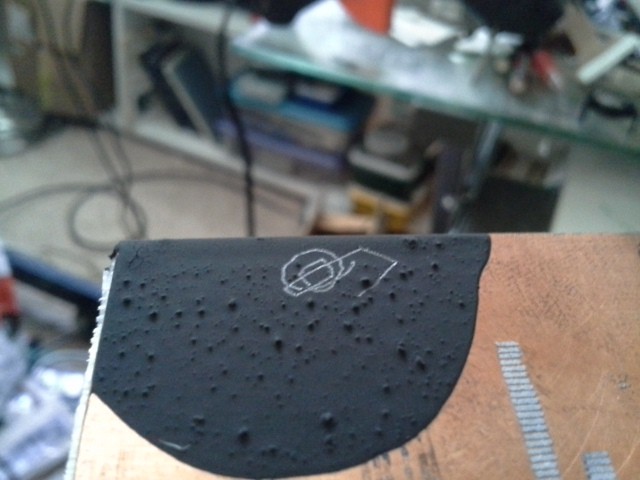
When the laser's not adjusted to the right power to heat the underlying copper, that solid plastic trace doesn't adhere to the copper, and can actually be pealed-up from the surface. This might be useful for, e.g. "isolation-routing"
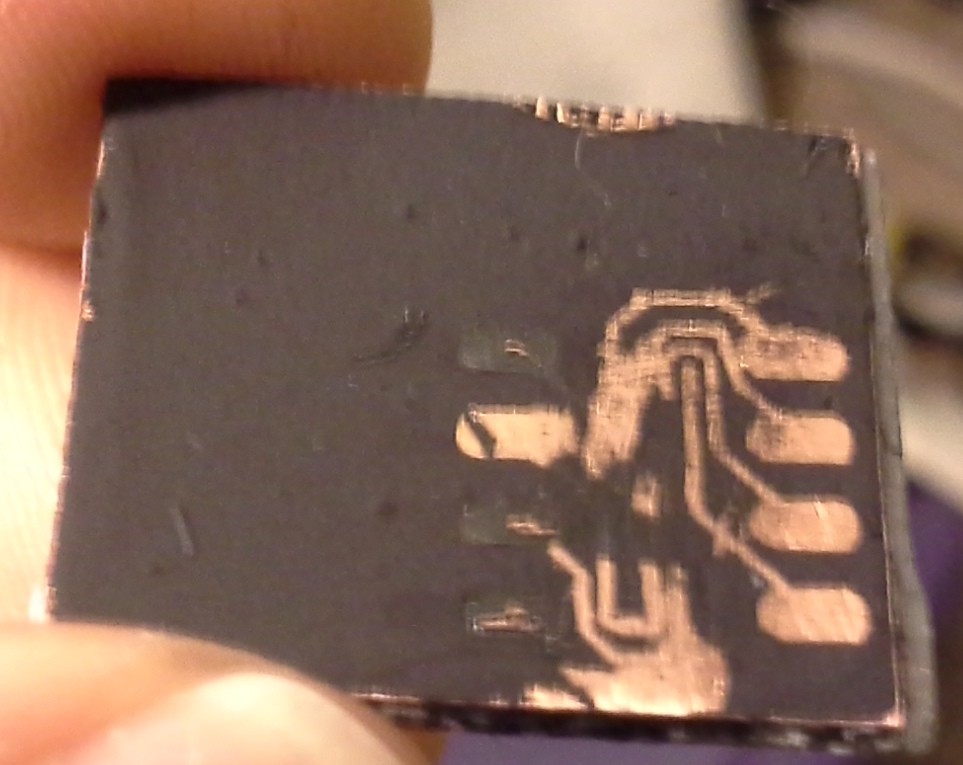 Or, which I just-now thought of, creating a stencil/silk-screen.
Again, for face-plate labels, once the solid "traces" are removed, the
labels could be spray-painted onto the surface.
Hmmmm... Similar could
be used for spray-paint solder-masks... Hmmm...
---------
As far as its direct-relation to *this* project... Well, briefly, I've ported GRBL to PIC32 and abstracted it a bit so it should be more-easily ported to other architectures. Additionally, I added the option for direct-control of steppers via directly-wired H-Bridges (rather than using Step/Dir stepper-driver boards), which should also be somewhat easily modified for e.g. driving DC-motors with optical-encoders (like used in this project). That GRBL-abstraction was a *much* larger undertaking than I expected. But now that it's been done, any further modification should be quite a bit simpler.
GRBL, of course, would be quite-handy for this project. I'd already developed HPGL-based software to do the same... it's not perfect, but definitely functional. And, usually, I have a tendency to "reinvent the wheel." But G-Code is well-supported these days, and G-Code "senders" are pretty-durn-sophisticated. So, a new path for me: abandoning my old home-brew motion-control software in favor of something much-better-established, more fully-implemented, and open-source.
Haha, here's a ridonculous image where I tried to use this project for long/skinny PCBs:
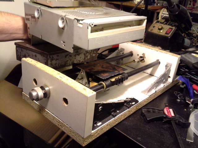 It's not a bad idea, but gravity doesn't have to be your enemy, and in fact can be your friend (In other words: turn the danged setup on its side!)
-------------
Oy, none of that was even the point of this log... The point of this log was:
I ran out of solderless-breadboards, so had to take apart one of my old projects, which *was* for this project... and I wanted to make sure I had the schematic somewhere so I could repeat it... Whelp, I didn't put that on this project's page, for some ridonculous reason... and finding it was a pain... so here it is:
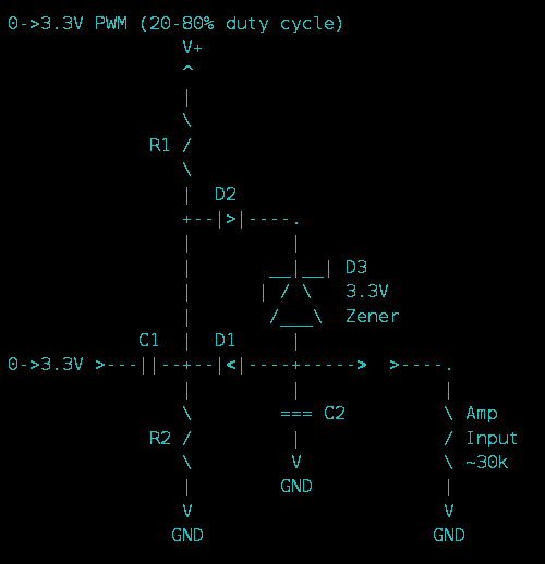
Briefly: I'd been doing experiments with using linear audio-amplifiers as motor-drivers. Not sure exactly why, but definitely a curiosity, and I'm pretty proud of that circuit... That circuit takes a PWM-input, toggling between 0V and 3.3V, and outputs an analog voltage that varies, roughly, from -1.5V to 1.5V. (Yeah, I have a single-supply linear audio-amplifier chip which requires a 0V-centered input-signal. Weird, eh?) And, I think, this circuit can be tuned such that quick/large-changes in PWM-value result in pretty-quick changes on the output-voltage, but that has yet to be thoroughly-explored.
If curious, check around the logs at that project-page #Random Ridiculosities and Experiments.
--------
And, on that note, and briefly-touched-on in the previous log on this project-page... I also worked quite a bit on #anaQuad!, which uses the *analog* output of optical-encoders (such as those found on old computers' ball-mice, or even some optical-encoder modules, and even a couple hall-effect sensors on an old brushless-DC motor like those found in CD/floppy spindles) to *greatly* increase the precision... With anaQuad, a 72-slot encoder can precisely resolve 1152 (or more!) different positions per revolution.
 It does-so by detecting *crossover* between the two analog input-channels, making it surprisingly noise-immune (for an analog signal) and adding a bit of inherent hysteresis. And, the code is pretty fast... instruction-count-wise, from entry-to-exit of detecting a change in position, it's on-par with detecting regular ol' 4x digital-quadrature.
 Eric Hertz
Discussions
Become a Hackaday.io Member
Create an account to leave a comment. Already have an account? Log In.