 Eric Hertz
If you look through my projects you'll probably see that I've got a lot of *plans* for CNC systems, but nothing actually built, yet...
There's:
- #CD/DVD mechanisms and cartesian thinggie[s?]
- #2.5-3D thing
- ... huh, I thought there were more...
- Well, there's the hanging pen-plotter system I made years ago from legos...
- Oh yeah, there's the groovy microscope-slide mechanism I meant to automate...
- There's also several systems I've written software for, but were *built* by/for others.
It's time for me to build my own CNC system, dagnabbit!
A couple months back I got completely fixated on it and assembled the first axis from stuff sitting in my stockpiles.
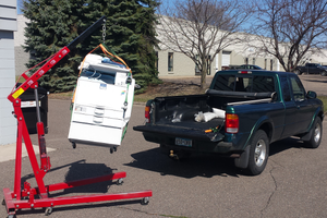
The first necessity: a "drill-press." Those rails are 1/2in in diameter, so I needed to drill 1/2in holes in the particleboard end-plates. Doing it with a hand-held drill would be difficult. Drilling both plates at the same time would assure the holes' alignment, so the rails would be parallel, but drilling perfectly vertically would require a jig, what better jig than a drill-press? Additionally, my hand-held drills don't have chucks large enough for a 1/2in drill bit, so...
#rotary-tool-drill-press to Drill-Press conversion
Back to the first axis of this "Big Ol' CNC":
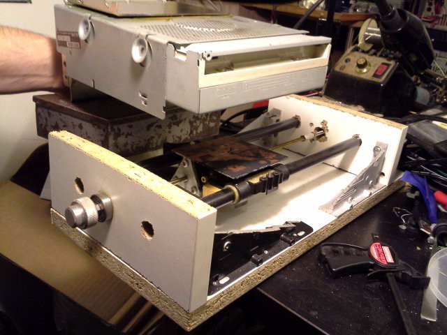
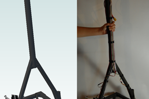
The "carriage" is from an old dot-matrix printer. It came with its own leadscrew, but it was something like 1in per turn, much too high for my intentions. It also came with rails, but I have no idea where they wound-up. The black rails are nothing more than pipe... not sure where they came from. They are a little bit tight and you can feel differing amounts of drag at different positions, but it seems OK, for a first-go.
The leadscrew is just a piece of threaded-rod I had laying around that was about the right length. I think it's 10-32. It's a little short, so I found a metal stand-off that was long enough but 6/32, so drilled it out and rethreaded it. Then I butted the threaded-rod against a long bolt of the same threading.
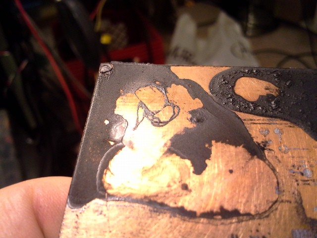
Below is the home-made tap, from a bolt, a little filing while spinning in a drill, and a cut-off-wheel.
(TODO: Better notes on making a tap! Or just link to the part in the drill-press conversion project).
The bearings at either end (not visible in the first picture) are much too large inner-diameter for the threaded-rod, but I just happened to luck-out that some of the nuts in my possession had rounded edges, so when tightened against the bearing cause the rod to center darn-near perfectly. Two nuts on either side lock them in place.
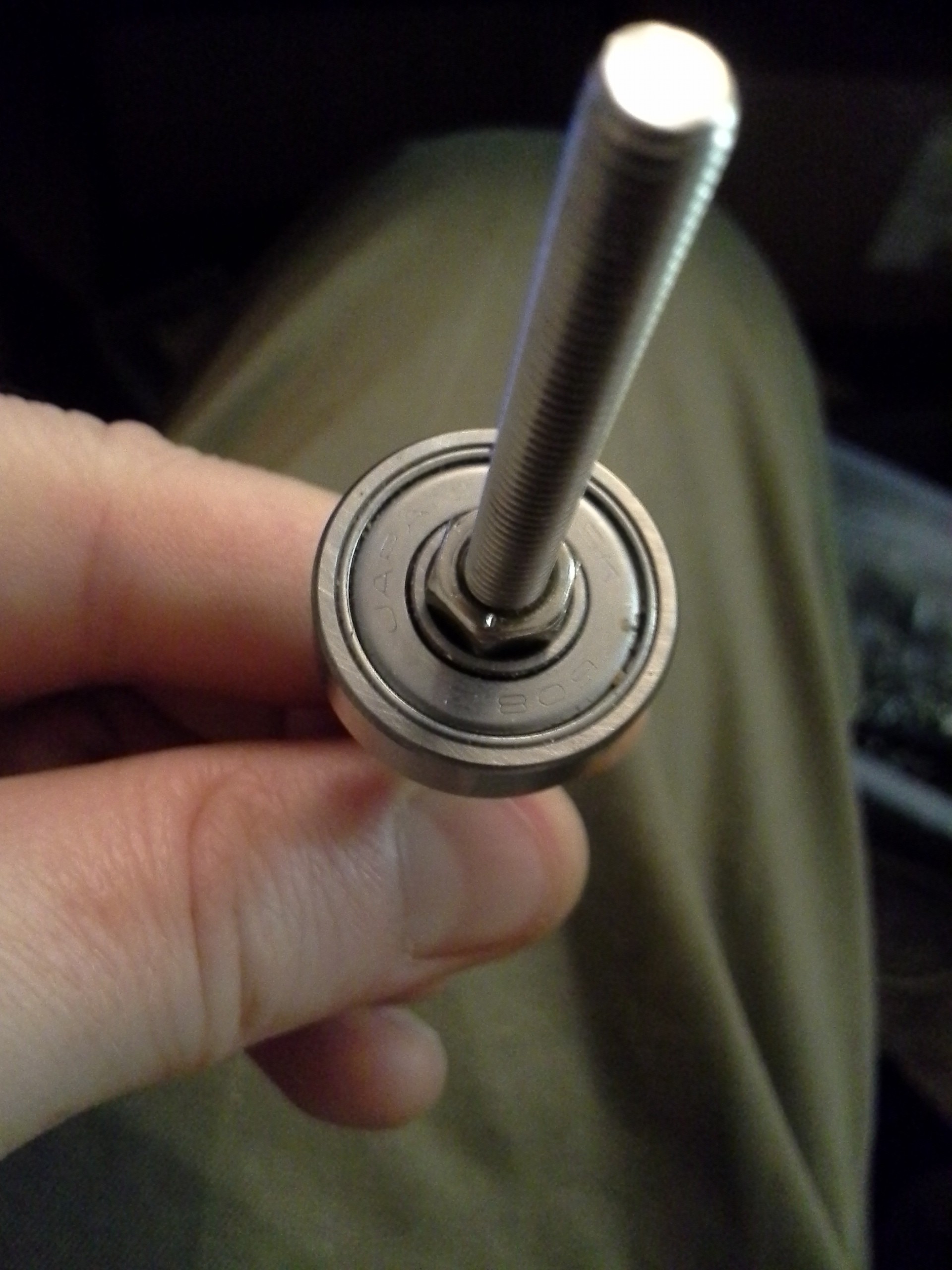
The bearing on the motor-end is held in place with three large-headed screws. The bearing on the "knob" end is held in place merely by friction and tension (wow!).
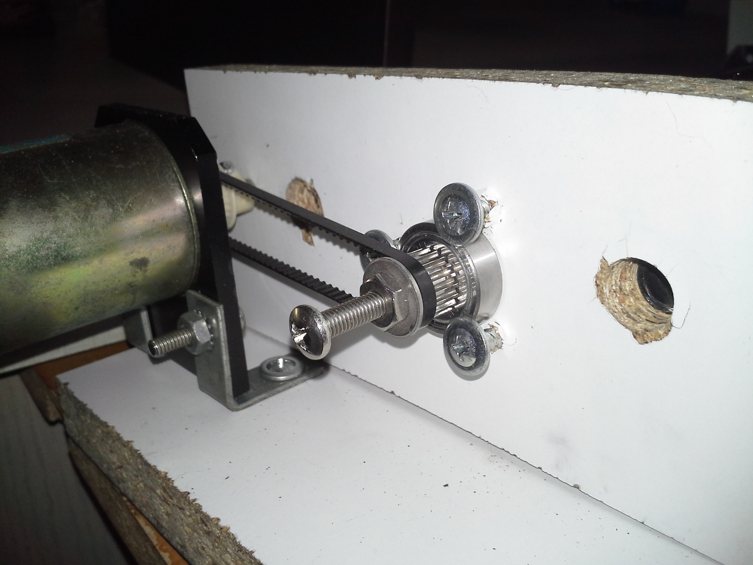
You can also see, quite clearly in this photo, just how accurately my electric saw cuts... Believe it or not, I mounted (and followed) a guide to cut a straight line, the blade managed to wander despite the guide. Wee! I've tried several attempts, several techniques... I'm pretty sure it's play in the saw. But it's good 'nough, eh?
-----------------
In the first picture you can see foam-core board at either end of the axis. (Thanks #Travelling Hacker Box! I never guessed how handy this stuff'd be!). I used it to find the center of the threaded-rod, once mounted in the carriage. I unscrewed the threaded-rod until it *just* protruded from the carriage, then slammed the carriage against the end-plate/foam-core. This put a nice divot in the foam-core. Then I poked through that with a pen-tip or something, and used that hole and the foam-core as a temporary bracket to hold the threaded-rod in position on both sides as I positioned the bearings, tightened nuts, etc.
The threaded-rod is attached to the carriage via a plate I made by hacksawing a triangular piece of aluminum...
Read more »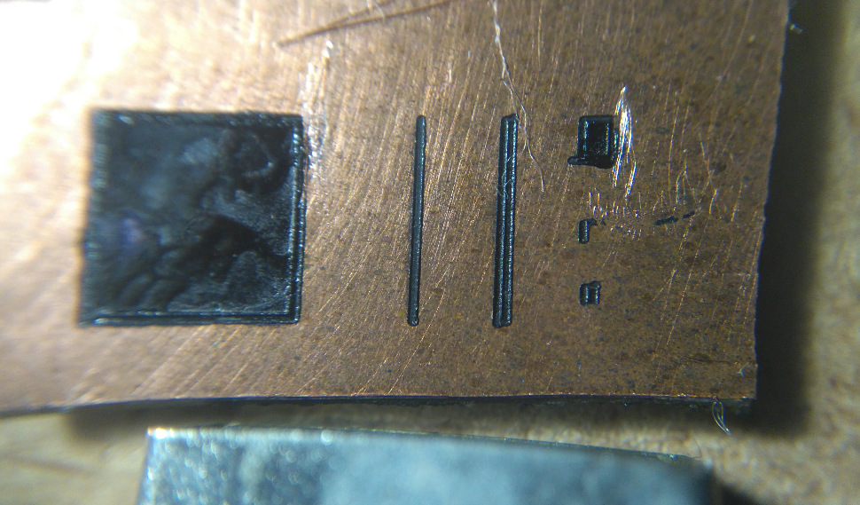


 zakqwy
Looking forward to seeing it move.