-
Building and uploading
12/25/2015 at 14:29 • 0 commentsSo you've got the code and the whole build environment is set up and configured.
Hitting verify (which is really just compile without uploading) gives you a nice output showing you the memory usage of the resulting code, based upon your chip memory -
Sketch uses 309,476 bytes (71%) of program storage space. Maximum is 434,160 bytes.
Global variables use 56,616 bytes (69%) of dynamic memory, leaving 25,304 bytes for local variables. Maximum is 81,920 bytes.
If you try to upload without things connected, and without a USB to serial TTL converter (3.3v compliaint) you'll get this -
warning: espcomm_sync failed
error: espcomm_open failed
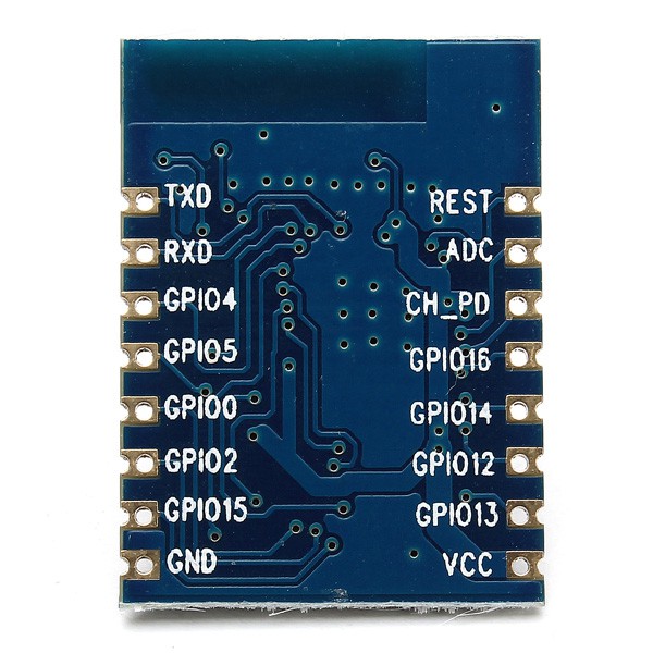
So now is time to put everything together. Below is a pic of the wiring for an ESP07 module. Be wary, this is from the underside, so you'll need to carefully mirror every pin horizontally when flipped over.![]()
For your particular variant, this arrangement of pins will vary wildly. I think you can complete this project with one of the ESP-01 modules, as all we need are -
- VCC
- GND
- TXD
- RXD
- REST
- GPIO2
- GPIO0
- GPIO15
Strictly speaking, GPIO15 is tied to ground on the ESP-01 so all is good here, and the REST pin is tied high to +3.3v I think (thru a resistor?).
I found a great resource online showing that the boot mode of the ESP is actually controlled with three GPIO pins -
GPIO0 GPIO2 GPIO15 UART Reflash mode 0 1 0 Start running from flash 1 1 0 SD Card Boot 0 0 1 This says it all, if you're reflashing your ESP, you should tie GPIO0 to ground, and tie GPIO2 to +3.3v. I think I just tied GPIO15 to ground. For my strip perfboard, I wired up an SPDT switch to GND, GPIO0, and +3.3v respectively, so as to control the boot mode, and allow reflashing even when installed in the hat.
You'll now need the USB to TTL Serial converter dongle. I had a nice 3.3v compliant model.
You should connect up like so -
USB To TTL Serial Converter ESP8266 (ESP-07) TXD RXD RXD TXD GND GND Just tell the Arduino dev environment which COM port your USB to Serial Converter is on, and it should work. You'll see a series of dots appear as it is uploading. Mine filled up one and two third rows with dots before it was finished.
The program will begin running immediately, but because the data output to the LEDs is on the RXD pin (it uses CNLOHR's I2S implementation, which uses this pin), it won't be going anywhere until you wire it up to your LED strips, and give them some power.
This does have the effect that the TXD pin on the ESP is still available, hence the Serial Monitor in the IDE environment can update you with debug info if required, even with the LEDs connected - as you can see my code is dotted with serial debug texts.
Although you've just seen your code run quite nicely if you wire in the WS2812s, if you power cycle the device, it'll not do anything because it's still in bootloader mode. Just flip the switch to run the code.
This is really all there is to it - that's why I love developing for the ESP8266, due to all the hard work building an Espressif native dev environment in Linux is now unnecessary, it opens the door to really rapid development from a Windows box (or Mac?).
-
Software
12/25/2015 at 12:54 • 0 commentsSo this article will go over the basics of the software, although all the real heavy stuff is done inside the various libraries.
I could do with a little help here actually, as the WiFi code is a little bit unreliable, possibly to do with a relatively large server.send() buffer - please feel free to look over the code and contribute.
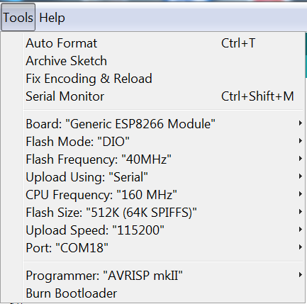
Firstly, Set up your build environment (Arduino 1.6.5) and get together all the various libs. The build and upload parameters are so -
![]()
I have no idea how much Flash memory my particular ESP-07 has, so I just set it to 512K, the lowest. It's currently running at 71% when compiled.
Notice how the chip is running at 160Mhz - this is double what is recommended, however it seems to work really well.
Basically just use the boards manager in the Arduino program to grab the ESP8266 build environment - For the record I'm using ESP8266 Community version 1.6.5-947-g39819f0. You may need to point the boards manager to a URL it can fetch the configuration from.
Also fetch the WS2812 Library from - https://github.com/JoDaNl/esp8266_ws2812_i2s. Add it into the Arduino libraries bit.
You should then be able to load in the Arduino Sketch and compile it fully.
Some points of note about the code -
- If you send a string via a web page form, it'll come out the other end with all spaces changed to + (interestingly not %20) and convert any non alphanumeric chars to a hex code, prefixed with a % char. The plus to space conversion is dead simple. This code below I knocked up quickly to do a simple conversion to a single char from the hex code representation. Because we've still got three chars to convert to a single char, to save mashing the string up I just set a special character of 127 to be a skipping char - the text scroller sees 127 and just moves straight away to the next char.
if(*p == '%') { *p = 127; //127 = skip char, see text_scroller() //This is an HTML represented HEX character condition - convert it to the actual character. int rslt = 0; p++; //Convert from Hex String to Int cos there's no avbl library routines I could find that don't hard reset the ESP8266! if(*p > '/' && *p < ':') rslt = 16 * (*p - 48); // between 0 and 9 if(*p > '@' && *p < 'G') rslt = 16 * (*p - 55); // between A and F *p = 127; p++; if(*p > '/' && *p < ':') rslt += (*p - 48); // between 0 and 9 if(*p > '@' && *p < 'G') rslt += (*p - 55); // between A and F Serial.print("output = "); Serial.println(rslt); *p = (char)rslt; } NOTE - I tried to use strtol(), but the Arduino implementation kept killing the ESP for some reason. This code is of course strictly reliant on all chars represented with %hexhex, a single byte, which it will be from a web page, I think! - To represent the character set, I wrote a small Windows program which allows you to draw a character in a 7x6 grid, and give you the C code to binary represent it -
char characters[128][6] = { { 0b01000000, 0b01000000, 0b01000000, 0b00000000, 0b00000000, 0b00000000 },
          { 0b01011111, 0b00000000, 0b00000000, 0b00000000, 0b00000000, 0b00000000 },
          { 0b00000011, 0b00000000, 0b00000011, 0b00000000, 0b00000000, 0b00000000 },
          { 0b00101000, 0b01111100, 0b00101000, 0b01111100, 0b00101000, 0b00000000 },
          { 0b01001000, 0b01010100, 0b11111110, 0b01010100, 0b00100100, 0b00000000 },
          { 0b01000110, 0b00110000, 0b00001100, 0b01100010, 0b00000000, 0b00000000 },
          { 0b00110100, 0b01001010, 0b01011010, 0b00100100, 0b01000000, 0b00000000 },
          { 0b00000011, 0b00000000, 0b00000000, 0b00000000, 0b00000000, 0b00000000 },
.
.
.
I then put together a whole section of the ASCII table in order, for easy referencing when constructing the graphics, currently excludes lower case chars. As can be seen, each line represents a single character, and they're just in a 2d char array. Very simple. Each byte is a vertical stripe of the character, and there are 6 pixels wide, so 6 bytes. - There is a function called 'SetupHTMLString()'. This is called in setup() only, it fills a C++ String with the full web page (only 1 page) as shown in the project gallery. It's surprisingly big considering it's only a table of colours and a very simple text input form. The WiFi libs don't like it this big at all, as it makes things a little unreliable building this large string every web request, so I decided to make the string a global var, and get the string populated early on, so the program doesn't have to keep reconstructing the string every time you server.send(...) the page. The string never changes. This does make the page much more reliable (Early on at least!), however I think I'm now falling foul of some garbage collection, or something, because after a while, the webserver decides to send back nothing if asked for it - I just get a 'no data received' error in the browser, in which I have to reset the chip. Any hints as to how to make this more reliable will be appreciated!
- During development it just joined my home WiFi network, which did seem to be a little more reliable than SoftAP mode, however it makes no sense making it a requirement to connect to your home network, as this is a WiFi hat, able to go anywhere, so it now creates an access point called 'LEDHat'. You then connect to it via the password set in code -
const char *ssid = "LEDHat";
const char *password = "YourPasswordHere";
You then point your browser towards 192.168.4.1, and you'll see the control page (See gallery image). You can simply click on any colour to instantly change the text colour as it scrolls, or enter a new string (so far up to 100 chars. Yes it's buffer overflowable very easily!!) and click 'Submit'. Obviously in future I intend on making animatable colours and other special effects, but if I've already hit the upper limit on server.send(), so I'll have to think about splitting into multiple pages. - I thought about using the cool mDNS feature they built into it, but it does require Bonjour on Windows to work - it basically allows you to just point your browser to a known name instead of an IP address, eg. esp8266.local. I have no idea whether it'd work on an Android smartphone, and it's no biggy just typing an IP Address in! I guess it would work on an iPhone though, as Bonjour is kind of an Apple thing. I think I freed up a whole percentage point of memory removing the mDNS components from the code, so it's a win!
- I like to keep code reasonably easy to understand wherever I can, so I represented the display code in simplistic terms, using a 2d matrix[x][y] array of WS2812 pixels type.
Pixel_t matrix[WIDTH][HEIGHT];Simply filling in the relevant pixel colour at the required coordinates will put that colour right there. Why make it tougher to understand? I'm sure there are much much more efficient ways of representing it, but because it's running at 160Mhz, I've managed to 'clock' the text scroller at well over 100+ frames per second. The display is only 18x7 after all. Can this really be called a 'frame buffer'!? - The code to render the display is pretty simple too -
void matrix_render(void) { //Render all channels composited together. int ct = 0; for(int y = 0; y < HEIGHT; y++) { for(int x = 0; x < WIDTH; x++) { pixels[ct++] = matrix[x][y]; } } ledstrip.show(pixels); } - So now all is required is to find a way of generating pretty visuals. I have a text colour variable, currently a global var. I've always been of the opinion that if you pass things around via function params, you're only adding to the workload of the CPU and stack memory, whereas modern 32 bit processors can easily reference globals without a single wasted CPU cycle or byte of RAM. I also consider these globals mostly read-only, up until a single 'authoritative' routine makes a change to it, perhaps only once an animation frame. This means thinking about code construction and being careful not to 'cross your streams' so to speak. This var is what the text scroller uses to update the pixels in the 'frame buffer'.
- So the text_scroller() routine just carefully manages which character within the text string it is currently rendering (charpos), plus which column of pixels it's working with (subcharpos) in that character. Between animation frames the whole routine drops out back to loop() so it needs to persistently keep track of where it is via these two vars. It simply scrolls the whole display one pixel to the left - notice the careful ordering of X and Y loops, and copying right side data to the left, so as not to overwrite needed data as we copy it around -
    //Scroll the whole layer to the left
    for (x = 0; x < WIDTH - 1; x++)
    {
        for (y = 0; y < HEIGHT; y++)
        {
          matrix[x][y] = matrix[x + 1][y];
        }
    }
blanks the pixels on the right edge,//Reset the rightmost column to blank for (y = 0; y < HEIGHT; y++) { matrix[WIDTH - 1][y].R = 0; matrix[WIDTH - 1][y].G = 0; matrix[WIDTH - 1][y].B = 0; }then constructs the rightmost column of pixels from the character set -if(spacechr == false) { tmp2 = coldata & 0x01; if(tmp2 == 0x01) matrix[WIDTH - 1][HEIGHT - 7] = textcolour; tmp2 = (coldata >> 1) & 0x01; if(tmp2 == 0x01) matrix[WIDTH - 1][HEIGHT - 6] = textcolour; tmp2 = (coldata >> 2) & 0x01; if(tmp2 == 0x01) matrix[WIDTH - 1][HEIGHT - 5] = textcolour; tmp2 = (coldata >> 3) & 0x01; if(tmp2 == 0x01) matrix[WIDTH - 1][HEIGHT - 4] = textcolour; tmp2 = (coldata >> 4) & 0x01; if(tmp2 == 0x01) matrix[WIDTH - 1][HEIGHT - 3] = textcolour; tmp2 = (coldata >> 5) & 0x01; if(tmp2 == 0x01) matrix[WIDTH - 1][HEIGHT - 2] = textcolour; tmp2 = (coldata >> 6) & 0x01; if(tmp2 == 0x01) matrix[WIDTH - 1][HEIGHT - 1] = textcolour; //tmp2 = (coldata >> 7) & 0x01; //if(tmp2 == 0x01) matrix[WIDTH - 1][HEIGHT - 1] = textcolour; }Yes it's pretty ugly, pretty inefficient I'm sure, but I've not yet ran into any performance issues. It picks out coldata and ANDs it with a binary 1 to pick out that particular pixel in the column, tests it against 1 (it's only 1 bit/pixel) then if so, sets it to the current text colour - that way your 1 bit colour can be any colour you choose. It does this for each pixel in the column one pixel at a time with an unrolled loop. Notice how it bit shifts ( coldata >> #) to pick out the relevant bit from the character set at that point. - The main loop is very simple -
void loop()
{
  static int txtscrl = 0;

  server.handleClient();

  HandleColourChange();

  text_scroller();

  matrix_render();

  HandleTextChange();

  delay(1000 / FPS);

}
I find it is always key to keep the software ticking over pretty permanently without ridiculous delay() calls all over the place. If you have time critical code that shouldn't be called twice in one animation frame update, then just exit until your CPU time count (millis()) has gone over a certain value. Luckily the WiFi libraries do all of their work during delay() calls, so it's actively encouraged to use them just to keep the WiFi responsive. Regardless, the delay() call at the end of the loop keeps it fixed to the pre-determined FPS define, currently only 17fps due to the text scrolling speed. This gives the WiFi code plenty of spare CPU cycles to do it' The server.handleClient() is another obvious way for the WiFi libraries to 'keep up'. HandleColourChange() is a way I previously had to animate the text colour, and will be utilised in future for a rainbow effect, I'm sure. - HandleTextChange() is admittedly a bit of an odd one. I was concerned about how updating the text box with some new text might disrupt my text_scroller() function - if the WiFi code disrupted the contents of the txt variable while the scroller was accessing it, all hell could break loose, so I did a kind of a 'double buffering' of the text field.
void HandleTextChange()
{
  if(textchanged == true)
  {
    strcpy(txt, newtxt);
    charpos = 0;
    subcharpos = 0;
    texthold = 0;
    textchanged = false;
  }
}
I wanted the TextScroller() to definitely not be acting on the data while the text buffer was being changed over, so this happens outside of that routine every frame. When you submit a new line of text, it goes into a completely independent text buffer, newtxt. See line 7 below -void handleSubmit() { if (server.args() > 0 ) { for ( uint8_t i = 0; i < server.args(); i++ ) { if (server.argName(i) == "displaytext") { // do something here with value from server.arg(i); server.arg(i).toCharArray(newtxt,99); for (char *p = newtxt; *p != '\0'; ++p) { *p = toupper(*p); //No lower case chars represented (yet) so convert to upper across whole string. if(*p == '+') *p = ' '; //Convert HTML + chars to spaces. if(*p == '%') { *p = 127; //127 = skip char, see text_scroller() //This is an HTML represented HEX character condition - convert it to the actual character. int rslt = 0; p++; //Convert from Hex String to Int cos there's no avbl library routines I could find that don't hard reset the ESP8266! if(*p > '/' && *p < ':') rslt = 16 * (*p - 48); // between 0 and 9 if(*p > '@' && *p < 'G') rslt = 16 * (*p - 55); // between A and F *p = 127; p++; if(*p > '/' && *p < ':') rslt += (*p - 48); // between 0 and 9 if(*p > '@' && *p < 'G') rslt += (*p - 55); // between A and F Serial.print("strtol output = "); Serial.println(rslt); *p = (char)rslt; } } textchanged = true; //Handle the change somewhere else where we guarantee it's not drawing text as we change the string. //Serial.print("Got some new text - "); //Serial.print(server.arg(i)); //Serial.print(" converted to char array looks like - "); //Serial.print(txt); } } } }During the critical point when HandleTextChange() is called, it is string copied into the real scroll buffer, then all the relevant text scroll state vars are reset, so as to restart the whole process. It turned out to be a little too efficient, as it doesn't do anything with the scroll position, or add it after a few spaces, it just starts scrolling the next text the instant it is changed over - this has the effect of making the text change-over point difficult to read! Oh well, I could add in something to space it all out I suppose with a little more effort.
- If you send a string via a web page form, it'll come out the other end with all spaces changed to + (interestingly not %20) and convert any non alphanumeric chars to a hex code, prefixed with a % char. The plus to space conversion is dead simple. This code below I knocked up quickly to do a simple conversion to a single char from the hex code representation. Because we've still got three chars to convert to a single char, to save mashing the string up I just set a special character of 127 to be a skipping char - the text scroller sees 127 and just moves straight away to the next char.
-
Power calculations?
12/24/2015 at 22:23 • 0 commentsI'm a little surprised right now. I've just done a very simple power calculation for the strips and something is awry. Assuming each LED claims 60mA at full brightness (probably a little lower if driven at 4.2v?), and there are 18 columns by 7 rows.
This makes 7.56Amps max drain, full white.
Could this display possibly claim 31.7 watts (4.2v) maximum!?
I'm not sure how I came to the conclusion that only two of these buck converters are required if they're only rated at 10w, 2 amps (3 maximum).
Oh well, I guess I shouldn't be driving it at full brightness, but I can get close.
But even for the really modest power requirements of a simple text scroller, my code currently only drives at half the full brightness (R127 G127 and B127 at white) as it's still really bright because of the dark winter right now! I guess I'll stick to only using 50% of the range throughout.
At some point I'll do some real power calculations with a test program and an ammeter.
-
Physical Build
12/24/2015 at 21:35 • 0 commentsThis bit done most recently, so I'll document it first.
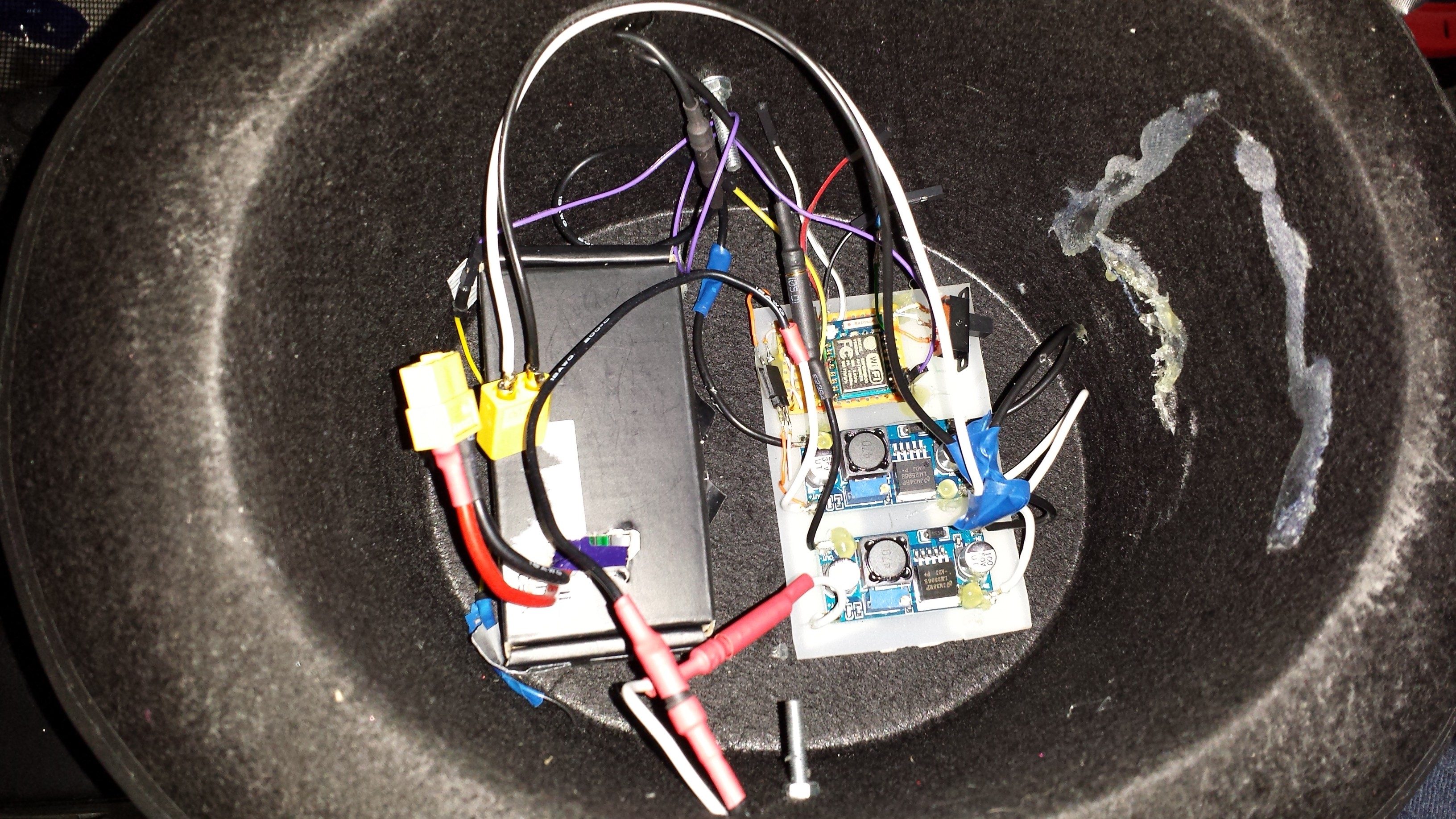
![]()
So here is the all-important interior. From this view, the left of the hat is the front.
To point out all the bits and pieces, from left to right -
- The cardboard box the RC battery came in! Strengthened a little with some duct tape, re-openable to replace and recharge the battery, seems to hold it in well. All stuck down with some double sided foam tape.
- A piece of acrylic sheet, stuck down with more double sided foam tape. It is cut down to size to accommodate the DC-DC buck converters, plus a small strip perfboard with which I mounted the 3.3v regulator, ESP8266, a switch for changing between chip program / run modes, and a 3 pin 0.1" header for programming / driving the LEDs. That's the smallest switch I had!
- NOTE - The ESP-07 is of course not 0.1" pin pitched, so I ran copper wires from some stripped CAT5 wires and just connected it all up, getting as close as I can to laying it flat against the perfboard without shorting wires.
- As you can see there's some hot glue residue on the rear wall, this was a failed attempt at mounting the battery on a side wall using some soft material. Turns out it presses against my head when you put it on!
- Wires all over the place, although I do use connectors instead of permanent solder points wherever possible - I've soldered up things and had to dismantle it again when something goes wrong way too many times!
- Various RC motor bullet connectors (heat shrink colour coded for + and -) and an XT-60 battery connector. To dismantle the display from the hat, just unplug all the bullet connectors, disconnect the long thin purple data cable, unscrew the two bolts, push in the sides of the hat, and slide the display forward, being careful not to snag the connectors in the holes.
Why am I using two buck converters? Well because one alone most certainly won't be enough to drive all the LEDs at full brightness, being rated at only 10w each. I power four rows with one, and three rows and the ESP8266 board with the other.
Point of note - I set the buck converters to provide only 4.2volts. Why? Well because the strips are still awesomely bright when fully illuminated at 4.2v, and it allows the 3.3v data signal to work. Ever since I started working with WS2812s over a year ago, I've tried to drive them at 5v with a 3.3v controller (Raspberry Pi's included), many people say it works, or should work, but for me it hasn't worked (reliably) without some kind of voltage boost on the data signal, usually a Logic Level converter. I've also fallen foul of an initial surge, killing the first or second LEDs in the chain as it turns on at 5v (perhaps surging to 7v or 8v). A bad PSU? Probably, but at 4.2v I've never had to worry about it!
The bolts were literally hot glued, head first, onto the left and right inside edges of the 3D printed LED mount pointing inwards, then poked through the aforementioned holes. A washer and nut are done up to ensure a tight fit. I took extra care when poking holes in the hat for these attachment points to make sure I got them in the right place.
There is no connection point on the front of the 3D printed mount, even with the nuts and bolts done up tightly, so it can still rotate up and down a little, kind of like how a helmet visor rotates. This isn't a real problem though as it would only happen when nodding aggressively!
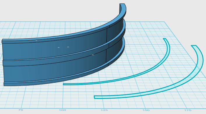
As for the 3D printed mount, this is literally a 3D model curved around the hat brim, with a 'recess' for putting in the LED strips, and they are spaced vertically to allow a nice line-up pattern of LEDs throughout.
I used the brilliant Autodesk 123D design program to knock up some half-curve 2D shapes, matched to the curvature of the hat (using trial and error). I produced a thick one and a thin one, then extruded and stacked each at various points vertically, using careful measurements of the 'pixel pitch' to ensure a nice square pixel pitch arrangement. At the top you need to measure it correctly to be vertically stackable without disrupting the spacing.![]()
When printing it out, you have to mirror duplicate this shape to go around 180 degrees, then print it out four times. I then simply duct taped the pieces vertically, inside edge only. Because it's 180 degrees round, the duct tape holds the shape solidly.
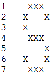
Four prints produce eight rows for the LED strips, but I'm using only 7, so the bottom one is left unoccupied to account for the hat brim, which would otherwise block from view the bottom strip of LEDs. Why 7 rows? Well because it's primarily a text scroller display. 7 rows makes for a nice font allowing for upper and lower case characters (although I've only so far implemented upper case characters), eg -
![]()
Each of the LED strips are simply removed from the reel, cut off at 18x LEDs (I originally went with 19x horizontally, but ran into a wiring issue getting them all nicely supported without pulling out the solder joints on the far edges), then the sticky backing is removed and laid onto the mount, ensuring a snug touch with the bottom 'shelf' of each row. A little bit of horizontal nudging helped them all line up.
A pretty unpleasant lengthy soldering process was involved wiring up all the strips, as the small copper pads weren't particularly solder compliant on the top surface, especially seeing as I had to remove some of the weather protective transparent stuff. I ended up soldering up the underside copper contact points instead.
As for the wiring arrangement - I wired up +4.2v to the LEFT side of each strip, and the 0v to the RIGHT side of each strip, all using CAT5 copper. The data connections are arranged left to right, row per row, typewriter style, giving me an easy coding job mapping pixels to X,Y coordinates - pixelnum = (y * 18) + x.
That's about it for the physical build! A lot of overall detail is included here.
LED WiFi Hat
A self-contained, fully cusomisable LED display board on a hat, WiFi enabled for Web based setup.