-
1Step 1
Remember that this sits at high voltage. Do not connect the Arduino to the computer while lights are plugged in.
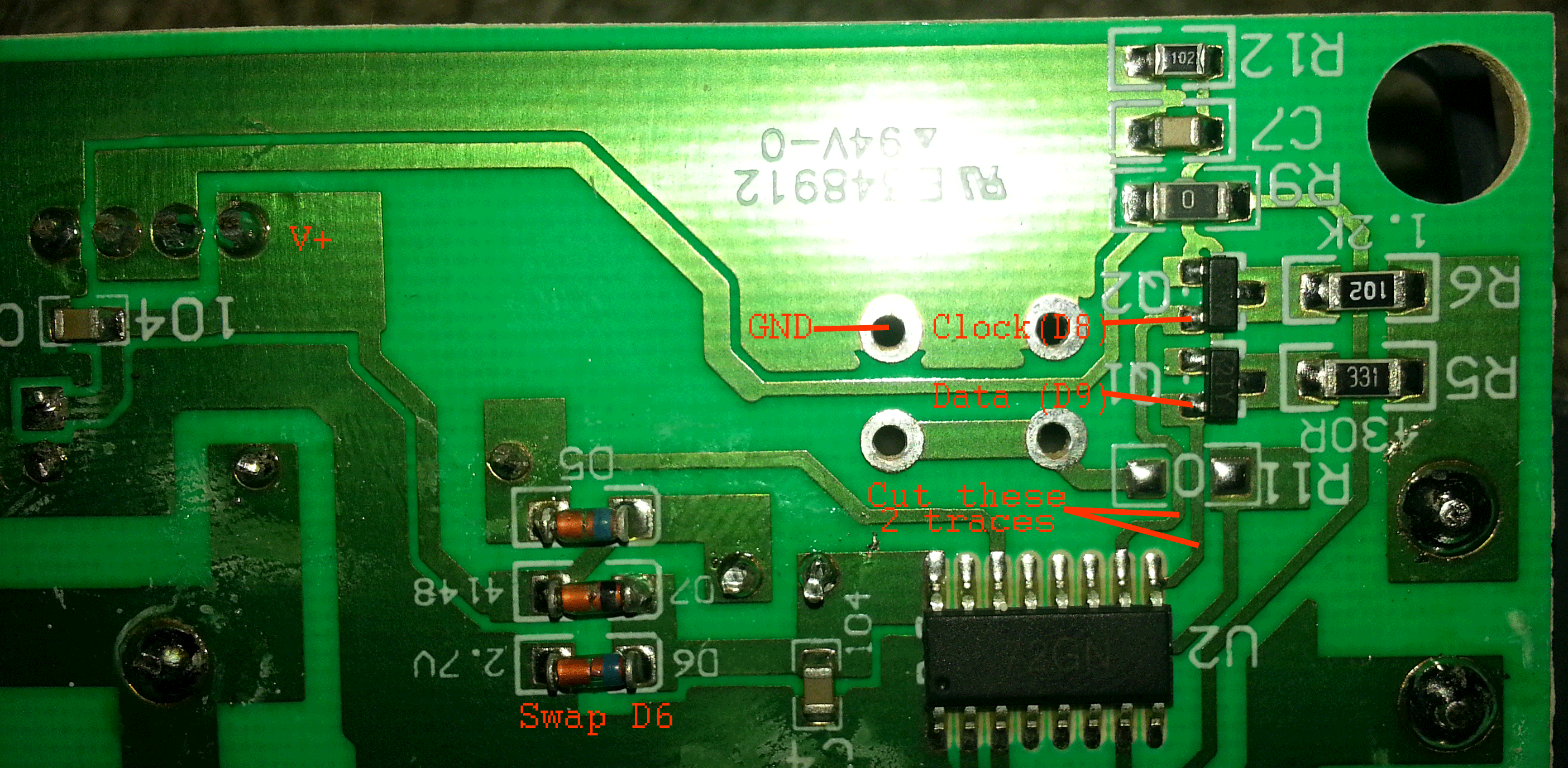
Basically this works by cutting the traces from the MCU and using the arduino in its place.
![]()
D6 needs to be changed to at least a 5V zener diode. This makes the part labeled V+ at about 3.1V. A slightly larger Zener Might be beneficial. V+ connects to the Arduino 5V and GND connects to the arduino GND. The data line connects to the Arduino D9 pin and the clock line connects to the Arduino D8 pin
-
2Step 2
Serial Optoisolator instructions to follow
Addressable Christmas Lights 2015
My search for a replacement to the GE G35 lights
Discussions
Become a Hackaday.io Member
Create an account to leave a comment. Already have an account? Log In.