-
1Step 1
Connecting the HDMI Switch
I found 2 kinds of hdmi switches :
-mechanic ones which consist of a strictly mechanical switching process
-digital ones where all the inputs go to a chip that will pick one for output. Some of them come with a remote.
I went for a digital one with a remote. This way I don't even have to get a remote for my raspberry pi.
The switch has both a remote and a button, it also has leds that indicate which HDMI input is selected.
It doesn't require any external power source as it is supposed to be powered by the HDMI devices it is connected to.
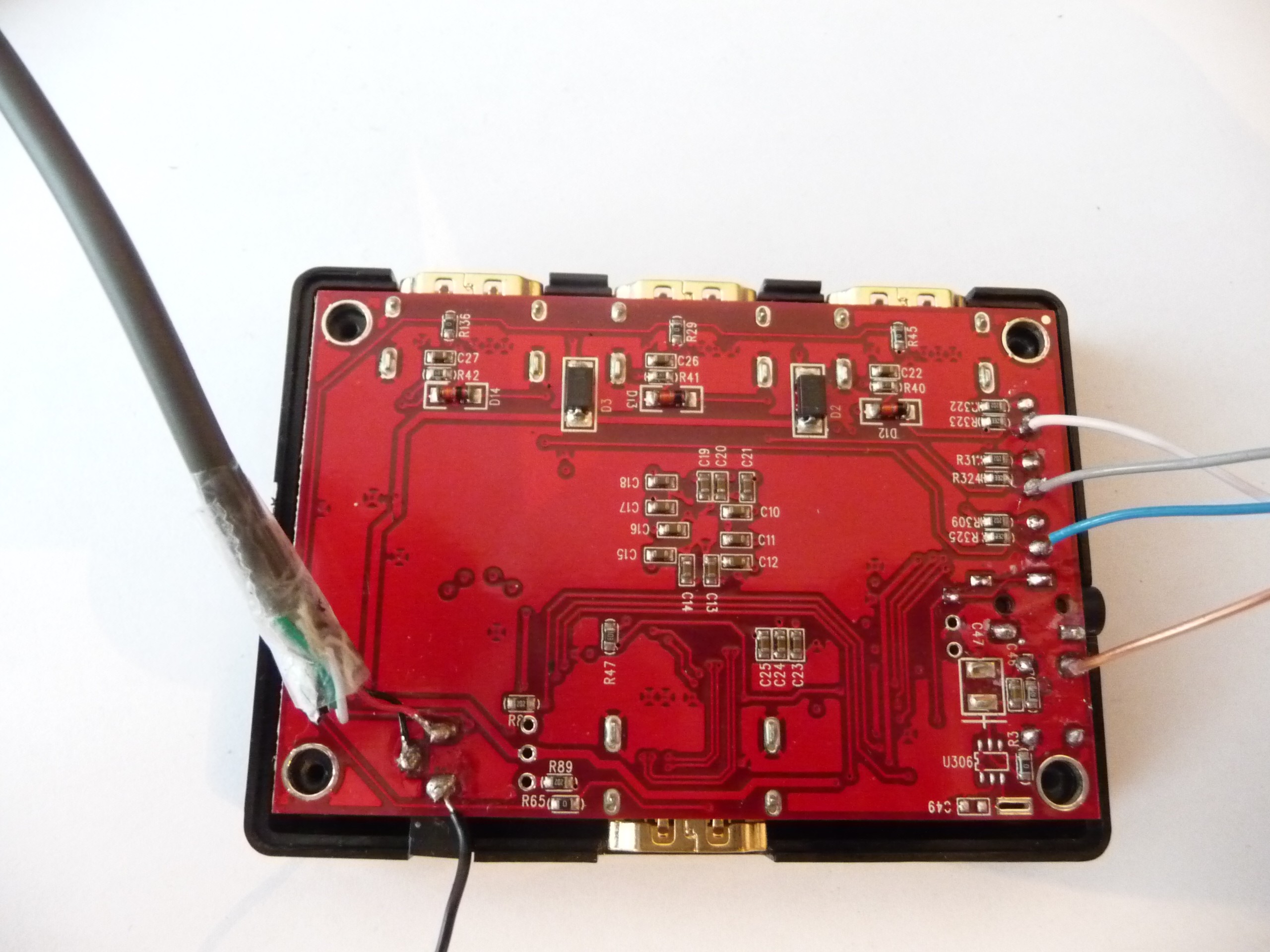
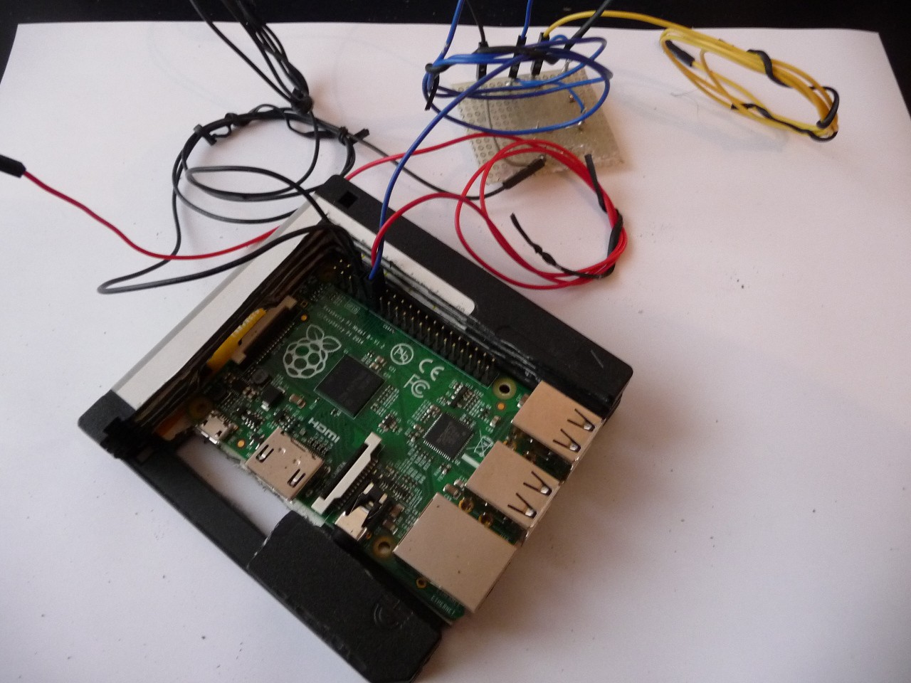
I tried to make as few modifications as possible to keep the HDMI switch orginal behaviour but I soldered a USB plug so I can make my tests without any HDMI devices connected.
Otherwise I just soldered wires to read the LED values and to simulate a the "next HDMI input" button being pressed![]()
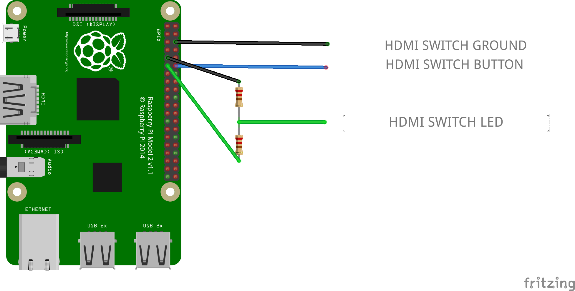
- GPIO 17, PIN 11, is connected to the HDMI switch led ( and a resistor bridge to lower the voltage to 3.3v)
- GPIO 18, PIN 12 is connected to the HDMI switch button
So let's say we have the following setup :
- HDMI switch input port 1 : RPi
- HDMI switch input port 2 : STB
- HDMI Led output pin connected to GPIO : 1
- Button to use on the remote : 1
The system should be started with HDMI port 2 active -
2Step 2
Software for controlling the HDMI switch
First you need to install WiringPi
if your distribution has a package for it just do a
sudo apt-get install wiringpiotherwise you'll have to follow the instructions here.we can control the GPIO from the shell with /usr/local/bin/gpio. Here are 3 scripts you can use:
init_hdmi_switch.sh
#! /bin/sh
gpio mode 0 in
gpio mode 1 out
gpio write 1 1
get_hdmi_port.sh
#! /bin/sh
gpio read 0
switch_hdmi.sh
#! /bin/sh
gpio write 1 0
sleep 0.2
gpio write 1 1
This is a bit confusing because by default it uses the WiringPi pin numbering, so 0 is pin 17 and 1 is pin 18. Also to simulate a button press, we have to set the pin to low for 0.2 seconds and then to high again. 0.2 scond is an empirical value that works reliably for me, it probably depend on your switch model.
Usage:
- first launch init_hdmi_switch.sh to configure the GPIO
- launch hdmi_switch.sh to switch to another hdmi port
- launch get_hdmi_port.sh, it will return 1 if the hdmi port 1 is active ( port 1 or any port you soldered the GPIO to) and 0 otherwise
-
3Step 3
Floppy up!
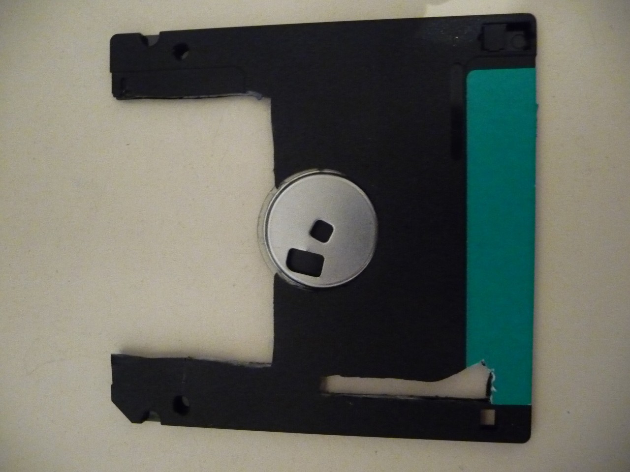
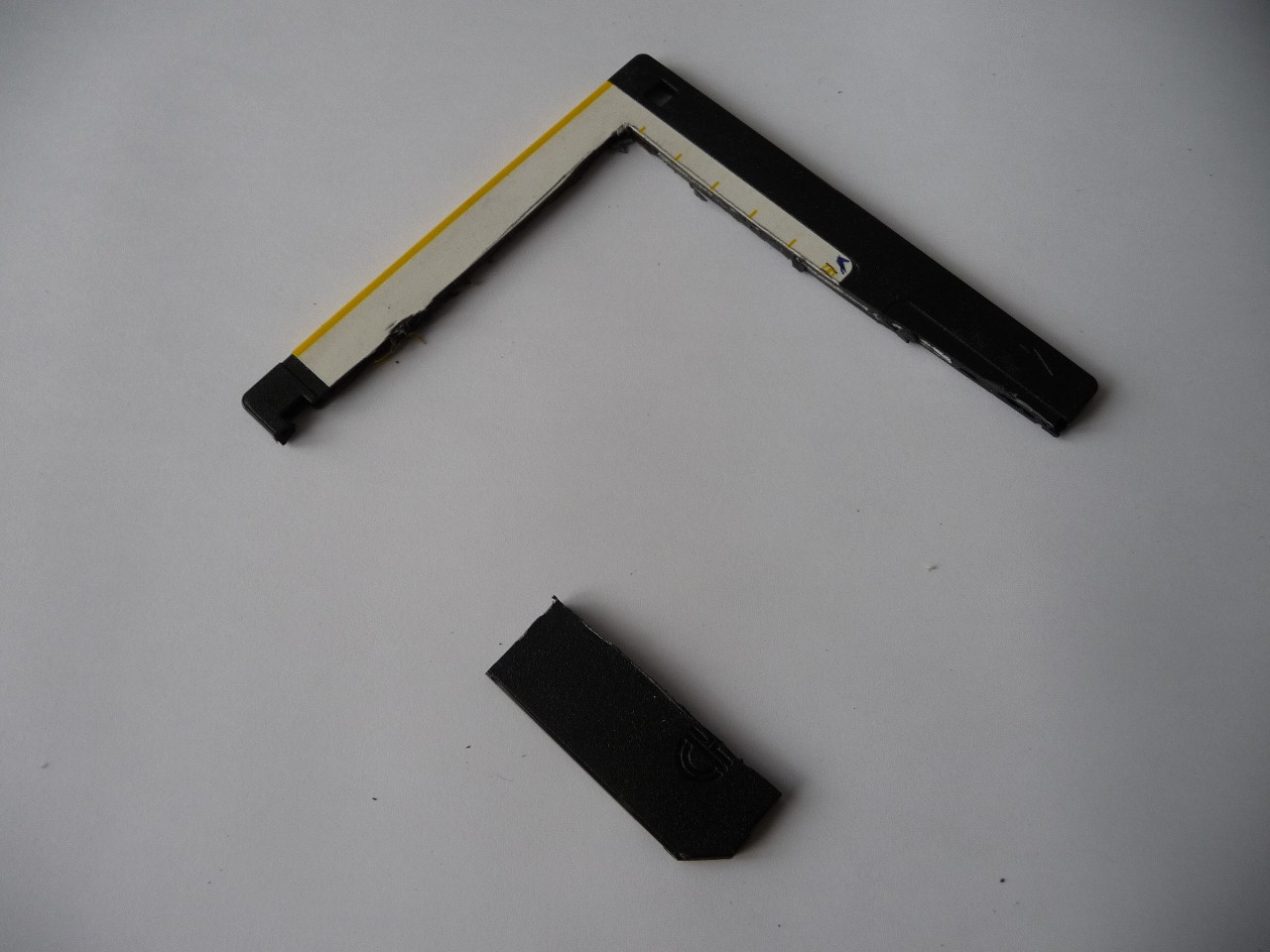
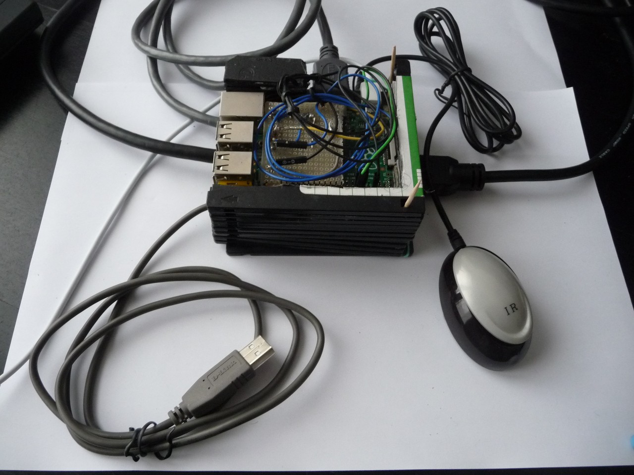
As a temporary solution and to make good use of 3"5 floppies laying around, I carved floppy disks with a Dremel and used a glue pistol to assemble all of it into a case for my raspberry pi and my HDMI switch.
Cutting the floppies was not very fun, there was a strong smell of molten plastic. I'm not sure it is very healthy.
Bottom part for the HDMI switch, with a room for the HDMI cables an a thin line for the ledsan the button on the switch
The Raspberry Pi B+ has ports on nearly every sides, not much of the floppy is left...
A stack with the HDMI switch, the Raspberry pi and the resistor bridge.
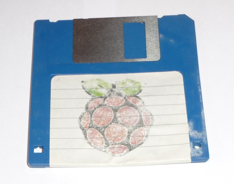
The Raspberry Pi logo was printed with a laser printer on a standard A4 sheet and then I took a regular iron (for clothes, not for soldering!) to print it on the top floppy lid.
Tecedi SmartZap: Adblock for TV
Control a HDMI switch with your Raspberry Pi and watch something interesting during TV ads.
 PixJuan
 A stack with the HDMI switch, the Raspberry pi and the resistor bridge.
Discussions
Become a Hackaday.io Member
Create an account to leave a comment. Already have an account? Log In.