Hari Wiguna
-
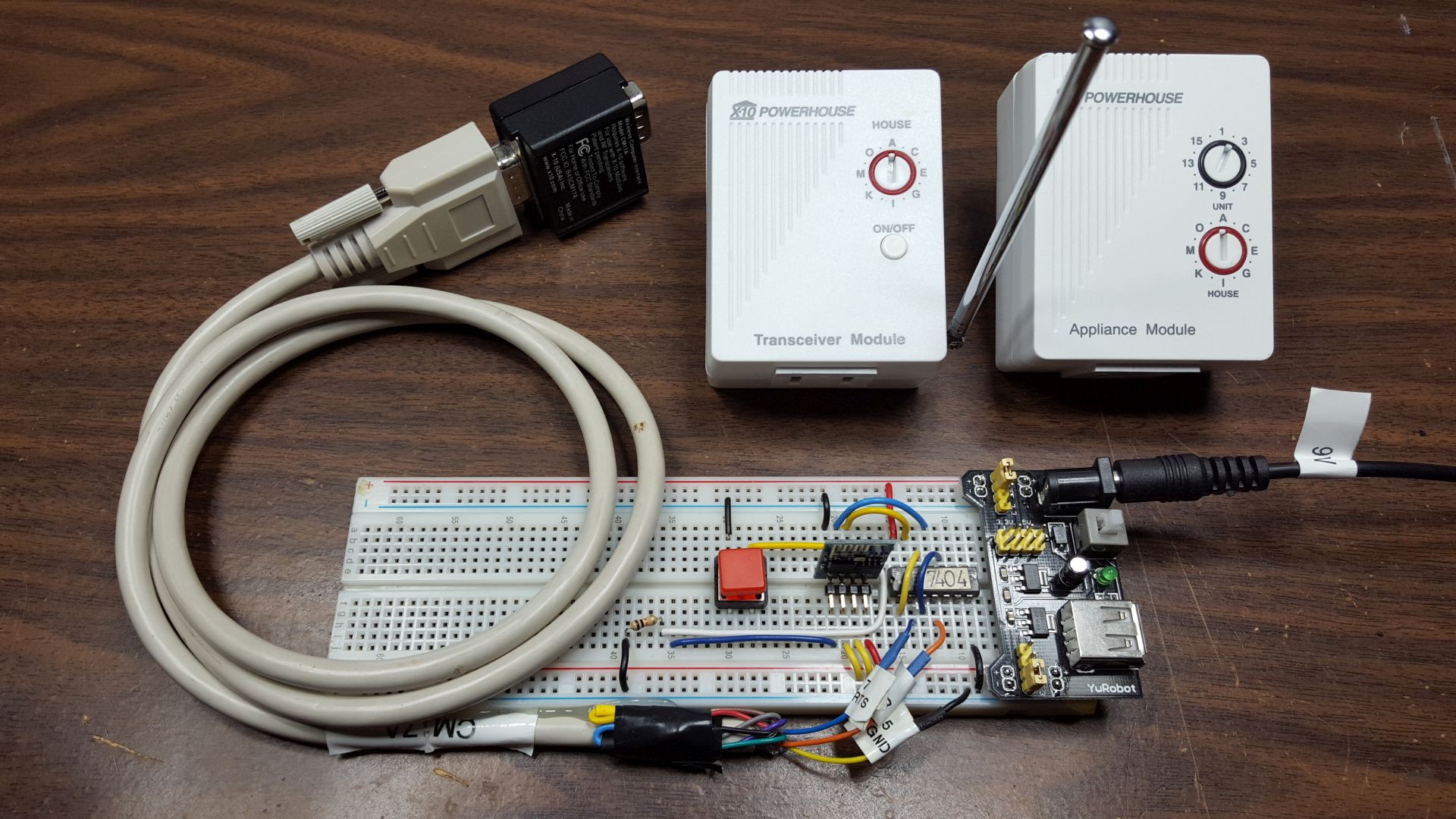
Amazon Echo from 2015 meets X-10 from 1978!
01/07/2016 at 02:08 • 4 comments![]()
Sketch and wiring for Arduino can be found here. I connected ESP's GPIO0 to RTS and GPIO2 to DTR of the CM17A. Each goes through TWO inverter gates (in the SN7404 TTL chip) to convert the 3.3V signals to 5V.
The code below subscribes to MQTT button push from Adafruit.io instead of polling it from the ESP.
I commented out the ping from loop() because it sometimes would flush the MQTT packet from the server if it pings just at the wrong time. So, I let it timeout and it would reconnect when it discovers that it's no longer connected to the server.
I also modified Brohogan's excellent code to work on the ESP8266 by not relying on ATMega specific code.
// Amazon Echo meets X-10
// Hari Wiguna, 2016
//
// Hacked together from:
// - Adafruit MQTT Library ESP8266 Example
// - and http://playground.arduino.cc/X10/CM17A

#include <ESP8266WiFi.h>
#include "Adafruit_MQTT.h"
#include "Adafruit_MQTT_Client.h"
#include <X10Firecracker.h> // Use the modified version of this that no longer rely on ATMega specific features. -- Hari

// Configurations
#define AIO_SERVER      "io.adafruit.com"
#define AIO_SERVERPORT  1883
#define AIO_USERNAME    "?????"
#define WLAN_SSID  "Firefly24"
#define WLAN_PASS  "?????"
#define AIO_KEY    "?????"

int ledPin = 2;
bool isDebug = false; // Don't debug if USB serial is not connected

// Create an ESP8266 WiFiClient class to connect to the MQTT server.
WiFiClient client;

// Store the MQTT server, username, and password in flash memory.
// This is required for using the Adafruit MQTT library.
const char MQTT_SERVER[] PROGMEM    = AIO_SERVER;
const char MQTT_USERNAME[] PROGMEM  = AIO_USERNAME;
const char MQTT_PASSWORD[] PROGMEM  = AIO_KEY;

// Setup the MQTT client class by passing in the WiFi client and MQTT server and login details.
Adafruit_MQTT_Client mqtt(&client, MQTT_SERVER, AIO_SERVERPORT, MQTT_USERNAME, MQTT_PASSWORD);

/****************************** Feeds ***************************************/
// Setup a feed called 'light' for subscribing to changes.
const char ONOFF_FEED[] PROGMEM = AIO_USERNAME "/feeds/light";
Adafruit_MQTT_Subscribe onoffbutton = Adafruit_MQTT_Subscribe(&mqtt, ONOFF_FEED);

/*************************** Sketch Code ************************************/

void setup() {
  X10.init( 0, 2, 5 ); // 0=RTS, 2=DTR, 5=extra delay for faster ESP8266

  if (isDebug) Serial.begin(115200);
  delay(10);

  if (isDebug)
  {
    Serial.println(F("Adafruit MQTT demo"));

    // Connect to WiFi access point.
    Serial.println(); Serial.println();
    Serial.print("Connecting to ");
    Serial.println(WLAN_SSID);
  }

  WiFi.begin(WLAN_SSID, WLAN_PASS);
  while (WiFi.status() != WL_CONNECTED) {
    delay(500);
    if (isDebug) Serial.print(".");
  }

  if (isDebug)
  {
    Serial.println();

    Serial.println("WiFi connected");
    Serial.println("IP address: "); Serial.println(WiFi.localIP());
  }

  // Setup MQTT subscription for onoff feed.
  mqtt.subscribe(&onoffbutton);
}

// Function to connect and reconnect as necessary to the MQTT server.
// Should be called in the loop function and it will take care if connecting.
void MQTT_connect() {
  int8_t ret;

  // Stop if already connected.
  if (mqtt.connected()) {
    return;
  }

  if (isDebug) Serial.print("Connecting to MQTT... ");

  while ((ret = mqtt.connect()) != 0) { // connect will return 0 for connected
    if (isDebug) {
      Serial.println(mqtt.connectErrorString(ret));

      Serial.println("Retrying MQTT connection in 5 seconds...");
    }
    mqtt.disconnect();
    delay(5000);  // wait 5 seconds
  }
  if (isDebug) Serial.println("MQTT Connected!");
}
void loop() {
  // Ensure the connection to the MQTT server is alive (this will make the first
  // connection and automatically reconnect when disconnected).  See the MQTT_connect
  // function definition further below.
  MQTT_connect();

  // this is our 'wait for incoming subscription packets' busy subloop
  Adafruit_MQTT_Subscribe *subscription;
  while ((subscription = mqtt.readSubscription(3000))) {
    if (subscription == &onoffbutton) {
      if (isDebug) {
        Serial.print(F("Got: "));
        Serial.println((char *)onoffbutton.lastread);
      }

      if (strcmp((char*)onoffbutton.lastread, "OFF") == 0) {
        X10.sendCmd( hcA, 1, cmdOff );
        //digitalWrite(ledPin, HIGH);
      }
      if (strcmp((char*)onoffbutton.lastread, "ON") == 0) {

        X10.sendCmd( hcA, 1, cmdOn );
        //digitalWrite(ledPin, LOW);
      }
    }
  }

  // I find it more reliable to let mqtt timeout and reconnect. ping flushes buffer causing packet loss -- Hari
  // ping the server to keep the mqtt connection alive
  //if (! mqtt.ping()) {
  //  mqtt.disconnect();
  //}
  //delay(1000);
}
X10Firecracker.h
/* Arduino interface to the CM17A Wireless X10 'Firecracker' dongle.
	BroHogan 7/19/08
	DaveK AC0KG Dec/08
	Hari Wiguna Jan/16
 */

#ifndef X10Firecracker_h
#define X10Firecracker_h
#include <stdint.h>

enum HouseCode { hcA, hcB, hcC, hcD, hcE, hcF, hcG, hcH,
				 hcI, hcJ, hcK, hcL, hcM, hcN, hcO, hcP };

enum CommandCode { cmdOn, cmdOff, cmdBright, cmdDim };

class X10Firecracker {
public:
	int RTS_pin;    // RTS line for C17A - DB9 pin 7
	int DTR_pin;    // DTR line for C17A - DB9 pin 4
	int Bit_delay;  // mS delay between bits (0.5mS min.)

	X10Firecracker();

	void init( int RTS_Pin, int DTR_Pin, int Bit_Delay );
	void sendCmd(HouseCode house, int device, CommandCode cmnd);
};

extern X10Firecracker X10;

#endif
X10Firecracker.cpp -- modified so it would run on the ESP8266
/* Arduino Interface to the CM17A Wireless X10 dongle. BroHogan 7/19/08
* Arduino Library Conversion by DaveK AC0KG
* Modified for ESP8266 by Hari Wiguna, 2016
*
* The CM17A gets it power and data using only the RTS, CTS, & Gnd lines.
* A MAX232 is not req. (0/+5V work OK) If MAX232 IS used reverse all HIGHs & LOWS
* Signal      RTS DTR        Standby | '1' | Wait | '0' | Wait | '1' | Wait...
* Reset        0   0         _____________________       _____________________
* Logical '1'  1   0   RTS _|                     |_____|
* Logical '0'  0   1         ________       ___________________       ________
* Standby      1   1   DTR _|        |_____|                   |_____|
*
* MINIMUM time for the '1', '0' and 'Wait' states is 0.5ms.
*
* At least one signal must be high to keep CM17A powered while transmitting.
*
* Each xmit is 40 bits -> "Header" 16 bits,  "Data" 16 bits, "Footer" 8 bits
*
* CONNECTION: RTS -> DB9 pin 7
*             DTR -> DB9 pin 4
*             Gnd -> DB9 pin 5
*/

//#include <avr/pgmspace.h>
#include <arduino.h>

#include "X10Firecracker.h"

// An instance of the EventFuse class
X10Firecracker X10 = X10Firecracker();

// This will generate a warning "only initialized variables can
// be placed into program memory area". Apparently this is a compiler
// bug, can't do much about it.
const uint16_t houseCode[] = {
	0x6000,  // A
	0x7000,  // B
	0x4000,  // C
	0x5000,  // D
	0x8000,  // E
	0x9000,  // F
	0xA000,  // G
	0xB000,  // H
	0xE000,  // I
	0xF000,  // J
	0xC000,  // K
	0xD000,  // L
	0x0000,  // M
	0x1000,  // N
	0x2000,  // O
	0x3000,  // P
};

// This will generate a warning "only initialized variables can
// be placed into program memory area". Apparently this is a compiler
// bug, can't do much about it.
const uint16_t deviceCode[] = {
	0x0000,  // 1
	0x0010,  // 2
	0x0008,  // 3
	0x0018,  // 4
	0x0040,  // 5
	0x0050,  // 6
	0x0048,  // 7
	0x0058,  // 8
	0x0400,  // 9
	0x0410,  // 10
	0x0408,  // 11
	0x0418,  // 12
	0x0440,  // 13
	0x0450,  // 14
	0x0448,  // 15
	0x0458,  // 16
};

const uint16_t cmndCode[] = {
	0x0000,  // cmdOn
	0x0020,  // cmdOff
	0x0088,  // 20% cmdBright (0x00A8=5%)
	0x0098,  // 20% cmdDim    (0x00B8=5%)
};
// This will generate a warning "only initialized variables can
// be placed into program memory area". Apparently this is a compiler
// bug, can't do much about it.


X10Firecracker::X10Firecracker()
{
}

void X10Firecracker::init( int _RTS_Pin, int _DTR_Pin, int _Bit_Delay )
{
	RTS_pin = _RTS_Pin;
	DTR_pin = _DTR_Pin;
	Bit_delay = _Bit_Delay;

	pinMode(RTS_pin, OUTPUT);             // RTS -> DB9 pin 7
	pinMode(DTR_pin, OUTPUT);             // DTR -> DB9 pin 4
}

void X10Firecracker::sendCmd(HouseCode house, int device, CommandCode cmnd)
{


	unsigned int dataBuff = 0;
	byte messageBuff[5];

	// Build message by ORing the parts together. No device if Bright or Dim,
	// the bright and dim codes operate on the last-addressed device
	if ( (cmnd == cmdOn) | (cmnd == cmdOff) )
	{
		dataBuff =  houseCode[ house]
		          | deviceCode [device-1]
				  | cmndCode   [cmnd ]      ;
	} else {
		dataBuff =  houseCode  [ house]
		          | cmndCode   [ cmnd]  ;
	}

	// Build a string for the whole message
	messageBuff[0] = 0xD5;               // Header byte 0 11010101 = 0xD5
	messageBuff[1] = 0xAA;               // Header byte 1 10101010 = 0xAA
	messageBuff[2] = dataBuff >> 8;      // MSB of dataBuff
	messageBuff[3] = dataBuff & 0xFF;    // LSB of dataBuff
	messageBuff[4] = 0xAD;               // Footer byte 10101101 = 0xAD

	// Now send it out to CM17A
	digitalWrite(DTR_pin, LOW);	 // reset device - both low is power off
	digitalWrite(RTS_pin, LOW);
	delay(Bit_delay);

	digitalWrite(DTR_pin, HIGH); // standby mode - supply power
	digitalWrite(RTS_pin, HIGH);
	delay(35);                   // need extra time for it to settle

	for (byte i=0; i<5; i++){
		for( byte mask = 0x80; mask; mask >>=1 )
		{
			if( mask & messageBuff[i] )
				digitalWrite(DTR_pin, LOW);   // 1 = RTS HIGH/DTR-LOW
			else
				digitalWrite(RTS_pin, LOW);   // 0 = DTR-HIGH/RTS-LOW
			delay(Bit_delay);                 // delay between bits

			digitalWrite(DTR_pin,HIGH);       // wait state between bits
			digitalWrite(RTS_pin,HIGH);
			delay(Bit_delay);
		}
	}
	delay(1000);                         	 // wait required before next xmit
}
Internet of Things in 5 minutes
Playing with ESP8266, Adafruit.io, and Amazon Echo