Close
0%
0%

Cloud Oscilloscope

A 45$ open source oscilloscope built on Orange Pi Zero. You can make oscillograms, upload it to cloud service, make diffs and share them.

Similar projects worth following
Open-source oscilloscope built on cheap Orange Pi Zero, mcp3201 adc with custom shield and cheap spi-display for Raspberry Pi. We built a little cloud service to make your work better. You can do with your oscilloscope next things:
* Make an account at http://oscilloscope.cloud/
* Add your oscilloscope at your personal account
* Save measured data from oscilloscope
* Upload it to the cloud
* View oscillograms displayed as graphic a chart
* Make diffs between oscillograms
* Share it with others like at pastebin

Working with embedded devices we need to use oscilloscope to check what's going wrong in corrupted device. We don't exactly know the actual reason of wrong work of device. Oscilloscope can help us to recognize the problem and see the packet sended for example from cpu, uart of other interface.

It is okay when your team located in one place. But when you have a remote team, you can't easily show your oscillograms to other members. Yes, you can make a video and upload it to YouTube, but doing it every time is very embarassing (checked by us).

That's why we decided to build not only the o-scope.

We think that cloud o-scope could be useful for DIY. Many professional o-scopes have a big cost and better equipment. But for usual application no need to use very accurate components.

Low cost and build instructions can help students to get a working oscilloscope in their personal labs. Our prototype costs about 60$ like Raspberry Pi, so we think it is a good opportunity to get an oscilloscope like in University/College.

Also we think about application at radio industry between engineers. In Russia radio is very popular. Many people like to build radio receiver by hands and speak with them. Making o-scope with battery can help to bring it on the road and check any device.

Imagine that you have two Arduino Pro micro with equal firmware: one is working, second not. You want to discover what's going on corrupted device and decide to use cloud oscilloscope.

At this example we work with SoftwareSerial at Arduino that sends data. We need to connect o-scope's probe and SoftwareSerial pin. Here it a beginning of oscillogram:

After that we need to press data button to save an oscillogram, connect to MQTT. Next press will upload saved oscillogram to cloud.

This is how uploaded oscillogram is showing in the web-interface. Click here to view paste.

Let's make similar actions with corrupted Arduino:

  • Connect probe
  • Write data
  • Send data

corrupted data

This is screenshot with oscillogram from corrupted Arduino. Click here again.

oscillogram

At the "My diffs" section you can choose these oscillograms and make a graph like a diff, check out where things went bad.

diff

It works! :)


Our cloud service: http://oscilloscope.cloud/

More details in blog at http://dronov.net/

e18ec2c93dc39543b30bcb98139ae95d_preview_featured.jpg

Back case https://www.thingiverse.com/thing:2824450

JPEG Image - 47.45 kB - 03/16/2018 at 11:48

Preview

ced77617d724da10e00afbfd91e3a640_preview_featured.jpg

Front case https://www.thingiverse.com/thing:2824447

JPEG Image - 293.12 kB - 03/16/2018 at 11:48

Preview

  • 1 × Orange Pi Zero
  • 1 × 3.5" SPI display
  • 2 × kondenstator 0.1 µF
  • 2 × ec11 encoder for arduino
  • 1 × mcp3201, dip-8

View all 20 components

  • Cloud Oscilloscope PCB update

    Mikhail Dronov04/05/2018 at 12:51 0 comments

    Hello! 


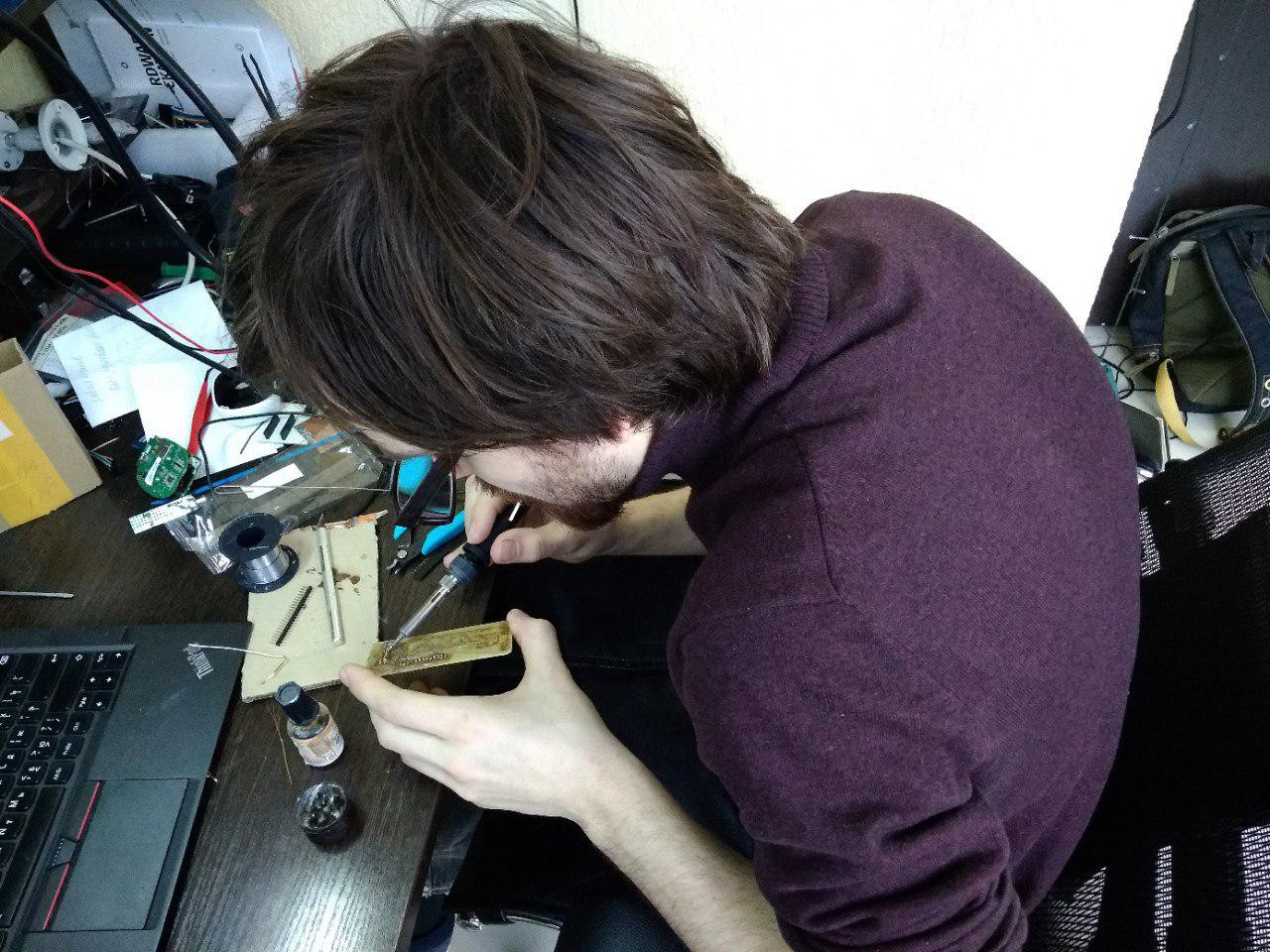
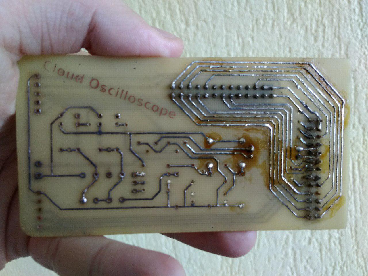
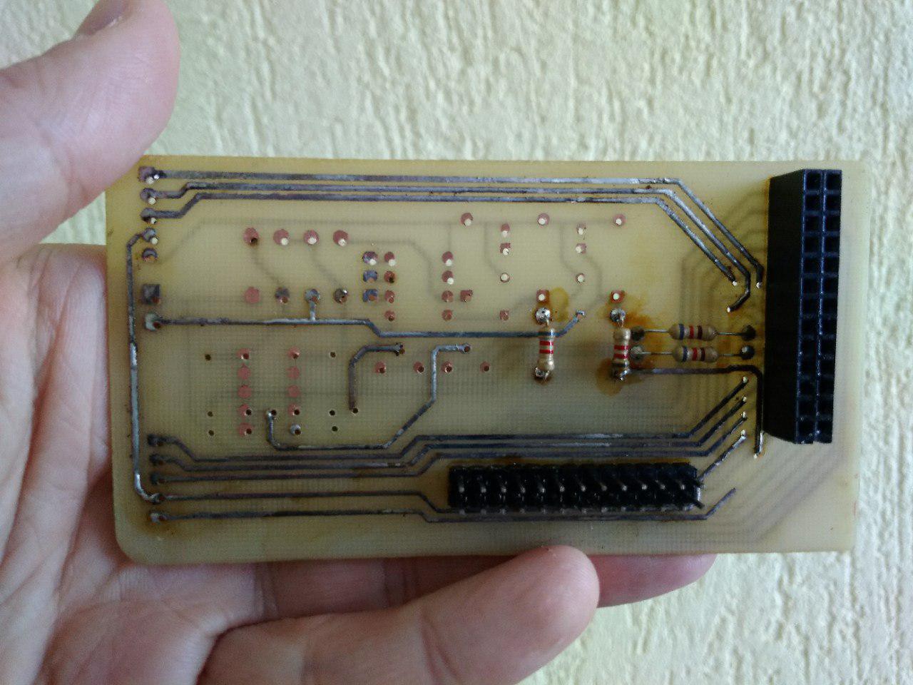
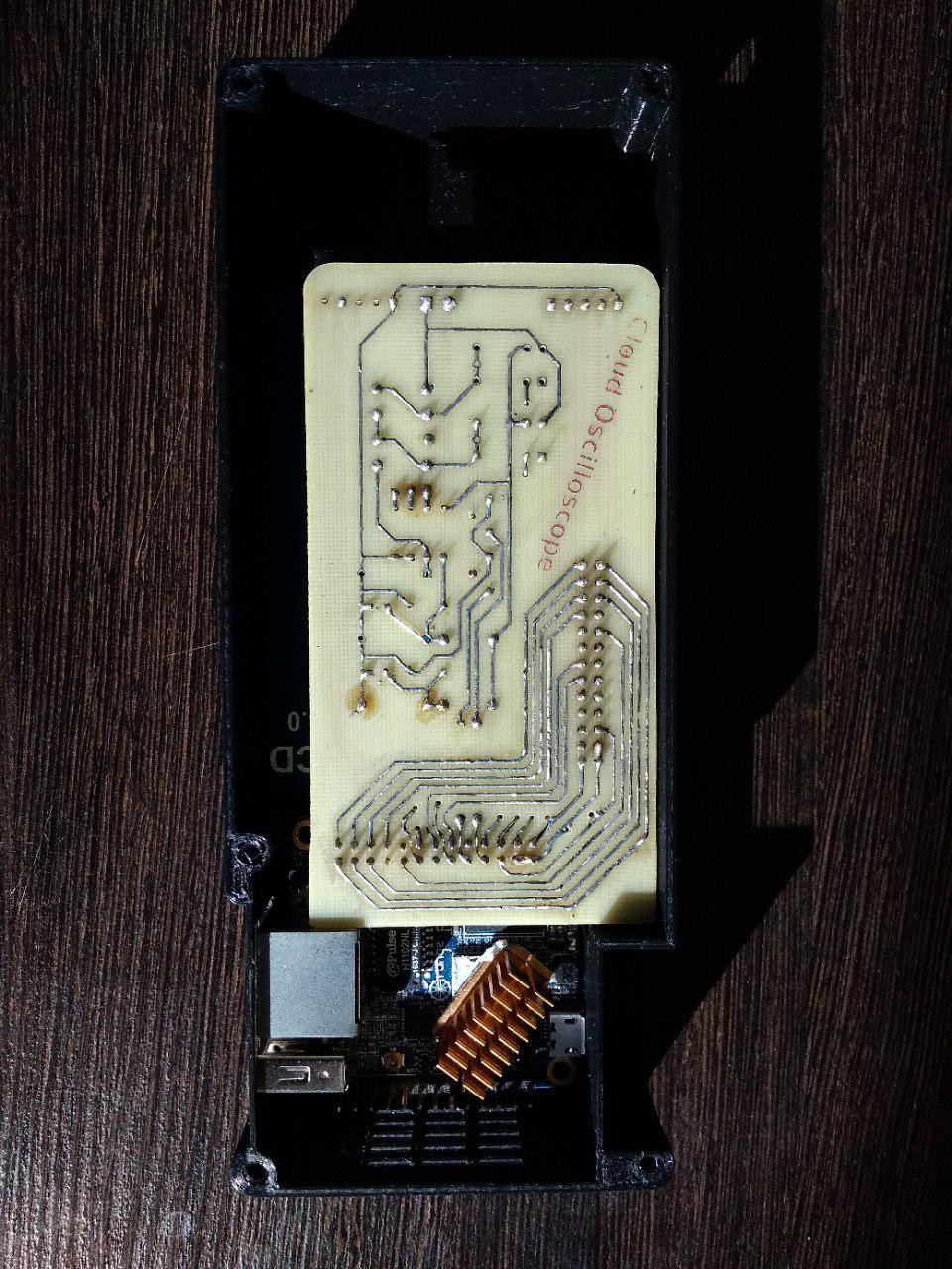
    At the build instructions you can find a PCB for printing. Andrey works on a handmade PCB with Heat transfer printing method. It is almost done and ready to include in the cloud oscilloscope. I've asked him to take the soldering iron and make a feel that he's working hard on the photo :)

  • New front case design

    Mikhail Dronov04/03/2018 at 12:18 0 comments

    Hello! 

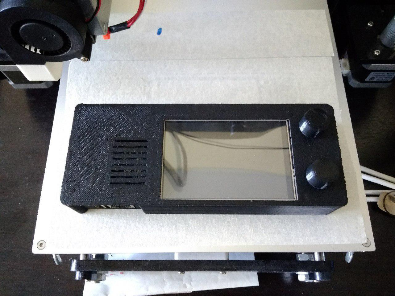
    We're working on a new version of case for our Cloud Oscilloscope. We've just printed the brand new front case, this is how it looks like.

    What do you think?

View all 2 project logs

  • 1
    Build an ADC-shield

    Use this scheme:

    Components for ADC-shield:

    • U1-mcp3201, dip-8
    • P1 - BNC connector
    • P2, P3 - TRG5-5VDC relay
    • P4, P5-connector 2.54 mm pitch 13*2 pins
    • P6, P7-connector 2.54 mm pitch 5 pins
    • P8 - connector 2.54 mm pitch 3 pins
    • Q1, Q2 - NPN 2n5551 — 2
    • R1, R8-4.7 k, 0.25 W
    • R2-5M, 0.25 W
    • R3-4M, 0.25 W
    • R4-1M, 0.25 W
    • R5, R7-820, 0.25 W
    • R6-100, 0.25 W
    • D1-zener diode 2,4 v
    • D2, D3-zener diode 4.7 v
    • C1, C4 - 47µF
    • C2, C3 - 0.1 µF
    • ec11 encoder for arduino x2

    If the output of the button on the Board is not pulled up (pull up) resistor, you need to add a 10 kOm resistor:

  • 2
    Connect SPI display to Orange Pi Zero GPIO
  • 3
    Download Armbian with legacy kernel for Orange Pi Zero and make loadable sdcard

View all 9 instructions

Enjoy this project?

Share

Discussions

Similar Projects

Does this project spark your interest?

Become a member to follow this project and never miss any updates