 Bill Peterson
I've had a Rock Band keytar controller on the shelf in my dungeon for a while that I found for a few bucks at a furniture outlet of all places. For some reason, it puts out regular MIDI in addition to being a game controller - just connect a cord from the 5-pin DIN plug to your favorite sound module, synth, or computer and rock out. I like the feel of the keybed, and it's got octave and program change buttons, and the touch slider does pitch bend and modulation (though it's a bit wonky). It communicates wirelessly with a Wii, but that's only as a game controller. I have a couple XBees from when I followed Lady Ada's very good MidiBee tutorial back when I started all this soldering nonsense in earnest. I decided to crack open the controller and stick an XBee inside, and put the other into a quick and dirty USB MIDI interface made out of a hacked cheap USB MIDI cable and give myself a wireless MIDI keytar controller to rock out on.
0%
0%
BeeTar - Wireless Rock Band Keytar
A built-in wireless MIDI-to-USB interface for Rock Band keytar using XBee radios
Become a Hackaday.io member
Already have an account? Log in.
Just one more thing
To make the experience fit your profile, pick a username and tell us what interests you.
Pick an awesome username
hackaday.io/
Your profile's URL: hackaday.io/username. Max 25 alphanumeric characters.
Pick a few interests
Projects that share your interests
People that share your interests


 You can see which lines are +3.3V (VDD1) and GND by reading the silkscreen (see image). Use a razor/knife to slice about a 6cm length of these two free of the plastic ribbon joining the five wires running to the touch sensor PCB. Then snip them in the middle and strip the free ends. Slip a bit of heat shrink onto one of the wires, then solder a new wire to each pair of wires you cut. Slide the heat shrink over the bare wires and shrink it down to keep things from shorting.
 Now for the MIDI port. Solder a couple of long wires to pins 4 and 5 (the pins on either side of the middle pin, see image). The wires should be long enough to reach around the top of the keybed and down to where the XBee/MIDI IN circuit is going to sit, just next to the touch sensor. I recommend lots of solder and a hot iron to get a good bond, and then securing the two wires to the PCB just behind the port with a bit of electrician's tape, to reduce strain on the solder joints and keep them from popping free.
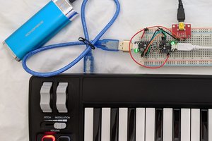
 Whack together the circuit shown in the schematic on your perfboard. I always have a crazy difficult time keeping the pins on MIDI ports straight, since they depend on whether you're looking at the front or back of the port, and the things are freaking symmetrical. Refer to the helpfully numbered image if you share my issues.
 I found that my XBee/MIDI IN circuit fit nice and snugly in its spot, and when I tucked the wires in and closed up the case I couldn't get it to rattle by shaking, so I decided friction fitting was fine and to not potentially mess things up permanently by hot gluing the circuit into place or trying to secure it some other way. Results might vary depending on what shape your little circuit ends up being, so test and use your judgement. Once you're satisfied with how your circuit fits in place, close up the controller and replace all the screws.
 gdsports
 houtson
 Andrey Kramer