Close
0%
0%

AR Workbench

Projector-camera augmented reality electronics workbench

Similar projects worth following
Projector-camera augmented reality (AR) systems make very natural and intuitive computer interfaces. This project combines an overhead camera and projector to add UI elements directly on the electronics workbench, providing virtual instruments and data augmentation in a natural and easily accessible way.

I have an idea for an augmented reality (AR) electronics workbench system.  I intend to combine an overhead camera and projector with some computer-connected instrumentation and software to make a versatile system for building and debugging hardware projects.

Most people's first experience with AR is with camera-only systems which generate augmented images, perhaps on a smartphone.  In contrast to these systems, projector-camera systems project the augmentation back into the "real world".  Although the hardware cost for a projector-camera system is larger, they can produce much more intuitive and useful augmentation.

The block diagram for the system I have in mind is shown here:
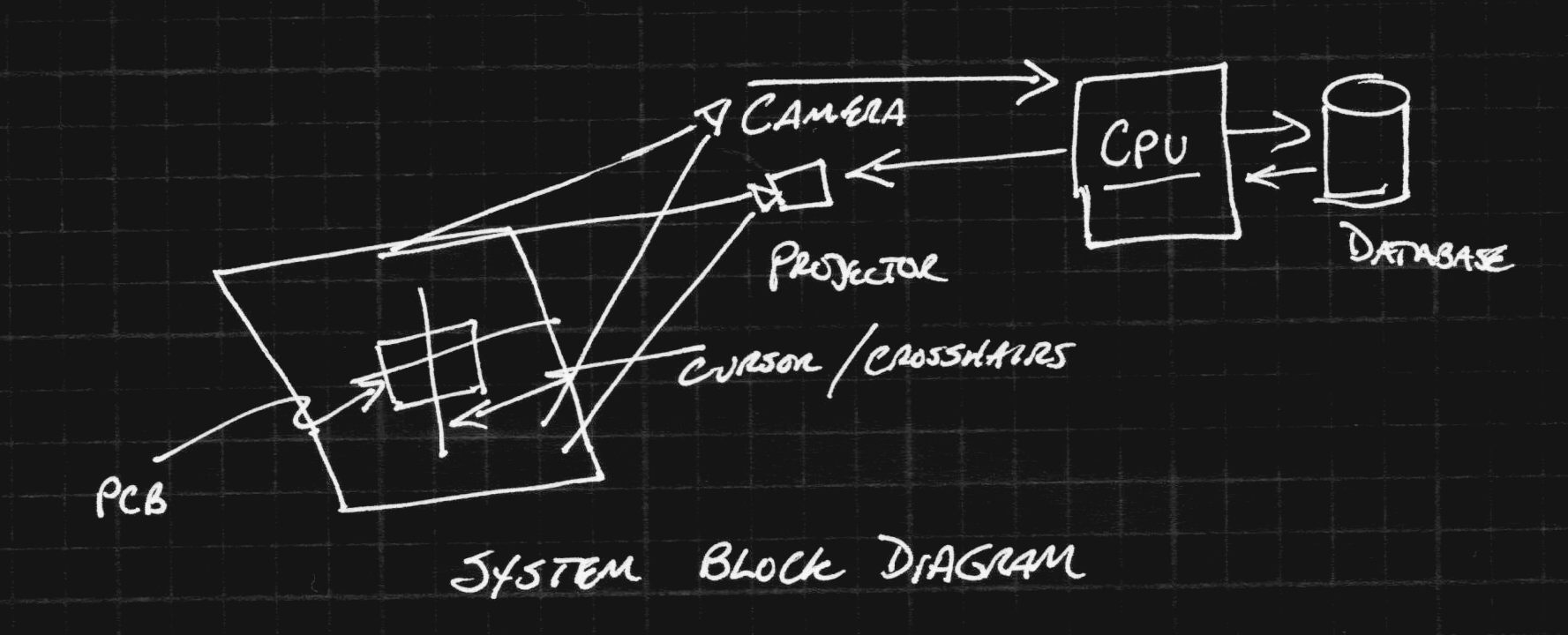
In this system, a camera is positioned over a section of a standard workbench.  Images captured by the camera are processed on a common CPU (maybe on a Raspberry Pi) to detect objects on the workbench.  Output from the system is projected back on to the workbench with a projector mounted overhead.  Once the camera and projector system are calibrated, a mapping from camera image pixels to projector image pixels can bes established.  Then, objects detected by the camera can be augmented with information projected on them.  For example, the projected data could help locate parts position for manually populating an SMD PCB. This ans several other modes are discussed in more detail below.

Goals

The design goals for this system include several modes.  These are what I've thought of so far.  If you can think of other interesting modes, please let me know.

Interactive Benchtop Instruments

In this mode, virtual displays from DMMs, oscilloscopes, logic analyzers, and other instruments can be projected on the benchtop surface.  The camera can be used to find a clean place on the bench to project the display.  For example, when probing with a voltmeter, the reading can be projected near the probe point, and can persist after the probe is moved to measure another point.  Many instruments are communication-enabled these days, and any of them could conceivably be connected this way.

CAD-Guided Assembly

Modern PCB CAD packages (for instance Eagle or KiCAD) really streamline the creation of printed circuit board designs.  But, what happens when it's time to assemble the prototypes?  Which components go where?  This mode aims to solve that problem.  Non-projective AR has previously been applied to this problem, but I think projector-based AR is the ideal solution.  In this mode, the overhead camera finds the orientation of the PCB, possibly using some fiducial markers at the corners.  Once the PCB has been found, the projector can project a cursor or marker on the PCB showing the location and orientation of any of the components.  Think of it as a pick-and-place machine where you are the end effector.

3D Scanning

Once you have a calibrated camera and projector, a 3D scanner is just a little bit of software.  The projector can illuminate the scene with gray-coded binary structured light patterns, so that each pixel gets a unique sequence of values.  When captured by the camera, this gives a correspondence between the camera pixels and the projector pixels - solving the stereo vision correspondence problem in a robust way.  You will be able to generate point clouds from 3D objects that can then be combined into full 3D models (using external software).

Heat Map

By adding an inexpensive thermal camera to the system, a heat map could be projected directly on the PCB.  Although the color of the PCB and components may make this difficult to see, modes might be created where hot-spots could be shown, or temperatures read by simply pointing at them with a probe.

I worked on two such systems about a decade ago, one on a table-top,...

Read more »

  • Reading DigiKey Barcodes

    Ted Yapo03/26/2018 at 19:40 3 comments

    My lab is a disaster, and I'm shooting for a tech-fix instead of actually getting organized.  What I'd like to have is a barcode scanner that reads DigiKey packages and allows me to catalog and track my parts inventory.  I think this would also be a great addition to the AR workbench.  So, I started prototyping a scanner and will document it here as I develop it.

    DigiKey uses  DataMatrix 2D barcodes on their packaging.  I know they at least encode DigiKey's part number and the manufacturer's part number, plus some other information which I haven't been able to map out yet.  Either one of the part numbers would be sufficient to identify and catalog the part.  I can imagine scanning bags as they arrive, then tagging the records with a location where the parts are stored, plus a count of how many are available.  When I use a part, I scan the bag again, then enter the number used.  That's enough to track inventory.

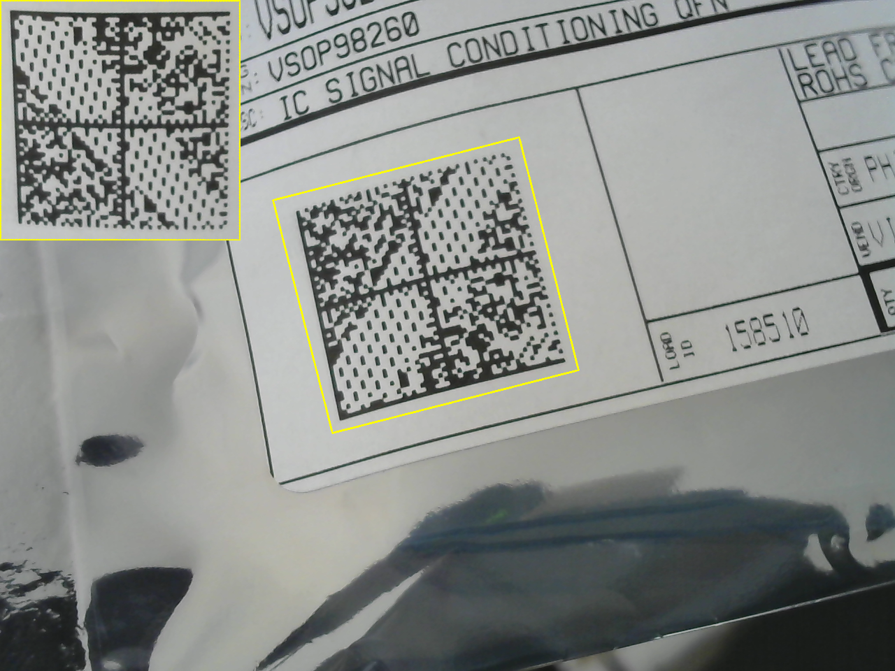
    So far, I can automatically locate the barcode in an image and crop it out, undoing some (but not all yet) perspective distortion, as shown above.  There are a handful of parameters which need fine-tuning, but the performance seems reasonable.  If it beeped when a code was successfully recognized, it would probably be usable as is.

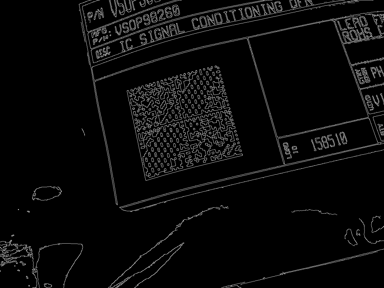
    The algorithm is really simple.  First, I convert the input image to grayscale and find edges:

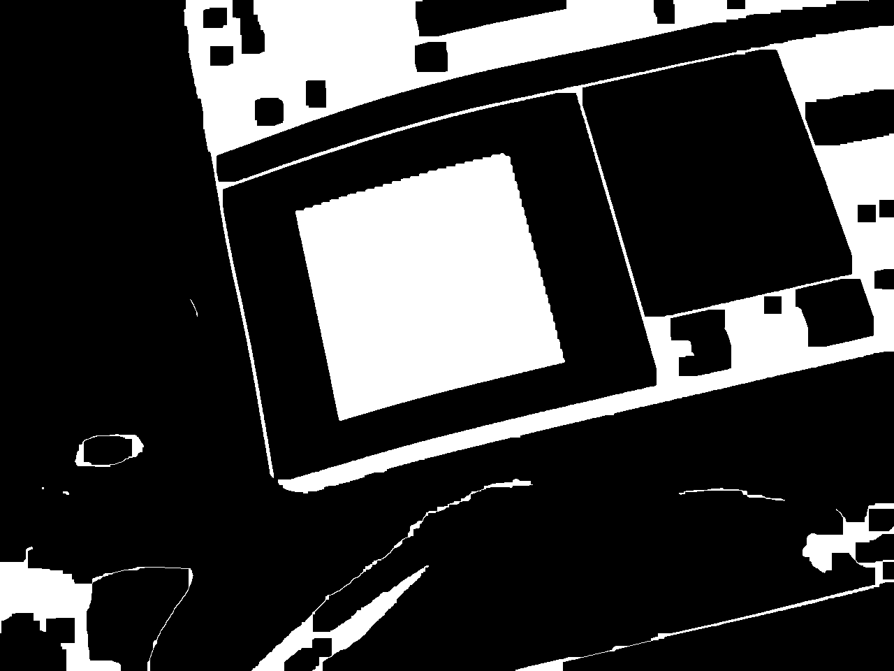
    I found this approach is suggested in a blog post about finding 1D barcodes.  The codes contain a high density of edges.  The next step is to use morphological operators to detect the codes.  I use a morphological closing (dilation followed by erosion) to connect the code into a solid mass:

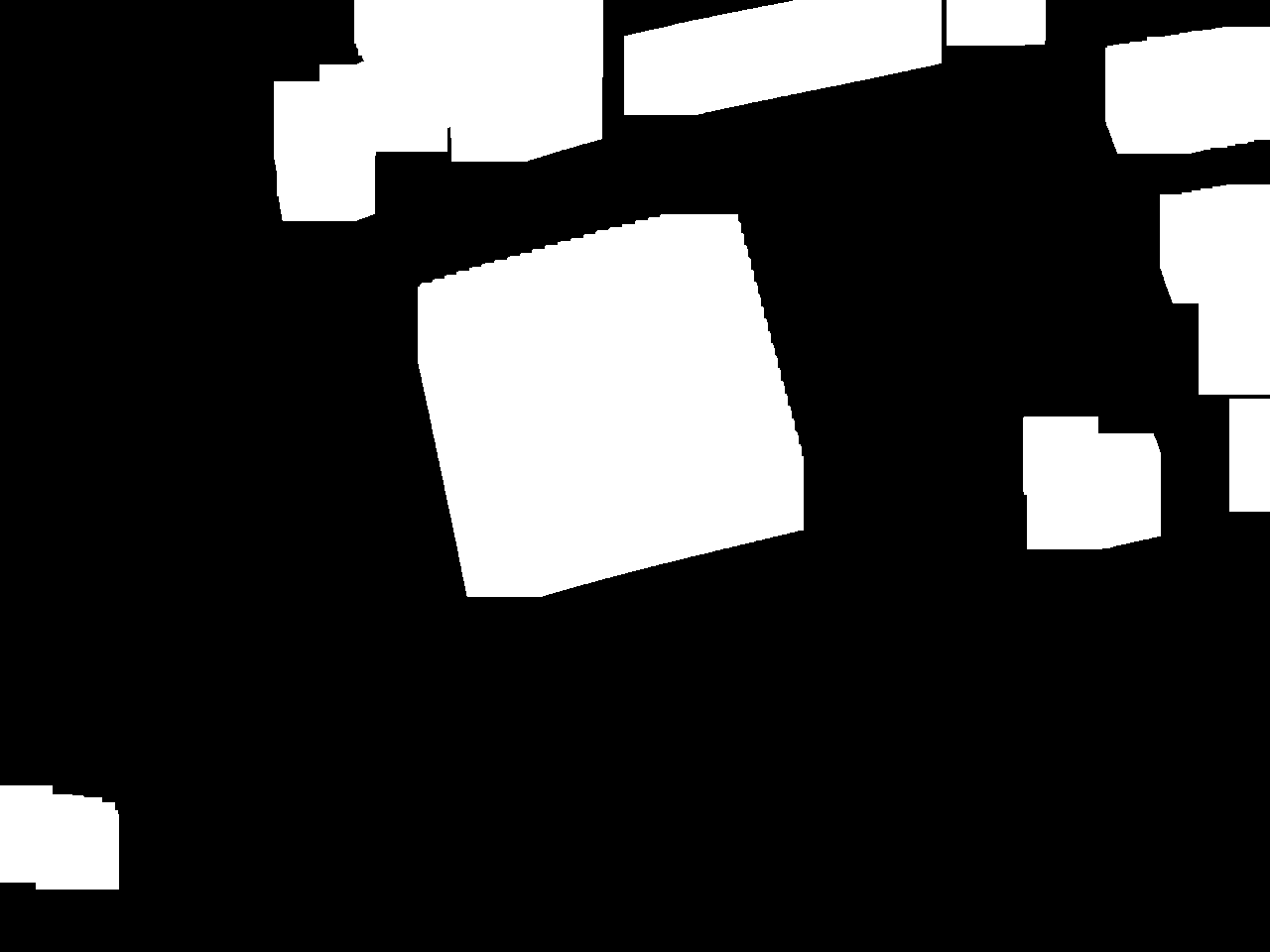
    Then use a morphological opening (erosion followed by dilation) to remove small areas:

    Finally, I apply a connected components analysis and use size-pass filtering to detect the barcode.  I use the OpenCV function minAreaRect() to find the minimum area rectangle enclosing the region, then calculate a perspective transform to warp this rectangle into a canonical square.  In general, the image of the bar code is not a rectangle, but simply a quadrilateral, so this approach does not remove all perspective distortion (you can see this in the processed image above).  It's a start, though, and I can refine it as I go.

    So far, there are a few issues.  The extracted image can currently be in one of four orientations.  I need to write some code to figure this out; I think the wide empty stripe in the code probably creates a preferred orientation if you do principal components analysis, for example.  Or, maybe a line detector could find the outer edges easily.

    I think a second round of processing on the extracted image chip to fix remaining distortions would also be helpful in recognition.  Removing the lens distortion from the camera would also help a great deal.

    I'll update this log as I go.

    Update: libdmtx

    I found the libdmtx library for decoding the barcodes.  It compiled fine, and I got a first pass at decoding going combined with my OpenCV code.  So far the end-to-end system is a little finicky, but I did get it to read and decode the barcodes at least sometimes.  So far, I get:

    [)>06PVSOP98260CT-ND1PVSOP98260K1K5415234510K6195019511K14LQ1011ZPICK12Z350468613Z15851020Z000000000000000000000000000000000000000000000000000000000000000000000000000000000000000000000000000000000000000000000000000000000000000000000000000000000000000000000000000000000000000000

     "VSOP98260CT-ND" is the DigiKey part number.

    "VSOP98260" is the manufacturer part number.

    "54152345" is the sales order number.

    "61950195" is the invoice number.

    "Q10" indicates quantity 10.

    "158150" is the "load ID" also printed on the label.  Purpose unknown.

    The...

    Read more »

  • Mockups (aka faking it)

    Ted Yapo03/21/2018 at 21:12 0 comments

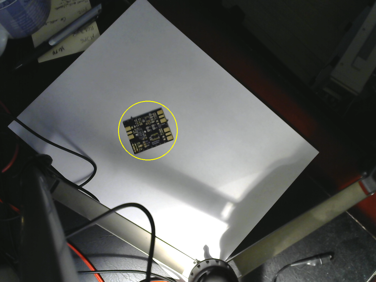
    I found some time to mock up the camera side and the projector side today.  I didn't do any calibration for either of these tests - I just wanted to get something done.  On the vision side, I can find a PCB fairly reliably on a whitish background, which I think is a reasonable requirement for the you-pick-and-place mode:

    I used thresholding in HSV color space followed by morphological dilation, connected components analysis  and then size-pass filtering.  This will be easier once I include a model of the PCB - the idea is that you can use the gerber files (and some other data extracted from the CAD program) to more easily find and orient the PCB in the frame.

    There are two issues unresolved.  First, the resolution of this camera isn't great.  I'm going to consider using a Raspberry Pi camera, which will also allow me to select a different focal length lens.  Second, I still need to find a robust solution for finding the PCB's orientation.  I have several ideas,  but it will take some time to implement them.  I'm wary of keypoint-based approaches, since the PCB's appearance changes as you populate the components.

    Projection

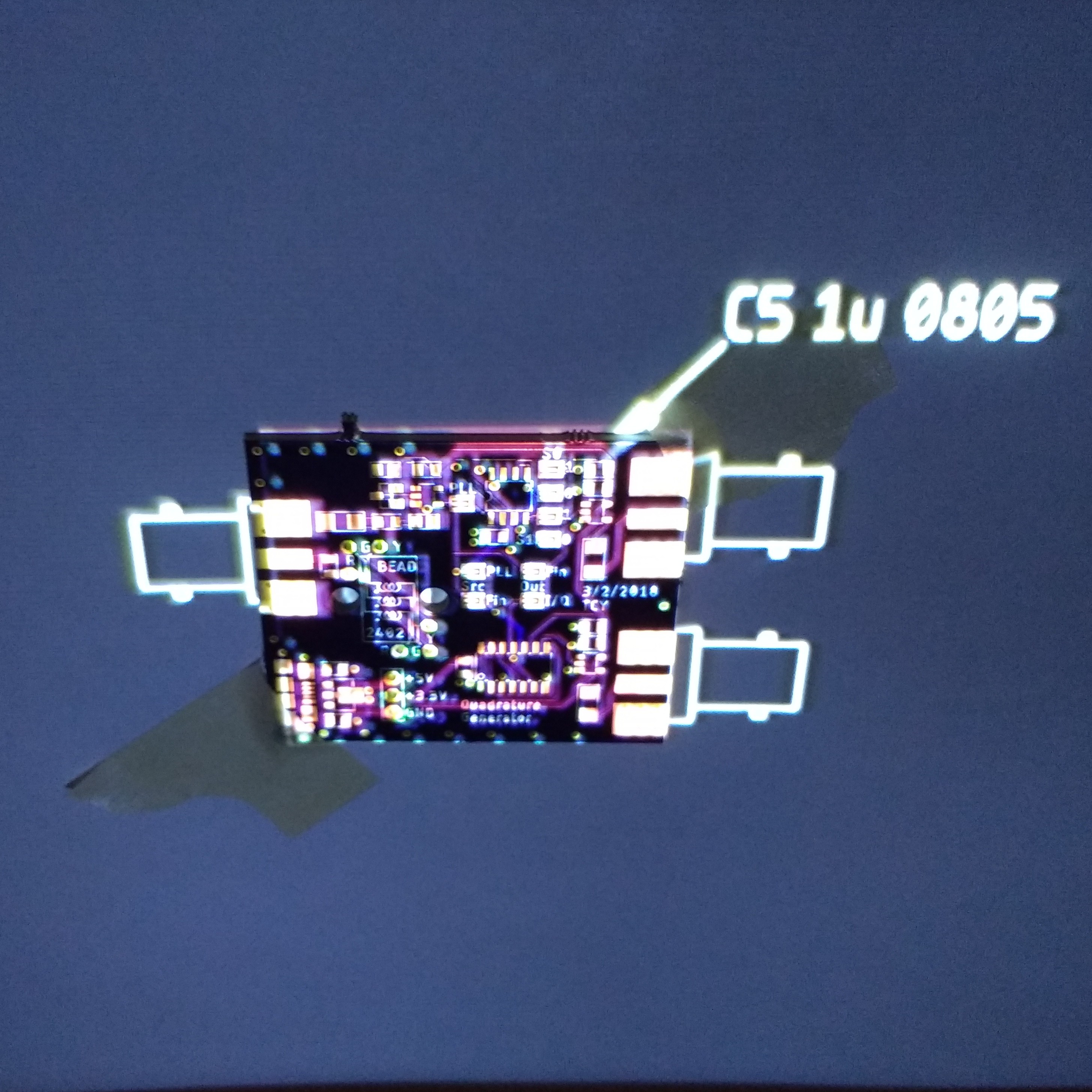
    I also tested the projection side with a mocked-up program.  The image was exported from Eagle as a test, and the PCB was very roughly aligned to show how it will work.  In this case, it is showing the location of C5.

    The PCB is actually taped to the back of a door in this image, since I don't have a frame for downward-projection yet.  You can see the image and the PCB aren't very well aligned.  Once the projector has been corrected for radial distortion and geometrically calibrated, this will look much better.  It probably doesn't make much sense to project all of the information shown here; just the current part and some registration marks to ensure the PCB was detected correctly.

    There are also errors in the image because the PCB surface is not at the same depth as the background.  This can be corrected by using a 3D model for the PCB and texture mapping the image on it before projection.  Once the camera and projector are calibrated and registered into the same 3D coordinate frame, this kind of projection is straightforward.

    I am thinking I need more resolution on the projector, though.  The 800x480 might work for a smaller bench area, but for a full workspace, a HD projector (or several lower-res ones) would be helpful.

    3D Scanning

    I also realized that once the camera and projector are calibrated, the system can be used as (fast!) 3D scanner by projection of structured light patterns.  I wrote code to do this years ago, but see now that a similar gray-code binary structured light pattern generator is included in OpenCV.  Using this, it should be easy to add 3D scanning to the system.

    Next Up

    Calibration

  • Initial Design Thoughts

    Ted Yapo03/17/2018 at 13:53 0 comments

    I started wondering how much this was going to cost me, and decided to try to build it with what I already have - at least for a first prototype.  If funding should somehow magically appear, I can consider the ideal components.  Admittedly, my junk pile may be larger than most, but I think it's a good exercise to keep the costs down at first.  In this log, I'm going to consider the following:

    • Projector selection
    • Camera selection
    • Computer selection
    • Thermal imager selection
    • Vision Libraries
    • Voice recognition
    • Speech synthesis
    • Instrumentation Interface
    • Licensing

    I think you could probably put together a minimal system for $200 if you had to buy everything.

    I have some initial ideas about the computer vision algorithms, but I'll write those up in a separate log.

    Projector Selection

    The projector is really the limiting factor in this system.  High-resolution projectors are expensive.

    I have two projectors that I can try.  One is the standard office type with incandescent bulb and a 1024x768 resolution.  It's very old and represents a previous technology.  More interesting is one I bought recently for about $80. 

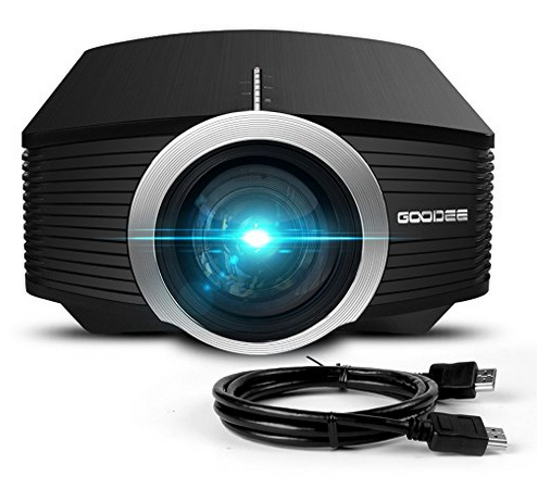
    You can check it out at Amazon here. The resolution is only 800x480, which seems to be very common in inexpensive LED projectors.  There are many variations on these on the market - and almost all of them say "1080p", which simply means they'll accept a 1080p signal and down-sample to 800x480 for display.  The price of this class of projectors seems to range from around $55 on the low end up to maybe $120, with no solid way to tell what you're getting as far as I can tell.  They're all over-hyped and up-spec'd, but at least they seem to work.

    What limitations does the 800x480 resolution imply?  If you want 1mm pixels on the bench, then the bench area is limited to 80x48 cm.  This seems like a generous working area.  If instead, you want a higher resolution of 0.5mm pixels, you now get a 40x24cm bench-top  This is probably as small as you want to go, but the extra resolution might be useful for the you-pick-and-place mode.

    For other applications, this resolution is less than ideal.  In one mode, I envision projecting the display from an oscilloscope on the bench-top.  This is easier than it might sound with modern instruments.  For example, the #Driverless Rigol DS1054Z screen capture over LAN  project shows how you can capture screenshots from the Rigol DS1054Z scope through the LAN port.  These could easily be captured and displayed on the desktop, probably with a decent update rate.  Unfortunately, the DS1054Z has an 800x480 screen, which would use the entire bench-top with this projector.  You might reduce the size of the image - maybe 1/2 scale would still be readable, or capture the waveforms instead of a screenshot and draw them in a smaller area.  I will have to experiment with this a bit.

    There is an issue with any consumer projector, though. They are designed for larger images, so they won't focus up close and produce images with 1mm (or smaller) pixels.  I can think of two solutions - either open the projector and modify it for closer focus, or add an external lens.  I've modified the focus range on camera lenses before, and I really don't enjoy it, so the external lens it is.

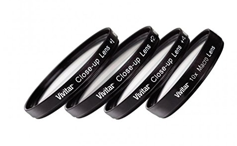
    At one point, I bought a cheap ($8) set of "close-up" filters for a 50mm SLR lens like these:

    They let you do macro photography with your normal lens.  They're not color corrected or even anti-reflection coated, so the image quality is less than spectacular, but they let you focus on close objects. Since projectors are just cameras in reverse, the lenses will let...

    Read more »

View all 3 project logs

Enjoy this project?

Share

Discussions

Dimitris Zervas wrote 07/27/2018 at 11:53 point

Dude that's amazing. Could help a lot to live stream as well! Keep it up!

  Are you sure? yes | no

anfractuosity wrote 07/27/2018 at 06:01 point

Hi Ted, this is a really awesome project!  Not sure if you've seen this projector or not - Excelvan CL720D.  It may be too expensive though. But it is supposed to be native 720p.

I wonder which colour PCBs work best for projecting on to?

You could let people move around the virtual instruments with hand gestures too!

Also it would be nice to see maybe schematics / pcb layouts on the workbench too. It could then maybe have a way of visualising how the schematic component links to the place of the component on the PCB with arrows or something.

Also what framerate camera are you planning on using?

Also I'm just thinking I always lose tools on the worktop, maybe it could search for and find various tools, like you ask it to find where snippers are, and it uses visual recognition to locate and then circle their location.

Sorry if I missed this, are you planning on using OpenCV via C++ or Python, or..?

  Are you sure? yes | no

Ted Yapo wrote 07/30/2018 at 00:41 point

I hadn't seen that projector - it looks decent enough thanks for the tip!  You really can't have too much resolution - 1080P would be great, with 4k ideal, but I can't afford that.

I have done the initial experiments in C++, since every once in a while, you find something missing from OpenCV, and I find it faster to crank out some efficient C++ than Python.

To be honest, I haven't worked on this in a while; other things got in the way, as they often do.  Somehow it got picked up on the blog, though.  It might motivate me to pick it back up again now.  Or not, who knows :-)

  Are you sure? yes | no

Minimum Effective Dose wrote 07/21/2018 at 05:34 point

I'm curious, how does a system like this keep the projector's output from "contaminating" what the camera sees?

Years ago I tried making a similar system using camera and projector but I didn't know what I was doing, and I found that I had trouble processing the images the camera saw since they also picked up what the projector was displaying, and I got a hall-of-mirrors effect.

Like I said, I didn't know what I was doing but how is that problem avoided?

  Are you sure? yes | no

Ted Yapo wrote 07/26/2018 at 01:49 point

I've done it two ways on different systems in the past - in both cases, avoiding imaging the projected display entirely.  In one system, the projector was switched off to take the images.  Depending on your setup, this could be as short as a single dropped video frame (if you have a decent machine-vision camera with an electronic trigger input, for example).  You probably would never see it. In my case, it was many frames, and the blink was obvious.

The other system I worked on used IR markers on objects along with an IR camera.  Surprisingly, even incandescent-illuminated projectors emit negligible IR (it gets filtered out to prevent overheating of the optical system), so they don't interfere with an IR camera.  LED projectors are even better.

  Are you sure? yes | no

Minimum Effective Dose wrote 07/26/2018 at 02:17 point

I understand, thanks for the details. I guess there's no magic solution. I ended up sending a white image while the camera took a picture (and using the white flood as a "flash" so the images were consistent) but while that worked great for the camera, it was terribly unusable from the user's point of view -- the projector regularly flashing white was jarring to say the least!

  Are you sure? yes | no

jaromir.sukuba wrote 03/16/2018 at 20:32 point

"The camera can be used to find a clean place on the bench to project the display."

Apparently, I'm out of luck with my bench.

  Are you sure? yes | no

Ted Yapo wrote 03/16/2018 at 21:02 point

"The adapted windshield wiper can be used to create a clean place on your bench"

  Are you sure? yes | no

Similar Projects

Does this project spark your interest?

Become a member to follow this project and never miss any updates