Ted Yapo
-
Reading DigiKey Barcodes
03/26/2018 at 19:40 • 3 commentsMy lab is a disaster, and I'm shooting for a tech-fix instead of actually getting organized. What I'd like to have is a barcode scanner that reads DigiKey packages and allows me to catalog and track my parts inventory. I think this would also be a great addition to the AR workbench. So, I started prototyping a scanner and will document it here as I develop it.
![]()
DigiKey uses DataMatrix 2D barcodes on their packaging. I know they at least encode DigiKey's part number and the manufacturer's part number, plus some other information which I haven't been able to map out yet. Either one of the part numbers would be sufficient to identify and catalog the part. I can imagine scanning bags as they arrive, then tagging the records with a location where the parts are stored, plus a count of how many are available. When I use a part, I scan the bag again, then enter the number used. That's enough to track inventory.
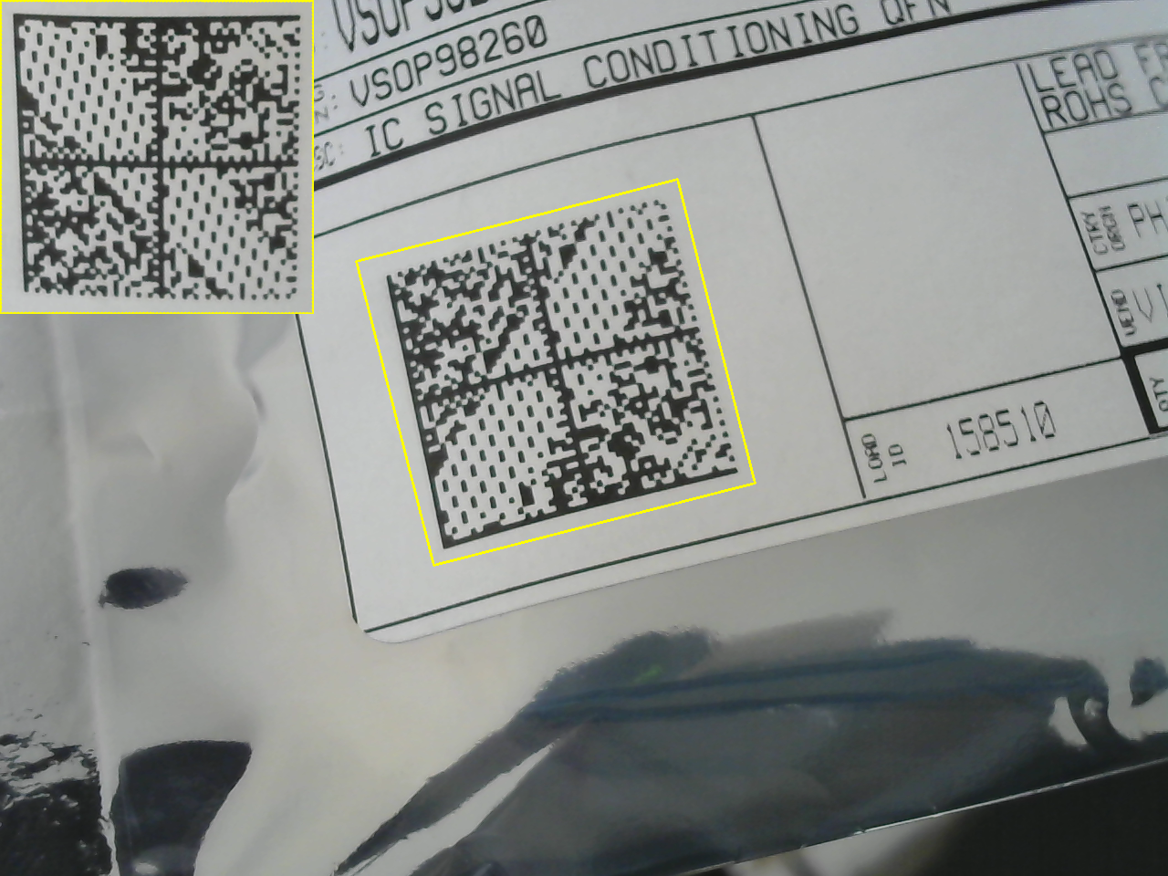
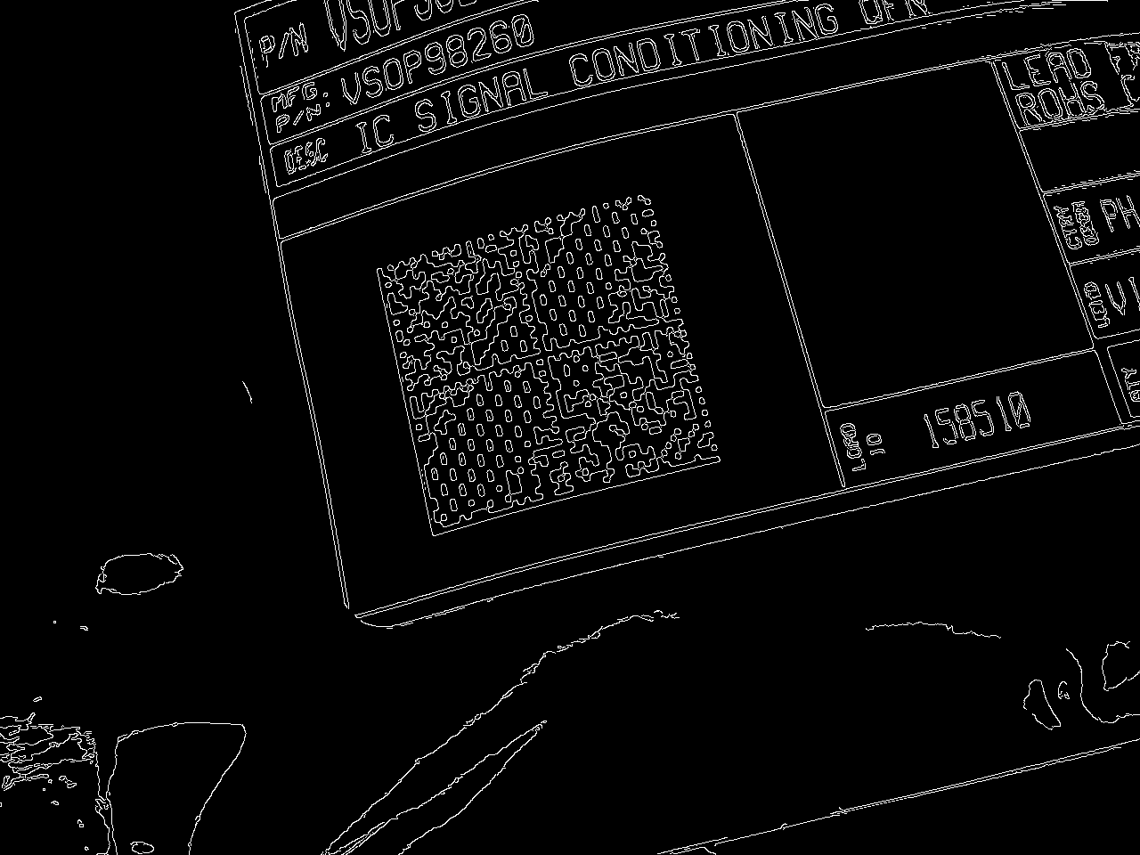
So far, I can automatically locate the barcode in an image and crop it out, undoing some (but not all yet) perspective distortion, as shown above. There are a handful of parameters which need fine-tuning, but the performance seems reasonable. If it beeped when a code was successfully recognized, it would probably be usable as is.The algorithm is really simple. First, I convert the input image to grayscale and find edges:
![]()
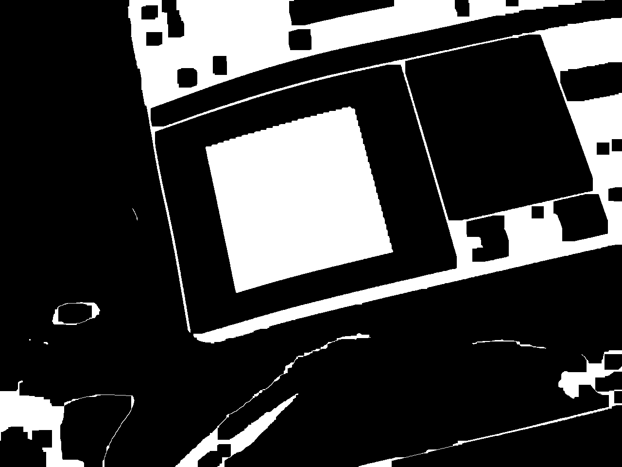
I found this approach is suggested in a blog post about finding 1D barcodes. The codes contain a high density of edges. The next step is to use morphological operators to detect the codes. I use a morphological closing (dilation followed by erosion) to connect the code into a solid mass:
![]()
Then use a morphological opening (erosion followed by dilation) to remove small areas:
![]()
Finally, I apply a connected components analysis and use size-pass filtering to detect the barcode. I use the OpenCV function minAreaRect() to find the minimum area rectangle enclosing the region, then calculate a perspective transform to warp this rectangle into a canonical square. In general, the image of the bar code is not a rectangle, but simply a quadrilateral, so this approach does not remove all perspective distortion (you can see this in the processed image above). It's a start, though, and I can refine it as I go.
So far, there are a few issues. The extracted image can currently be in one of four orientations. I need to write some code to figure this out; I think the wide empty stripe in the code probably creates a preferred orientation if you do principal components analysis, for example. Or, maybe a line detector could find the outer edges easily.
I think a second round of processing on the extracted image chip to fix remaining distortions would also be helpful in recognition. Removing the lens distortion from the camera would also help a great deal.
I'll update this log as I go.
Update: libdmtx
I found the libdmtx library for decoding the barcodes. It compiled fine, and I got a first pass at decoding going combined with my OpenCV code. So far the end-to-end system is a little finicky, but I did get it to read and decode the barcodes at least sometimes. So far, I get:
[)> 06 PVSOP98260CT-ND 1PVSOP98260 K 1K54152345 10K61950195 11K1 4L Q10 11ZPICK 12Z3504686 13Z158510 20Z000000000000000000000000000000000000000000000000000000000000000000000000000000000000000000000000000000000000000000000000000000000000000000000000000000000000000000000000000000000000000000"VSOP98260CT-ND" is the DigiKey part number.
"VSOP98260" is the manufacturer part number.
"54152345" is the sales order number.
"61950195" is the invoice number.
"Q10" indicates quantity 10.
"158150" is the "load ID" also printed on the label. Purpose unknown.
The other fields are a mystery so far.
Update: Perspective Correction
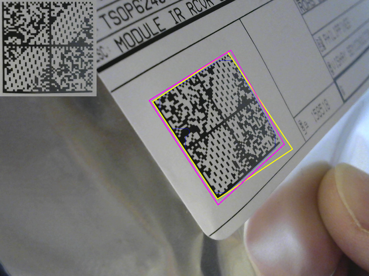
I had to write a bunch of code for this, but it seems to work pretty well. There isn't a RANSAC line-finder in OpenCV for some reason, so I had to make one. It works by randomly selecting two points from a noisy set (containing some lines), then accepting points close to the line connecting the two chosen points. The line is then least-squares fit to the set of selected (inlier) points. I use this to find a quadrilateral region enclosing the barcode. Mapping this quadrilateral to a square with a planar homography removes the perspective distortion. You can see it here, where the enclosing rectangle (yellow) really doesn't capture the shape of the code, while the fit lines (magenta) do.
![]()
The image chip in the top left is the extracted and corrected barcode. There's still some distortion caused by the code not being flat, but that's probably best handled after the chip has been extracted. I'm thinking of ways to deal with this.
So far, the experiments with libdmtx have been mixed. It seems *very* slow, and doesn't recognize the codes very often at all.
I think the vision code is getting good enough that I can take a crack at interpreting the barcode myself. I found this document which explains much of the code. If I limit myself to the DigiKey version (size, shape, etc), I can probably write a decently robust algorithm.
Next Steps
I need to clean this prototype code up, refine it a bit, and put it up on the githubs.
Digikey has a published API and client (C#, anyway). You have to register with them to use it, but this might be the easiest way to collect information about each part as it is scanned.
Alternatively, the data could be scraped from the DigiKey web site, although that sounds like a pain. And it could be fragile.
-
Mockups (aka faking it)
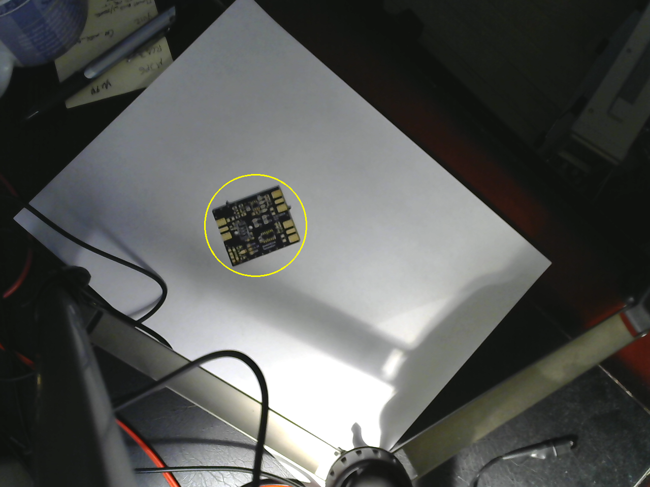
03/21/2018 at 21:12 • 0 commentsI found some time to mock up the camera side and the projector side today. I didn't do any calibration for either of these tests - I just wanted to get something done. On the vision side, I can find a PCB fairly reliably on a whitish background, which I think is a reasonable requirement for the you-pick-and-place mode:
![]()
I used thresholding in HSV color space followed by morphological dilation, connected components analysis and then size-pass filtering. This will be easier once I include a model of the PCB - the idea is that you can use the gerber files (and some other data extracted from the CAD program) to more easily find and orient the PCB in the frame.
There are two issues unresolved. First, the resolution of this camera isn't great. I'm going to consider using a Raspberry Pi camera, which will also allow me to select a different focal length lens. Second, I still need to find a robust solution for finding the PCB's orientation. I have several ideas, but it will take some time to implement them. I'm wary of keypoint-based approaches, since the PCB's appearance changes as you populate the components.
Projection
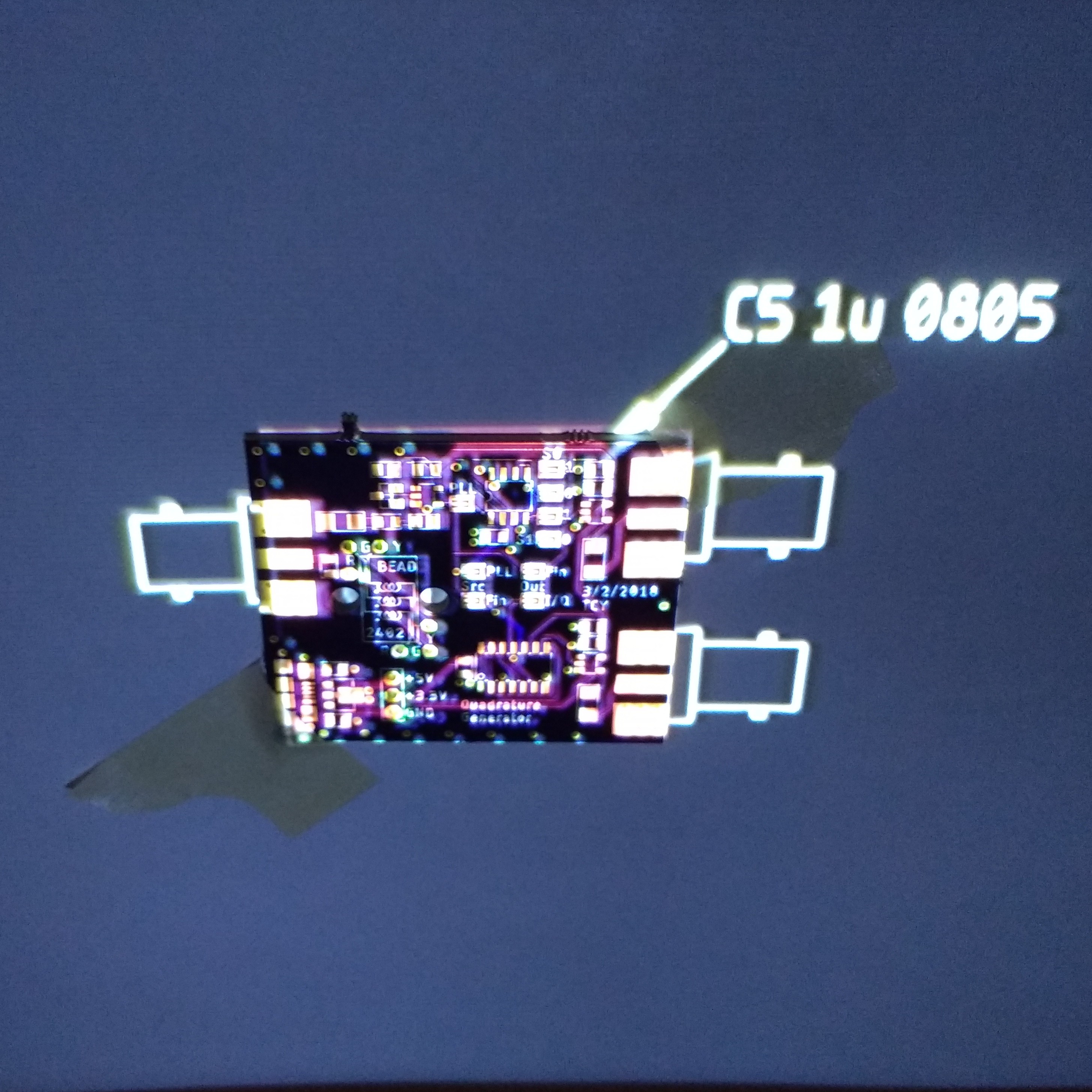
I also tested the projection side with a mocked-up program. The image was exported from Eagle as a test, and the PCB was very roughly aligned to show how it will work. In this case, it is showing the location of C5.
![]()
The PCB is actually taped to the back of a door in this image, since I don't have a frame for downward-projection yet. You can see the image and the PCB aren't very well aligned. Once the projector has been corrected for radial distortion and geometrically calibrated, this will look much better. It probably doesn't make much sense to project all of the information shown here; just the current part and some registration marks to ensure the PCB was detected correctly.
There are also errors in the image because the PCB surface is not at the same depth as the background. This can be corrected by using a 3D model for the PCB and texture mapping the image on it before projection. Once the camera and projector are calibrated and registered into the same 3D coordinate frame, this kind of projection is straightforward.
I am thinking I need more resolution on the projector, though. The 800x480 might work for a smaller bench area, but for a full workspace, a HD projector (or several lower-res ones) would be helpful.
3D Scanning
I also realized that once the camera and projector are calibrated, the system can be used as (fast!) 3D scanner by projection of structured light patterns. I wrote code to do this years ago, but see now that a similar gray-code binary structured light pattern generator is included in OpenCV. Using this, it should be easy to add 3D scanning to the system.
Next Up
Calibration
-
Initial Design Thoughts
03/17/2018 at 13:53 • 0 commentsI started wondering how much this was going to cost me, and decided to try to build it with what I already have - at least for a first prototype. If funding should somehow magically appear, I can consider the ideal components. Admittedly, my junk pile may be larger than most, but I think it's a good exercise to keep the costs down at first. In this log, I'm going to consider the following:
- Projector selection
- Camera selection
- Computer selection
- Thermal imager selection
- Vision Libraries
- Voice recognition
- Speech synthesis
- Instrumentation Interface
- Licensing
I think you could probably put together a minimal system for $200 if you had to buy everything.
I have some initial ideas about the computer vision algorithms, but I'll write those up in a separate log.
Projector Selection
The projector is really the limiting factor in this system. High-resolution projectors are expensive.
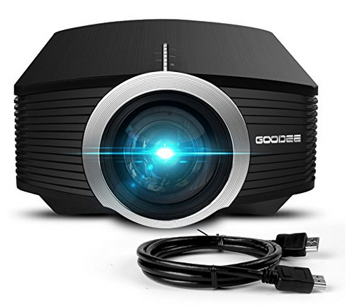
I have two projectors that I can try. One is the standard office type with incandescent bulb and a 1024x768 resolution. It's very old and represents a previous technology. More interesting is one I bought recently for about $80.
![]()
You can check it out at Amazon here. The resolution is only 800x480, which seems to be very common in inexpensive LED projectors. There are many variations on these on the market - and almost all of them say "1080p", which simply means they'll accept a 1080p signal and down-sample to 800x480 for display. The price of this class of projectors seems to range from around $55 on the low end up to maybe $120, with no solid way to tell what you're getting as far as I can tell. They're all over-hyped and up-spec'd, but at least they seem to work.
What limitations does the 800x480 resolution imply? If you want 1mm pixels on the bench, then the bench area is limited to 80x48 cm. This seems like a generous working area. If instead, you want a higher resolution of 0.5mm pixels, you now get a 40x24cm bench-top This is probably as small as you want to go, but the extra resolution might be useful for the you-pick-and-place mode.
For other applications, this resolution is less than ideal. In one mode, I envision projecting the display from an oscilloscope on the bench-top. This is easier than it might sound with modern instruments. For example, the #Driverless Rigol DS1054Z screen capture over LAN project shows how you can capture screenshots from the Rigol DS1054Z scope through the LAN port. These could easily be captured and displayed on the desktop, probably with a decent update rate. Unfortunately, the DS1054Z has an 800x480 screen, which would use the entire bench-top with this projector. You might reduce the size of the image - maybe 1/2 scale would still be readable, or capture the waveforms instead of a screenshot and draw them in a smaller area. I will have to experiment with this a bit.
There is an issue with any consumer projector, though. They are designed for larger images, so they won't focus up close and produce images with 1mm (or smaller) pixels. I can think of two solutions - either open the projector and modify it for closer focus, or add an external lens. I've modified the focus range on camera lenses before, and I really don't enjoy it, so the external lens it is.
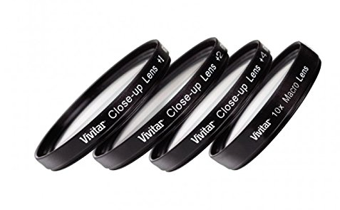
At one point, I bought a cheap ($8) set of "close-up" filters for a 50mm SLR lens like these:
![]()
They let you do macro photography with your normal lens. They're not color corrected or even anti-reflection coated, so the image quality is less than spectacular, but they let you focus on close objects. Since projectors are just cameras in reverse, the lenses will let the projector focus a closer, smaller image. I found the lens set in a box of camera junk this morning, and tried them in front of the projector lens. They work great! With the +4 lens, you can focus all the way down to an image around 20cm wide. The +1 or +2 lenses will probably be most appropriate for the prototype, depending on how high the projector is.
So, the total cost for projector and lenses : $90. I assume whatever I build or print to hold the lens in place is free.
Higher resolution projectors cost more. It looks like 720p versions can be had for $200, while 1080p costs $500 or so. I'll keep my eye out for bargains.
Camera Selection
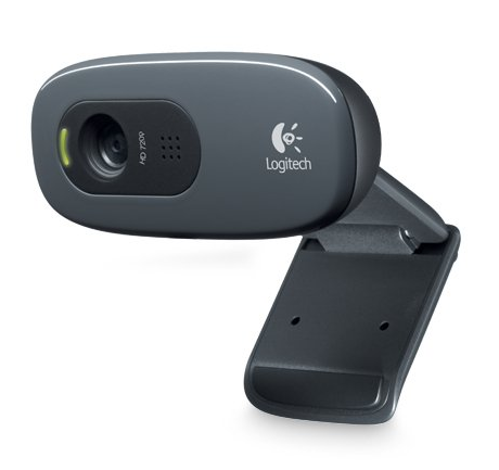
Cameras are cheap these days, but there are still a few issues. Webcams are the easiest way to go, but they're less than ideal for this system for a few reasons. First, very few (if any) webcams have interchangeable lenses these days. I'd ideally like a camera that used CS-mount lenses like found on security "box cameras," which are inexpensively available in many focal lengths. Instead, I will have to settle for whatever focal length comes on the webcam, and adjust the camera distance instead.
A second issue with modern webcams is auto-focus. At first, this sounds like a good thing. But, from a computer vision point of view, changing the focus of the lens changes the camera model. In other words, if the camera is geometrically calibrated at one focus, then the camera changes its focus, the calibration may no longer be valid. I am going to avoid auto-focus cameras for now. This unfortunately limits the resolution, because higher resolution cameras more easily show focus errors, so manufacturers are more likely to include auto-focus on higher-resolution cameras.
I happened to have two Logitech C270 cameras here for stereo vision experiments. They're $20 each, and support 1280x720 resolution at 30FPS using MJPEG compression. One of them will do for now.
![]()
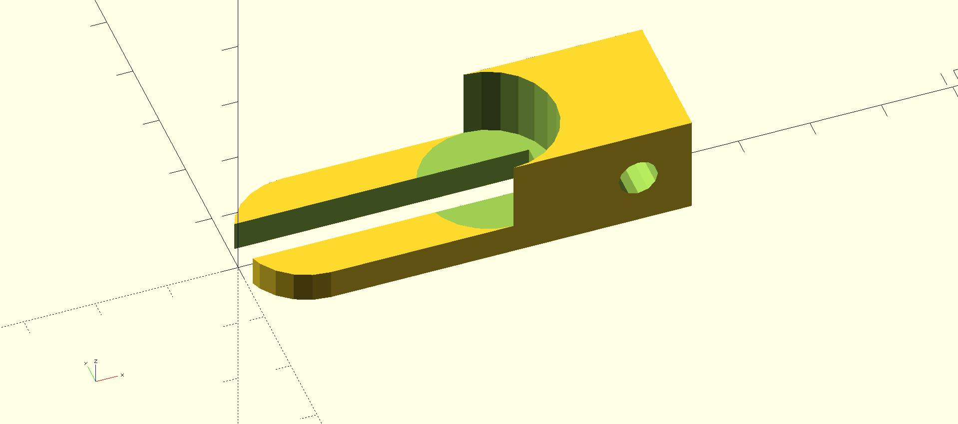
A final problem with webcams is the lack of decent mounting options. All cameras should have a 1/4"-20 standard tripod thread. Period. When I first bought these cameras, I designed this adapter that clips on to them and allows you to mount them properly:
![]()
Computer Selection
Although getting the vision algorithms to run in real-time may be a challenge, I've decided to start with a Raspberry Pi 2. It's tempting to go with the 3, but I already have the 2 here, and the 3 isn't really that much faster. Let's call it $50 with the SD card, power supply, case, and all the other crap you need to add to make it usable. I can always fall back to using a desktop, but considering what I was able to do on desktops ten years ago, the Pi will probably do.
Thermal Imager Selection
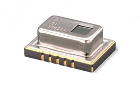
The FLIR Leptons are awesome, but could easily double the cost of this system. Instead, I'm going to start with a Panasonic Grid-EYE sensor. They run about $20, then you need a PCB to put it on. Let's call it $30.
![]()
The resolution is very low (8x8), but it should give a rough indication of the temperature distribution, and could trigger a warning if dangerous temperatures were detected.
I don't have one of these, so I'll have to shell out some cash to get one.
At some point, I can revisit the Lepton decision.
Vision Libraries
I'm going to use OpenCV as the base for the vision code. It has its quirks, but it's a decent platform to build on. Image capture is there already, as well as a lot of the low-level building blocks I'll want to use. Robust estimation of planar homographies is a single function call, for instance. No more screwing around with SVD.
Voice Recognition
I'm envisioning this system as a "heads-down" display. You shouldn't have to look away from what you are working on, except perhaps for a tool change. To facilitate this, I'm going to add voice recognition. It's 2018, and you can talk to computers, so there's no reason I shouldn't be able to add this fairly easily. I did a brief survey of the higher-level toolkits available, and the big selling points seem to be how they emulate Alexa or Siri. That's not interesting to me. The state of AI today is that limited-domain applications perform better. I found the CMUSphinx library for recognition, which a few of the higher-level packages use. I'm going to give that a try.
An example interaction might look like:
"Betty, show the oscilloscope"
"Oscilloscope displayed"
"Betty, decode RS-232"
"Showing decoded RS-232 stream"
"Betty, make me a sandwich"
"Bleep blop. You are a sandwich"
I prefer to speak with female computers. You could switch it to Bob mode if you like.
Speech Synthesis
Betty needs to talk as well as listen. I'm going to start with the CMU flite synthesis package, mostly because I've used it before. It's not great, but it's easy. I'll also be evaluating others as I find them. The demos for MaryTTS sound very nice, but I haven't tried programming with it yet.
Instrumentation Interface
Many instruments come with communication ports these days. Lower-end devices may have RS-232, USB, or LAN connectivity, while others may sport GPIB. For some devices, like the Rigol oscilloscopes and spectrum analyzers, the API over the LAN is very straightforward and well-documented, so considering the popularity of these devices, it might make sense to support them directly.
To support the widest variety of devices, it might make sense to use the Sigrok library.
Licensing
I release everything I do under a permissive license these days. This is at odds with some of the licenses of the libraries I may use, so I won't be distributing binaries. You want it, you build it.
Next Up
Planar homographies for fun and profit!