-
Bad news everyone !
02/29/2016 at 18:51 • 0 commentsSo, I started a new job and since I'm buying a new car, I got less and less time to spend on the ToxPhone. Since the Raspberry Pi Zero contest is coming to an end, I decided that I could at least throw a finished product with an unfinished software... But couldn't achieve that...
First I painted the ToxPhone in red as planned and added some layers of varnish. Unfortunately, my garage is a dusty place and I got dog's hairs stucked in the paint. It looks good anyway and the screen fitted perfectly along with the original board. The problem came with the Raspberry Pi. I couldn't fit it at all so I have to admit that my project isn't ready for the contest. It's too pricey to get a Raspberry Pi Zero and the other solution would be to skip the vintage phone and start a new one from the ground with a beautiful box, a nice keyboard and everything it needs more easily. But this breaks the concept of repurposing old phones.
Also, a part broke inside so I can't use the phone switch anymore.
The project is now stalled. I hope you enjoyed anyway. I will try to publish the clean, finished and incomplete code and give my help to anyone who will try to replicate it.
-
Finally an update
02/08/2016 at 18:43 • 0 commentsOk so it's been one week and not a lot of update so I'll try to catch up and list all of the changes since last week.
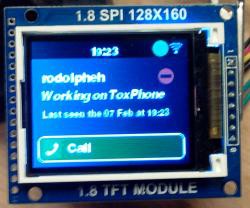
First, I told that we had a working example for an UI. We created a small library using pygame, made of objects acting as "controller" (controlling which page have to be display), "pages" (it's a set of widgets with functions to update the informations in these widgets) and "widgets" (it's basically buttons). What we have working is : connecting, displaying contacts, calling a contact. We first started to develop this on a normal laptop but when it cames to the Raspberry Pi, with wifi on USB, audio on USB and a screen on SPI (using the excellent fbtft driver), we had a lot of troubles to get a clean sound on the mic. The trick was to stop refreshing the display during a call. We still have to make the audio output work correctly but we have a good amount of tools to fix this and to make our UI really powerful. The UI with the library will hit my github as soon as we have cleaned the code and made something more stable.
![]()
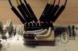
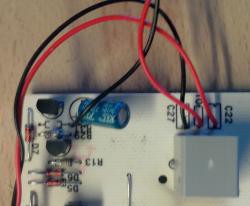
Second, I made a little bit more of soldering. I had to redo the "connector" I previously made for the keypad as it is blocking everything when the phone is closed. I still had to bend the pins to get the room I need. I also tapped directly on the original PCB to connect some jack connectors. I can now use the phone with the original connector :). Now I still need to solder the switch for the phone and see if I can reuse the buzzer (I doubt that I can have enough power to make it ring loud enough).
![]()
![]()
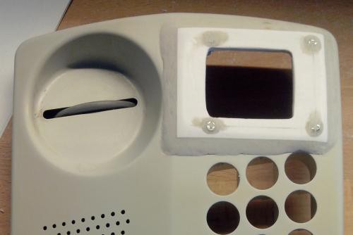
Third, today I decided that this week should be partly dedicated to the mechanical part of the build (mostly because I entered the ToxPhone in the Zero Contest, and I don't want to run out of time). So I made a bezel for the screen by using some PVC and epoxy putty (first time using it, it was pretty messy). I also integrated the bezel in the phone. I need to think about how to integrate the NFC reader (I also have to try to connect it and use it in the software). And I will start to paint the phone as soon as possible.
![The bezel installed and a little bit sanded]()
-
Reading the keypad (again)
01/20/2016 at 15:53 • 0 commentsSo, last time I've made a python class to handle the keypad. Then I thought : "why not trying to make a driver that will behave as a keyboard ?". It took me a couple of days but I was able to make it.
When I tried it, it wasn't always precise BUT, it's because the PCB is currently hanged on a poor and weak third hand, with the buttons just placed on top of it. When I want to press a button, I have to hold it and most of the time, I don't press it straight so it's moving a lot. I've added a software debounce in the driver but it may need some tuning. And I keep in mind that when it is placed in the phone, the buttons are driven by the holes in the case so it will be more stable thant it is now.
An issue I ran into is the usage of the GPIO. At start I was using one of the SPI_CE pin for one of the row but I will probably need it since the screen and the NFC reader use SPI. So I moved onto using both of the UART pins to free some more GPIO for other stuffs (and since I don't use UART, I can skip it). Then the issue arose. The GPIO 14 boot by default in UART_TX mode, which is pulled to HIGH and can't be changed later with the gpio.h library. Luckily, ArchLinux on Raspberry Pi implements device tree. Following this instructions, I was able to make a device tree overlay to initialize all the pins I wanted with pull-downs.
You can find the driver and the device-tree overlay on Github. The driver is not compiled yet so if you want to use it, you have to get the kernel sources and make a "make" in the folder where you put it. You may also want to edit the sources to change the GPIO to fit to your wanting. You can also change the keypad mapping.
Later, we will talk about Tox using PyTox as we already made a small working example.
-
Starting the ToxPhone
01/05/2016 at 21:48 • 0 commentsSo after a few weeks of discussing and procrastinating, we decided to step up in creating a ToxPhone (some kind of secured landline in layman terms). I found an old phone in my attic, from 1995, and decided to start today tinkering with it (while some components are being delivered)
I was surprised at how easy it was to open. Just one screw. From there I had a look at the mainboard and spotted the PCD3310 which is a pulse and DTMF dialler. Its only goal is to communicate with the phone network and manage the keypad. From there, I knew what I had to do if I wanted to keep the original keypad : just desolder the chip and connect the rows and the columns from the keypad to the Raspberry Pi. All the components had their pins bent after being soldered so I had to be a little bit violent with the PCD3310. Some of the pads got off but I was able to make a reliable connection anyway. I decided to take away some passive components aroud the PCD3310 to gain some place and liberty. The datasheet helped me to identify the rows and the columns of the keypad.
I took a small piece of a breadboard to make some kind of connector. Once soldered, I took time to install a brand new Arch Linux on the Raspberry Pi. I had to fight a little since Arch Linux is not packaged anymore in NOOBS. I followed this page for the installation on an SD card and then this page for setting a chroot with QEMU in order to add some software (I couldn't connect the wifi at first boot : no wpa_supplicant). From there, I was able to set up a SSH connection and start writing some python.
Using the Rpi.GPIO python library, I wrote a small python class (Keypad) that configure the GPIO and find what key have been pressed. All rows are connected into interrupt-driven pins with pull-down resistor enabled. The columns are configured as outputs in high-state. When a key is pressed, one of the rows is pulled to high-state, which trigger an interrupt. The callback for this interrupt will turn off and on each of the column pins. During this change of state, the pin that have triggered the interrupt is measured again. If it goes to the low-state, that means that we have disabled the column corresponding to the key pressed and we can then deduce the key that have been pressed.
It's basically how the Keypad library for Arduino works. The only difference is that I used the internal pull-down resistors of the Raspberry Pi and I used interrupts to avoid using some polling systems (too cumbersome and cpu consuming).
 RodolpheH


