-
Why I Shelved This
06/14/2019 at 20:26 • 1 commentThis project is dead because I'm not sure that it's safe.
If you recall - I don't blame you if you don't - this speaker works by pumping out a 40kHz square wave, then varying the duty cycle. The human ear would respond to the varying duty cycle. This means that the ultrasonic transducers are continuously emitting full power.
Unfortunately, there have been very few studies on how loud ultrasonic sounds affect people. I'm just not sure about connecting up a 400W power supply and pumping out a continuous, full power 40kHz sound. Because of the directivity of the wave, the volume might even exceed 140dB.
I don't even know how to measure the output.
Finally, we now have a cat. Cats' hearing ranges up to 64kHz, and I woudn't want to frighten or deafen her.
Thanks to everyone who gave me ideas and encouragement while this project was alive!
-
Why The Arduino Due?
03/04/2016 at 16:53 • 0 commentsI chose to use the Arduino Due at a very early stage of this project. Partly I fell into it from curiosity after previously using an Arduino Uno, but there were a few concrete reasons too:
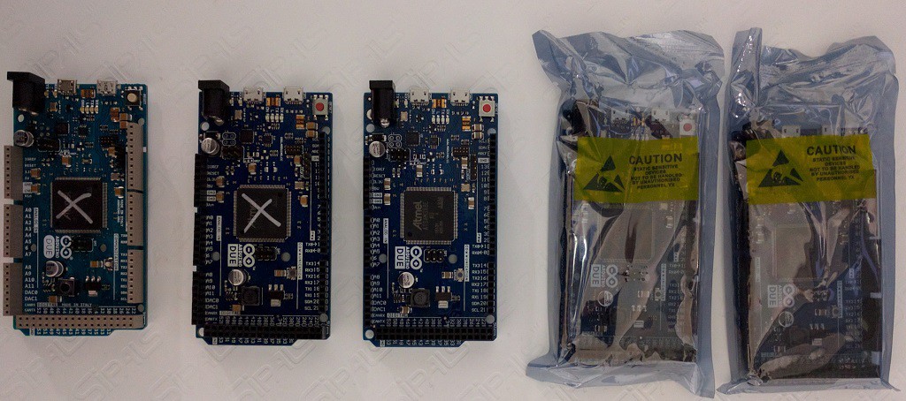
- Cheap. Through injudicious application of 12 volts, I've killed two boards already. Blowing up $100 equipment would be stressful, but since the Due can be had for 20AUD (ebay, aliexpress), it's more nuisance than disaster.
![]() Five Dues. Two dead. One in use. Two more ready to go.
Five Dues. Two dead. One in use. Two more ready to go.- Range of peripherals. The Due's SAM3X8E (link to 1459 page pdf datasheet) has peripherals I need and a bunch more that are just convenient.
- ADC: To digitize the incoming signal.
- PWM: For output of the 40kHz, variable duty cycle signal.
- USB: For programming and debugging.
- SPI: Desirable for running all kinds of peripherals.
- DAC: outputting an audio signal is a useful debug tool.
- Timers: useful for generating audio tones.
- GPIO: The Due has loads of GPIO pins for reading user input and flashing the odd LED.
- And more I won't use for this project: CAN bus, Ethernet, IIC, external RAM, external Flash, SDCard reader/writer.
- ARM Architecture. I've been wanting to work with ARM for a while.
- Fast enough. The 84MHz system clock allows the duty cycle of the 40kHz PWM signal to be varied in increments of 1/84,000,000's of a second. This allows for 2100 settings of the duty cycle, approximately 11 bits of precision.
- Ease of use. The community (arduino.org) is great and vendor tool support (Atmel Studio IDE, Atmel Software Framework) is more than adequate. There's lots of example code, and the ability to program via USB makes it simple to get get started.
Maybe the Due wasn't the best choice for this project, but it's working out pretty well none-the-less.
-
Prototype
01/26/2016 at 02:03 • 2 commentsI finished step 1 from my plan.
![]()
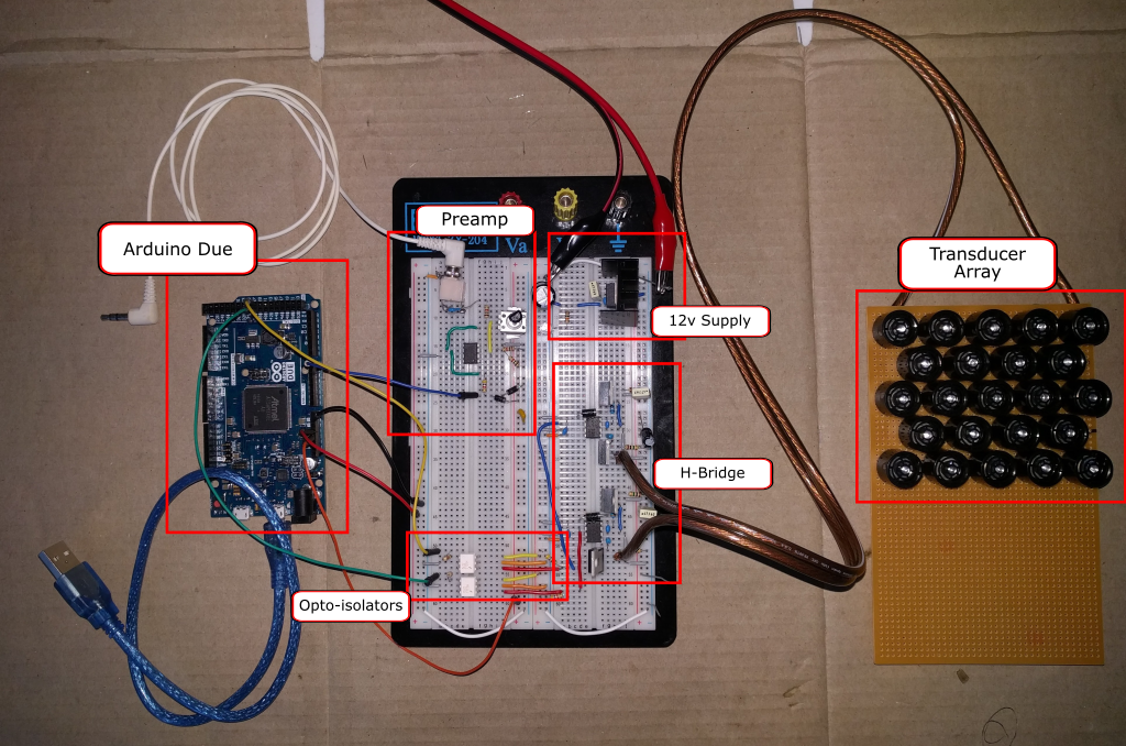
It works! The speaker shows a directional effect, and it's quite loud, at least in my work area, with the supply cranked up to 30V.
System Design
This is the design for the signal processing path:
![]()
- Input signal passes through an op-amp to amplify it to the 0-3.3v range that is suitable for the Arduino Due's ADC.
- The ADC does what is supposed to do: it converts the analog signal to a digital one. The Due has a 12bit ADC. There's a little noise, which, as far as I can tell limits its effectiveness to somewhere between 9 and 10 bits. That's OK because the later PWM stage only has a 10-ish bit resolution.
- The Arduino's PWM generator is set to produce a 40kHz waveform. Every 1/40,000th of a second, the Arduino sets the PWM duty cycle based on the reading from the ADC unit.
- The output of the PWM is used to drive an H-bridge, effectively amplifying the few milliamps at 3.3v from the Due to transducer driving level.
Schematics
I'd like to post more about the individual sub-systems, but for now, here are schematics covering the bulk of the electronics, and which may help explain a little more. The schematics are online in EasyEDA.
Preamp
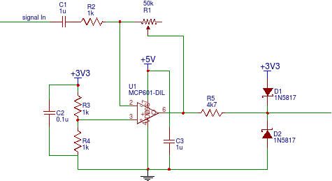
The preamp uses an op-amp to amplify the incoming signal to the 0-3.3v range. I first used an LM324, but discovered that, despite the datasheet, it does not give very linear output in the region of its negative supply rail. Hmmph. I swapped it out for an MCP601 and it works fine.![]()
The design was somewhat inspired by the ElectroSmash PedalSHIELD, but greatly simplified. Greatly. It was just much easier to do a single-channel inverting design rather than a dual channel design, and frankly, I don't really understand the feedback mechanism used in the ElectroSmash pedal. I did, however, copy the input protection mechanism of a 4k7 resistor and reverse biased schottky dioides to ground and 3.3v.
This circuit seems a little noisy. I need to investigate that further. In a future iteration, I'd like to try generating a negative supply rail, as the PedalSHIELD does. This will allow the use of a higher precision op-amp.
The preamp is powered from the Arduino. In the breadboard prototype, the Arduino is powered by the USB port.
H-Bridge
![]()
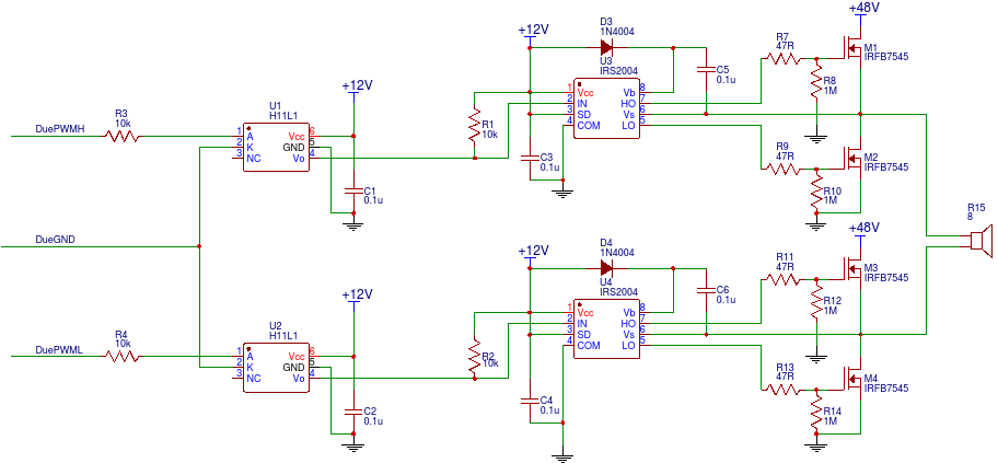
This is a fairly standard H-Bridge circuit. Let's review it from the left side (input) to the right side (output).
The Arduino PWM generator produces complementary outputs PWMH and PWML. The way this is configured, one is simply the inverse of the other. It would be possible to just use one PWM output and invert it, and I may try that in future.
The signals pass into two H11L1 opto-isolators. I decided to use opto-isolators after toasting two Arduinos in earlier experiments. Internally, they have an open collector transistor which turns on whenever the input current is high enough, and turns off whenever the input current drops sufficiently. Because the H11L1s cannot provide current the output is pulled high by R1 and R2. The effect of this is that the input signal from the Arduinos is inverted, amplified to 12V and delayed by 1 microsecond.
The H-bridge is driven by two IRS2004 half-bridge drivers. These contain the logic to alternate between high and low sides of a half-bridge, ensuring that the supply voltage and ground are never connected together. They also are able to use an external diode and capacitor to generate the voltage needed to drive the high side MOSFETs efficiently (48V + 12V in this case).
The opto-isolators and half-bridge drivers cannot use the 48V supplied to the speakers - it's too much. The H11L1s have a 16V maximum and the IRS2004s have a 10V minimum, so on the breadboard prototype, an LM7812 is used to derive 12V from the bench power supply (not shown).
The prototype uses four IRFB7545 N-channel MOSFETs. These have cause less than 0.1 volt drop at 10 amp load, which means < 100mW power dissipation even at that point. They run very cool. 47R resistors protect the drivers from the gate in rush current, and 1M resistors pull the gates down to zero in the absence of drivers. The transducer array is connected directly across the bridge.
At this point we have amplified 3.3v at a few milliamps to potentially 48v at tens of amps. Not bad.
Confessions and Next Steps
Actually, this is my second prototype. The first one worked, but I was unhappy with several aspects of it and so decided to do it again from scratch. This new one:
- Pre-amp is completely reworked, including better input protection.
- Opto-isolators protect the Due from higher voltages.
- The breadboard is much more nicely laid out.
- Drives a larger array of transducers.
Next up, will be to move away from the bench power supply. I have two 48V, 10A power supplies ready to unpack and wire up to connect to the mains.
-
Baby Steps
01/22/2016 at 21:44 • 2 commentsI'm constantly torn by how "finished" a product I ought to be aiming for. It's very tempting to over polish, but I'm not looking to produce a mass-market device. Instead I should focus on the requirements, then plan how to get there.
Requirements for V1
For March, I want to build a device that
- has two, independent channels (not really stereo, as mostly people will only hear one channel at a time).
- Each channel ought to have its own volume control
- Each channel ought to be output to its own speaker
- is reliable enough to support Mitchell's practice and performance sessions without needing tinkering.
- is easy to operate so changes can be made on-stage if required
- On-off switch on front panel
- Easy to twiddle volume knobs controls
- Some kind visual indication of current performance, such as a VU meter.two or maybe three devices that work reasonably reliably.
- Safely packaged to avoid electrical and physical hazards.
Future Versions
Things I don't need to do
- MIDI, Internal Synthesizer.
- SDCard for sound files.
- Touch screen.
The Plan
Here's the outline of how I want to get from where I am to V1
- Prototype single channel on a breadboard
- Use bench power supply and power over USB
- Build input circuitry, with amplification and voltage protection for the Arduino.
- Build single channel output circuitry
- incorporate opto isolators
- test a 4x4 transducer array, see if an inductor would help
- build 5x10 or 7x7 array
- Figure out mains power supply
- Carefully consider safety aspects
- Build it, for real. It should supply 48v, 12v and 5v power.
- Build dual channel input
- lay out circuitry in diagram first
- build on perfboard
- Build output channel
- lay out circuitry in diagram
- build on perfboard
- Build transducer arrays.
- 2x 100 or 200 transducer arrays
- test and iterate
- Build an enclosure.
- Stand back and admire the work.
- has two, independent channels (not really stereo, as mostly people will only hear one channel at a time).
-
Debug Amp/Speaker
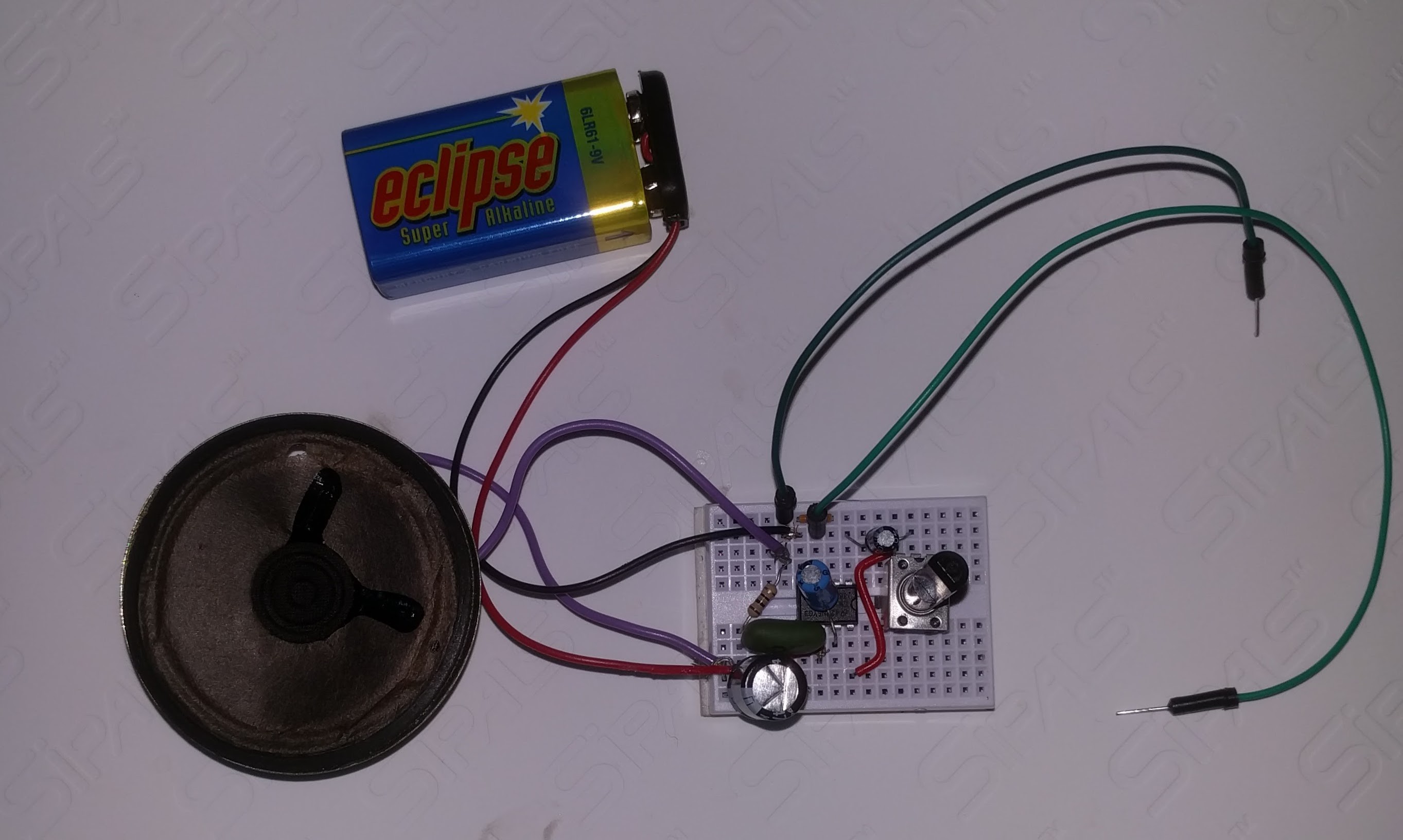
01/19/2016 at 11:47 • 0 commentsI made a little amp to help debug the audio input / processing side, based on the application notes section of the LM386 datasheet. It consists of an LM386, a 9v battery, an old 8Ω speaker and a handful of capacitors and resistors. I added a 50kΩ pot for gain control.
And here it is built on a mini breadboard:
![]()
It plays Nouvelle Vague just fine.
-
A Very Short History of Ultrasonic Directional Speakers
01/06/2016 at 09:14 • 0 commentsThis log is a summary of what I've found about directional speakers.
Joe Pompei and The Audio Spotlight®
The modern directional speaker began with Joe Pompei at the MIT Media Lab. Large parts of his 2002 PhD thesis go straight over my head, however there is a lot of good information in there, including a summary of previous research into directional speakers (spoiler: the military did a lot of work with sonar), and a human-readable summary of the math.
Pompei combines two ideas to produce a directional speaker.
First, sound waves are directional if the width of the wavefront is much larger than the wavelength. Middle-C (262-ish Hz) has a wavelength of 1.32m, so if a speaker were, say 10m wide, you might be able to get a directional wavefront from it. Ultrasonics however have much smaller wavelength - about 8mm at 40kHz - so reasonably sized speakers will produce a directional wave front.
Second, ultrasonic sound waves will demodulate in air. The resulting audible sound is much quieter than the ultrasound that generates it.
Joe Pompei called his speaker the Audio Spotlight® and founded Holosonics to produce it. There are a number of YouTube videos showing off the speaker: this one with Joe Pompei causing trouble in the library is my favorite, although this other one has some more technical details.
Kazunori Miura's Ultrasonic Directive Speaker
In March 2011, Elektor Magazine published an article by Kazunori Miura describing a directional speaker built from ultrasonic transducers. It was the inspiration for this project.
Briefly, Miura discovered that using pulse width modulation over a 40kHz square wave carrier produced a better result than several other schemes. He also seems to have pioneered using those 16mm transducers from ultrasonic range finders. The article has lots of useful hints about construction too, including the need to determine the polarity of the transducers (more on this later).
Miura's resulting device looks a lot like a class D amplifier (explanatory video here). The incoming signal modulates a 40kHz wave, which is then pumped through a MOSFET H-bridge to drive an array of ultrasonic transducers. If one were to replace the array of transducers with a low-pass filter and an audio speaker, it would look a lot like the the circuit used in the class D amplifier Wikipedia article.
As far as I can tell the differences between Pompei's and Miura's devices are:
- Pompei uses amplitude modulation (AM) while Miura uses pulse width modulation (PWM). AM can use power more efficiently since the power required to produce the ultrasonic wave is (approximately) proportional to the power of the audible signal, while the PWM scheme uses full power all the time. AM also requires more sophisticated processing.
- Pompei uses an array of circles of piezo-electric film, about 40mm across (as far as I can tell) while Miura uses 16mm piezo electric transducers. The 16mm transducers are relatively common and simple to mount on a PCB interface with (ie. solder to the terminals). I suspect that using the film is fiddly.
- Pompei's device runs at 65kHz, while Miura's runs at 40kHz. 40kHz is audible to dogs, while 65kHz is not. Cats, however, can hear both. Neither frequency seems to have any effect on humans, even at quite high levels, but there hasn't been conclusive research either.
Kazunori Miura is selling kits from his website. They're quite good value considering that they include the transducers, which are a little difficult to get hold of.
A Sidebar about Elektor
If you're into hobbyist electronics you should probably subscribe to Elektor. Every issue has two or three neat ideas that get me thinking. Look in the Jaycar Catalog, page 63 for a discount code.
And Others
SoundLazer is likely a device that Hackaday readers have heard of. The first SoundLazer device was a successfully funded Kickstarter project, with all backers receiving access to schematics and parts lists, however these are not available to non-backers and the company is now focused on building and selling complete products.
The LRAD is a directional loud hailer device/crowd-control device/weapon sold to governments for use by the military and police. Here's inventor Woody Norris giving a demonstration of his newer devices in a TED talk, though it is extremely light on technical detail.
In Summary
If what you want is a working directional speaker, there are many good options for kits and pre-built devices. However, I'm going to build my own. It's more expensive, but I'm enjoying the process.
-
Why This is Being Built, and When the Deadline Is
01/06/2016 at 08:33 • 0 commentsThis all came about as a result of conversations with my son.
Mitchell is doing his Bachelor's degree in Music at the University of Western Sydney and this year will be putting on a performance as part of a course named "Sound and Performance: Expanded Practice". The university describes it in this way (bolding added by me):
This unit offers students the opportunity to plan, prepare and perform a substantial artistically and technically challenging performance project as featured artist. Students are required to expand their performance practice by utilising electroacoustic and/or multimedia and/or theatrical elements...
When he is assessed, Mitchell gets credit for his performance and any novel "elements" that he uses, but doesn't get credit for building these elements. In other words, it's not cheating if Dad builds it for him. It would even be fine for Mitchell to just go buy something off-the-shelf.
Mitchell had been interested in highly directional speakers for some time. I'm fascinated by them too: usually an audience has a shared experience of a performance, but directional speakers can give different parts of the audience different experiences.
After a bit of Googling though, I was hooked. I had a lot to learn, it wasn't going to be cheap, but it does seem to be something that I can accomplish.
That was October 2015.
Mitchell's performance is May 2016, but he should have a solid prototype before March in order to allow him to develop his performance.
Wish us luck.
Ultrasonic Directional Speaker v1
Producing highly directional sound from 40kHz ultrasonic transducers
 Alan Green
 Five Dues. Two dead. One in use. Two more ready to go.