 Bill Peterson
-
1Overview
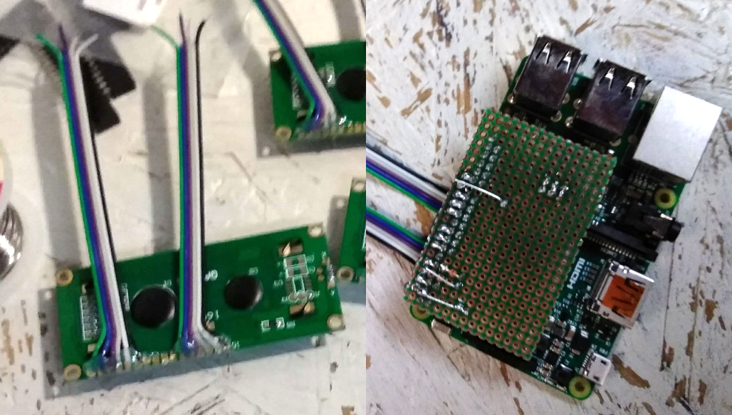
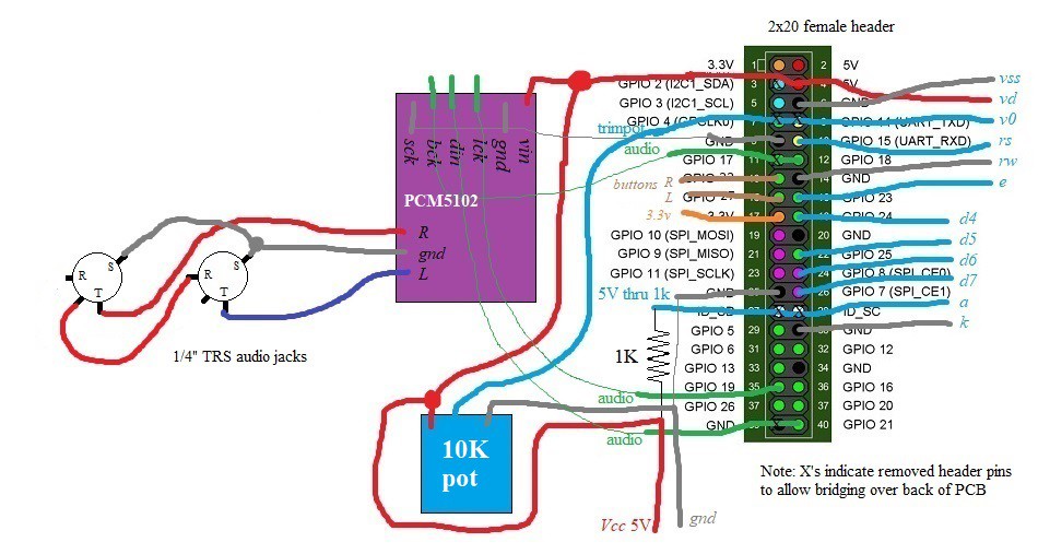
The image and (very crude) schematic below show the overall construction of the electronics for the SquishBox. The components are all attached to a rectangular piece of perfboard that plugs directly onto the Pi's GPIO header. Since we're using cheap one-sided perfboard, all the components are soldered to the same side, so the resistor, DAC, and trimpot will fit between the Pi and perfboard, and there will be room inside the enclosure for the LCD on top. The 2x20 header creates a bit of a barrier to the layout, but rather than wrapping wires around the sides of it and making a complicated mess, you can strategically remove a few unneeded pins, strip some extra insulation off your wire, then thread it through and over the back of the header as shown in the image below. The X's in the schematic show where pins should be removed from the header (you can pull them out with needle-nose pliers). The enclosure-mounted components - audio/DC jacks, buttons, and LCD - are connected to the perfboard with strips of ribbon cable, which I like because it keeps thing tidy and the color-coding is helpful for making the right connections.
-
2Connecting LCD
Two strips of ribbon cable are used to connect the LCD pins to the perfboard - this is necessary since we can only solder on the top side of the board, so the wires have to be inserted from the bottom, and also allows for the LCD to be mounted in the enclosure body. Hot glue should be used for strain relief at both ends of the ribbon cable, or the wires will definitely tear out while you're assembling the components.
![]()
-
3Perfboard Components
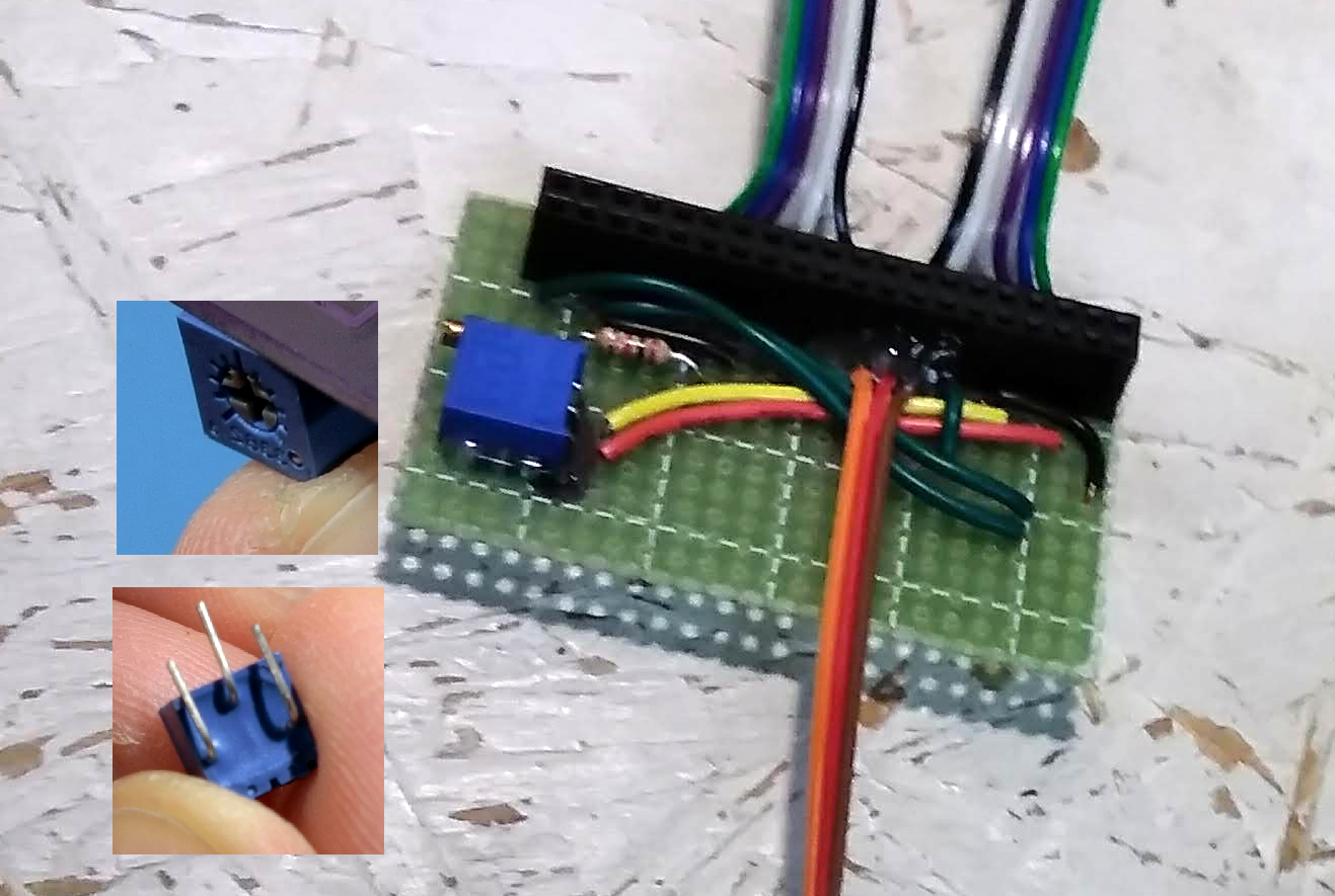
Solder the 2x20 female header into the perfboard, followed by the resistor and trimpot. Mount the trimpot at a point where it will be accessible by a thin screwdriver inserted between the USB ports. The trimpot shown in the inset images is a better choice than the one in the larger image, as a cross-head screwdriver will seat more easily. Bend the pins to one side as shown so you can mount it at a right angle to the board edge. Test fit the location of the DAC in the board and solder in the jumper wires for its connections, but don't solder it in place yet.
-
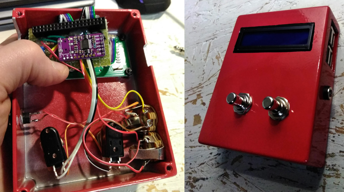
4Panel-Mounted Components
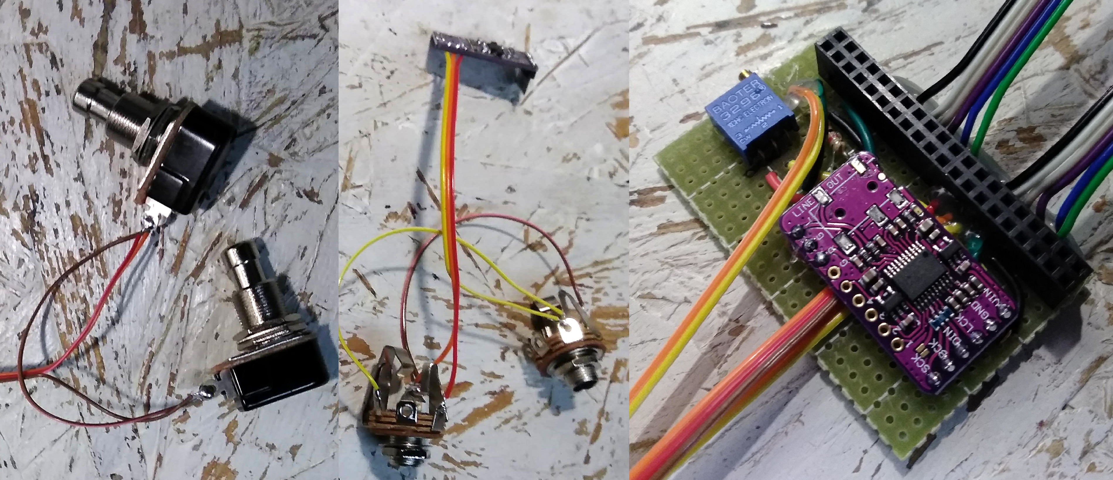
Attach the buttons and DC jack to the perfboard and the audio jacks to the DAC using strips of ribbon cable. Hot glue at the board connections is a good idea. Although in the images below I soldered wires to the jacks and buttons while they were hanging loose, it may be easier to install them in your enclosure first and then solder wires. Some components may require this, such as the DC jack for example. The DAC should fit between the perfboard and Pi, but the headphone jack can sometimes make contact with components on the Pi. To prevent this, cover the headphone jack with tape, or very carefully desolder it or cut it off with flush cutters. Now you can solder the DAC to its spot on the board, pinching the wires to the audio jacks underneath it to keep them from coming loose.
![]()
-
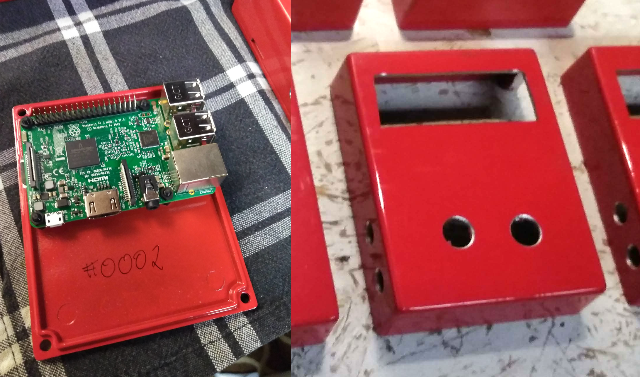
5Preparing the Enclosure
Screw the hex standoffs into the Raspberry Pi and position it on the lid. You may need to file a notch in the lip of the lid for the SD card so it doesn't get snapped off. Mix some two-part epoxy and put a blob on the bottom of each standoff, press the Pi back down on the lid, and leave it alone for ~24 hours so the epoxy can cure. Now you should be able to mark where to put the openings for the USB ports, SD card slot, LCD mount, buttons, and jacks.
A stepper drill bit is very helpful for drilling larger-sized holes in the enclosure. The square openings can be cut with a handheld jig saw - aluminum is soft enough that a regular blade will do fine. Mask around the edges with tape so you can see where to cut and to protect the finish. Drill holes at the corners of the openings, cut along the sides, and file the edges square.
-
6Mounting Hardware
Screw standoffs into the LCD mounting holes and epoxy the LCD into place as you did with the Pi. You can cut the standoffs with flush cutters or file them down on a fine sanding block to get them the right height. Screw on nuts and washers to mount the rest of your hardware. Be careful not to tear any wires - once things are secure in the enclosure they should be fine. Plug the perfboard assembly onto the Pi - you should have enough slack in your wires to get a decent grip, and screw on the lid of the enclosure. Your SquishBox is finished!
-
7Software
Obtain a Raspberry Pi OS image (lite version recommended) and follow the instructions to burn the image to a microSD card. Open the new /boot partition of the SD card on your computer and edit the config.txt file, adding the following lines at the end (the first connects the DAC, the second keeps the processor in performance mode):
dtoverlay=hifiberry-dac
force_turbo=1
Next, create an empty file named ssh (no extension) to enable remote connections on startup. Create a second file called wpa_supplicant.conf with the following contents (replacing your-network-name and your-password with your specific values):
country=US # change to your country code, list at link below
# https://en.wikipedia.org/wiki/ISO_3166-1_alpha-2#Officially_assigned_code_elements
ctrl_interface=DIR=/var/run/wpa_supplicant GROUP=netdev
update_config=1

network={
  ssid="yournetworkname"
  psk="yourpassword"
}
Insert the SD card and plug in your SquishBox. Allow a good 5-10 minutes for the Pi to complete its initial boot and resizing of the root partition. Look at your wireless router's settings to determine what IP address the Pi is using, and connect remotely using an ssh program. Once logged in, you can run the script to install the necessary software by entering
curl -L git.io/squishbox | bashThe first time the script runs you will be prompted to reboot so your sound card can be activated. Run the script again after rebooting, and you'll answer a series of prompts. The default options will work fine, except when you are asked to select your hardward version, make sure to choose the "v2/homebrew" option. Once you've answered all the prompts, setup will proceed without any need for further input. Reboot when setup is finished and enjoy your SquishBox!
Discussions
Become a Hackaday.io Member
Create an account to leave a comment. Already have an account? Log In.