-
1Step 1
- First solder the headers onto your Arduino Nano board. Notice that I soldered the ICSP header onto the bottom since I'm using it to solder the serial lines of the LCD to.
- If your joystick and SD card breakout boards come with angled headers, like mine did, then replace them with straight headers.
- Cut the perfboard down to 39x18 holes
- If you got a cheap Nano clone like I did then don't forget to flash the Arduino bootloader. Instructions found here: http://www.instructables.com/id/How-To-Burn-a-Bootloader-to-Clone-Arduino-Nano-30/
-
2Step 2
- Screw the spacer onto the SD card board.
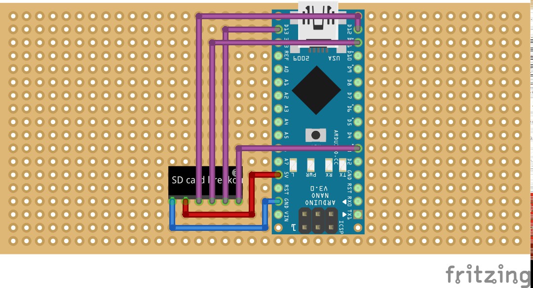
- Solder the Arduino and SD card breakout onto the perfboard. Notice their placement in the image.
- Solder the VCC (5v) and GND lines of the SD breakout board to the Nano
- Complete the data lines of the SD board:
- CS to D3
- SCK to D13 or ICSP3 (I connected the data lines to the digital pins of the Nano to make my life a little easier since I have the LCD connected to the ICSP header)
- MOSI to D11 or ICSP4
- MISO to D12 or ICSP
![]()
-
3Step 3
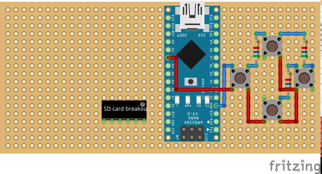
- Solder the pushbuttons and resistors onto the perfboard as shown in the image. Shared pins of the buttons go horizontal.
- Complete the connections of the buttons and the resistors.
- Common button pins go to A2, series resistors go to GND
![]()
-
4Step 4
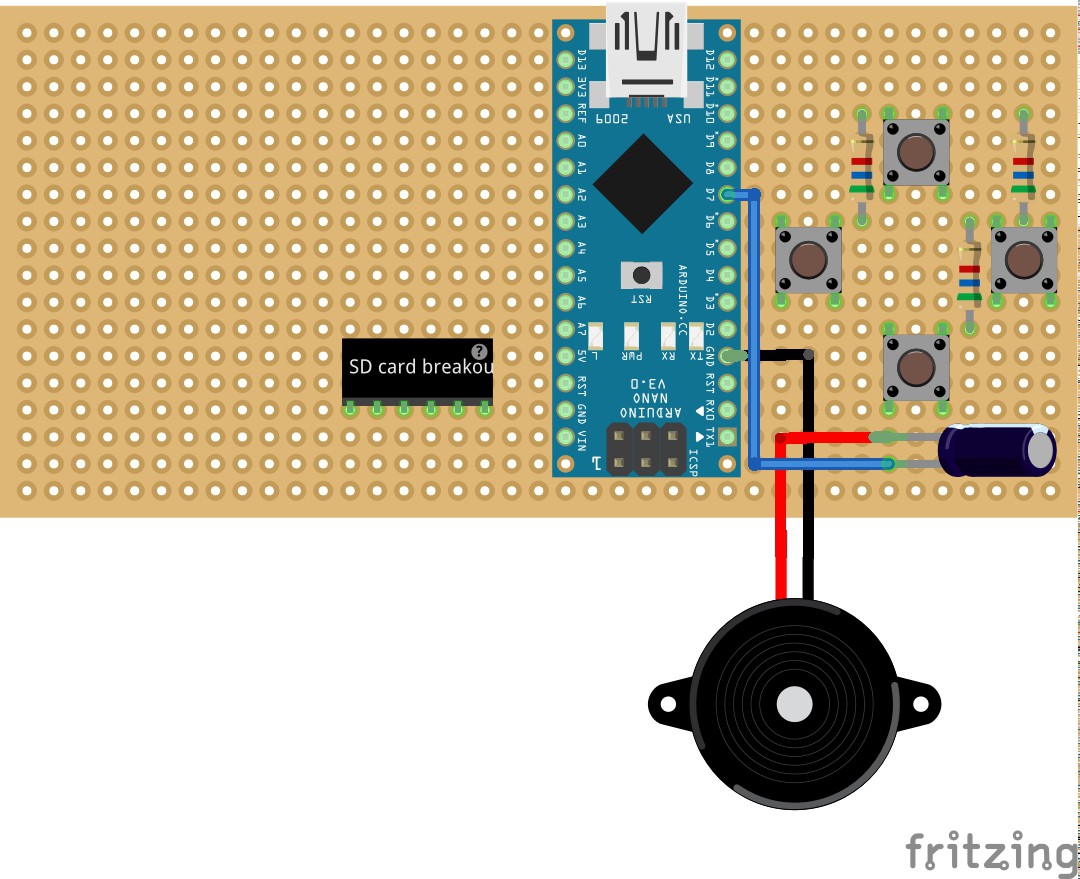
- Solder the 1uF capacitor and piezo speaker onto the board. Depending on the height of your capacitor you may want to bend the leads so it lies on its side.
- Connect the positive end to D7 and the other end to GND
![]()
-
5Step 5
- Solder 10 wires or a 10 stranded ribbon cable onto the LCD pins. Notice that pin 1 is the pin closest to the edge of the screen and the solder connections indicate the bottom of the screen. You may temporarily have to remove the plastic bracket that holds the LCD's PCB in place.
- Now solder the LCD as follows:
- LCD 1 (/SC) to D6
- LCD 2 (/RST) to D5
- LCD 3 (RS) to D4
- LCD 4 (SCLK) to D13 or ICSP3 (I chose to connect the LCD to the ICSP header)
- LCD 5 (SDATA) to D11 or ICSP4
- LCD 6, 8 and 10 (VCC) to 3.3v
- LCD 7 and 9 to GND
![]()
-
6Step 6
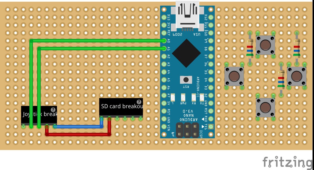
- Finally screw the spacer onto the joystick breakout board
- Solder the joystick onto the perfboard and connect VCC (5v) and GND
- Connect the X pot to A1 (Since the board is rotated X becomes Y)
- Connect the Y pot to A0
- Key is not connected
![]()
NANO-4096
An easy to build Arduino based gaming device with 101x80 pixel 4096 color LCD, 8 buttons, sound and SD card.
 Maarten Janssen


Discussions
Become a Hackaday.io Member
Create an account to leave a comment. Already have an account? Log In.