timonsku
-
Light Module V3
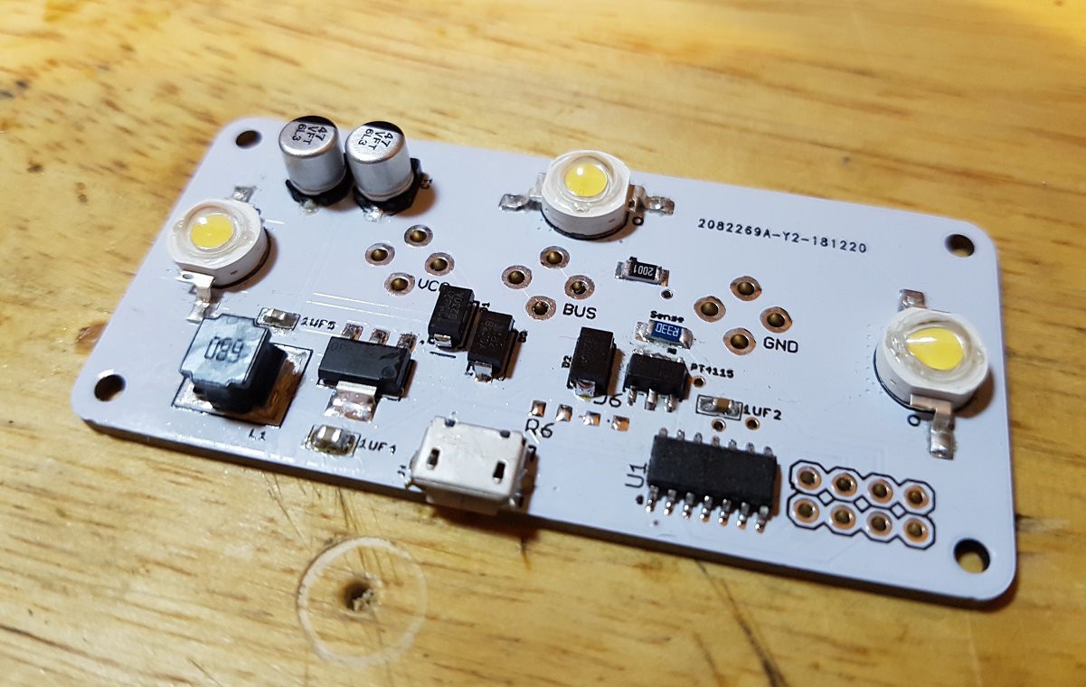
01/04/2019 at 17:02 • 1 commentThe new PCBs and components arrived this week (thanks again to LCSC for that) and I soldered up a module to test everything.
Everything fit and is working as expected which is great! I also tried out new fuse holders that a corrspondent from LCSC found for me, which are much cheaper than the fuse holders from Schurter that I used before. I feared they might not have the same strength as this was the main reason I used the expensive fuse holders so far but they were actually a bit stronger!
This is so far great news for my plan to produce a small round of light modules as it will drop the price quite a bit.
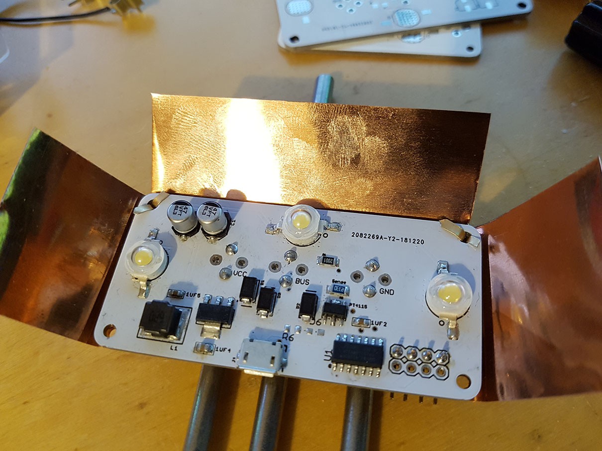
I did some new temperature tests as I now used a 2oz. copper PCB as planned. This did a lot for transferring the heat away from the LEDs, after a good hour of full on use the LEDs were idling around 60°c which is 20°c below their max. operating temperature.
I hope this helps a lot with LED lifetime which I found to be an issue previously.
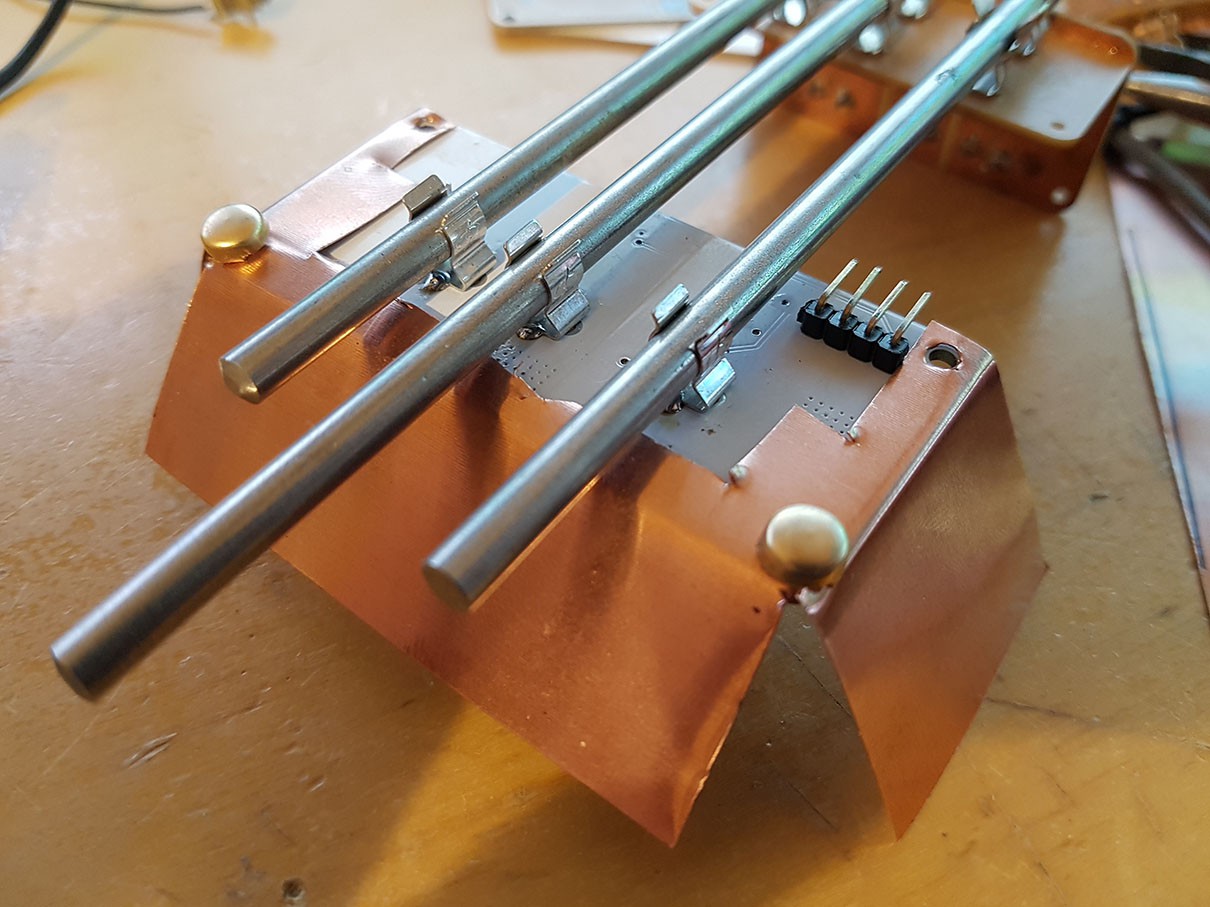
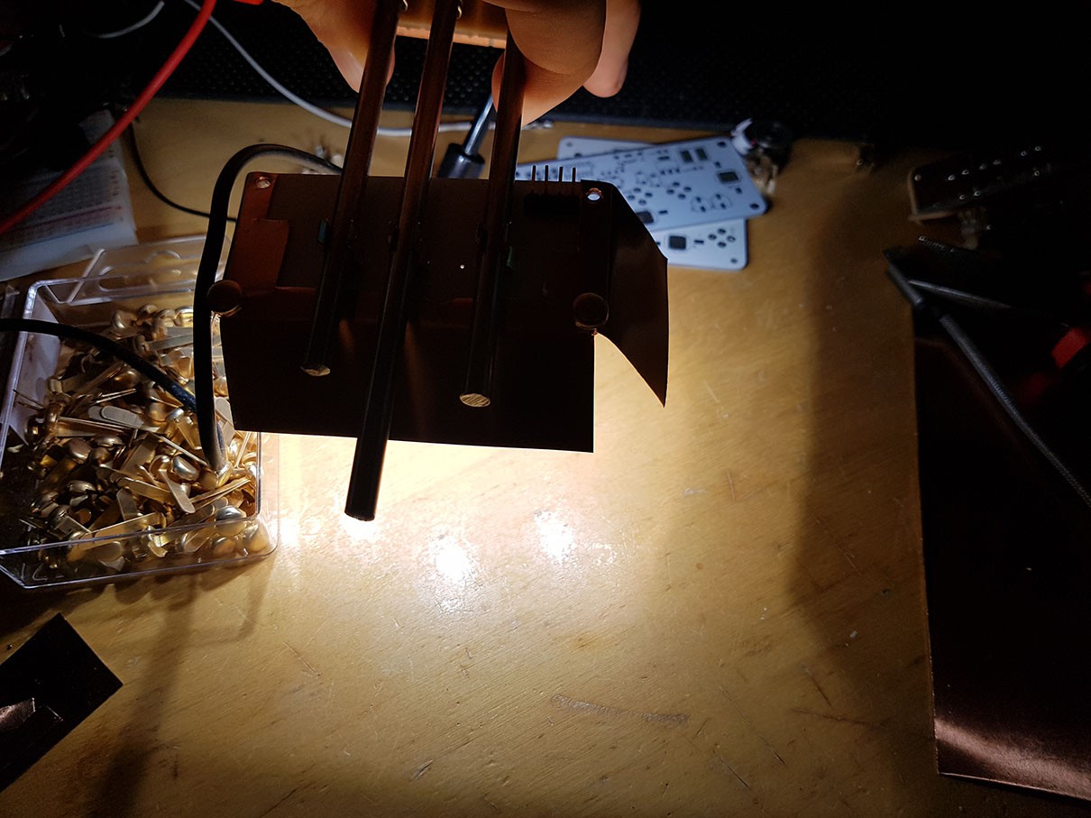
I also cut together a lamp shade for testing out the concept of using metal sheeting (copper in this case because I had it around) for a robust and reflective lamp shade. This worked out really well, I used paper fasteners inserted into the mounting holes which were holding the shade in place quite firmly. I wanted to test a fastening method that doesn't require metal bolts and nuts. This way attaching a shade is a lot faster and only requires material that you can find in practically any store that sells even the most basic office supplies and it actually looks kind of nice.
You don't have to use copper and brass of course, using zinc steel or stainless steel sheet metal works just as well. Paper fasteners are also available in zinc color.
Before anyone gets concerned, no the lamp shade does not short everything out :)
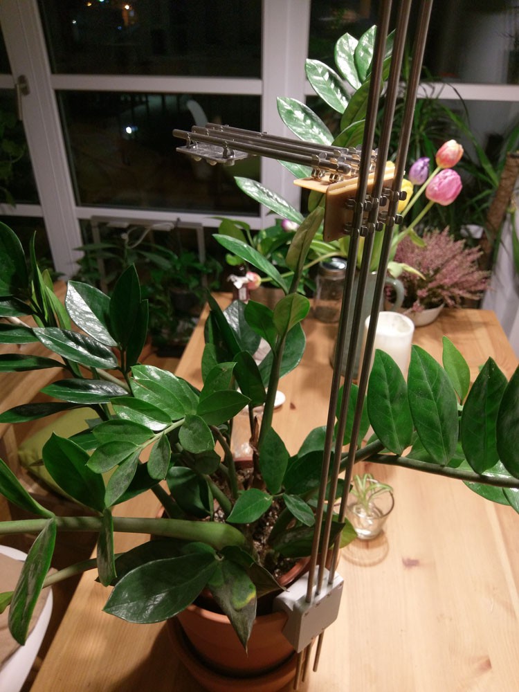
Even though the edges in this prototype are super bend up there are still about 3-4mm space between the shade and the rods.![]()
![]()
![]()
![]()
-
Back from the shelf and new prototype coming up
12/20/2018 at 13:09 • 0 commentsI had to put the project aside for the past 6 months, unfortunately, due to a high workload at the office and a long vacation in-between.
In the past few weeks I got more and more requests from friends and strangers if I could help them re-create at least the basic lighting setup to start growing food plants in doors. That gave me motivation to dive back into it.
Even better LCSC approached me a few weeks ago to help me out with components and PCBs.
This was a great fit as the main LED driver (PT4115) is from a Chinese producer and hard to get from trust-able western distributors. LCSC is one of the few reliable source that stock it. Getting all the other jellybean components from LCSC instead of AliExpress make the repeat-ability a lot better as well, its actually not that easy, with a reasonably long BOM, to get all the exact same components again from AliExpress as a lot of vendors just sell generic stock and tend to change manufacturers if one can't deliver for a while.
Here is the full BOM if anyone is interested: https://github.com/PTS93/MoAgriS-Modular-Agriculture-System/blob/master/BOM-LED-Module.csv
Given that I don't have to order every components in fixed multiples made the actual per piece cost a lot cheaper as well.
So thats nice. If that new design proves to be successful I may sell a few kits in the future if enough people are interested.
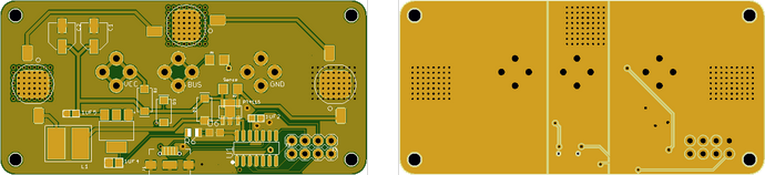
Here a render of the new LED board design.
During my testing in the summer I tried out various configuration. 2x3W, 2x5W, 2x1W. Anything larger than 1W was dying after a few weeks even with heatsinks attached directly to the heatsink pad of the LED.
1W LEDs work alright but the light output is a little too small so I went back and added a third LED to the module and made it slightly larger.
With 2oz copper boards I'm fairly confident to keep the LEDs well below their max temp. specs.
I also tested the communication via SDI-12 over the single wire and had great success with that.
I will post my test results once the boards and components arrive and I had the time to solder them up. Which will probably happen in the first week of January, until then I'm busy attending 35C3. I will be at the Hackaday assembly if anyone want to say hi.
You can find the new design files in my GitHub repo: https://github.com/PTS93/MoAgriS-Modular-Agriculture-System -
Motor module
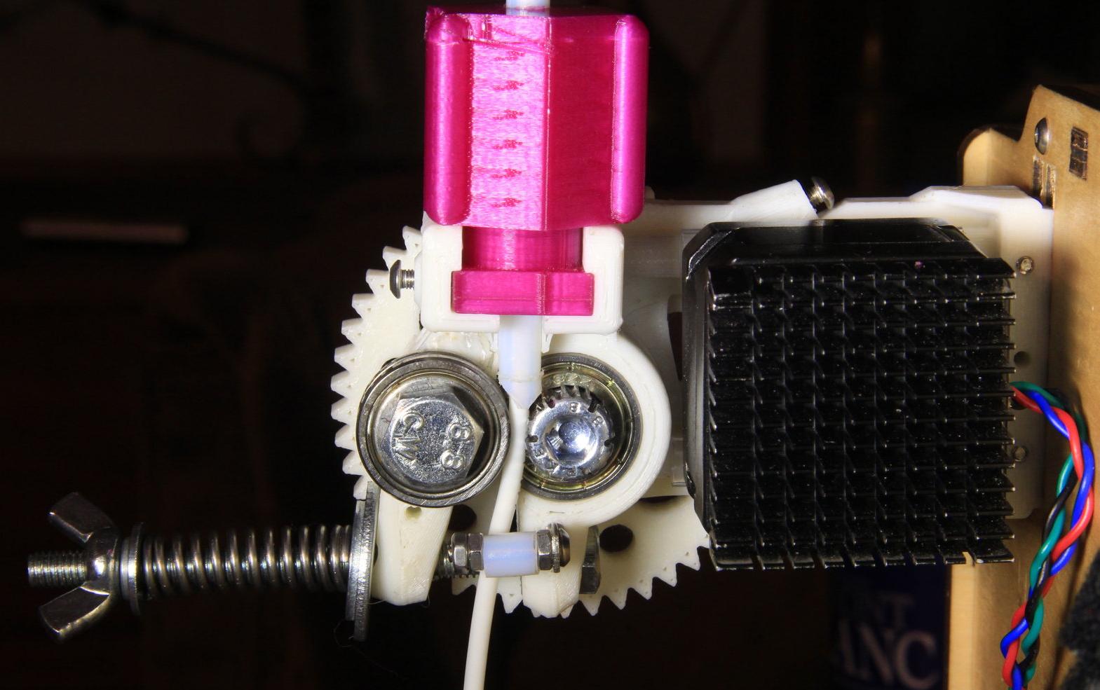
05/14/2018 at 20:51 • 0 commentsRunning my first test with the tomato made me quickly realise that I will need some kind of motor module to move up the arm that holds the light modules as the plant grows otherwise you will have to adjust the light position every other day.
I already have a design in mind, first I thought about adding a threaded rod in the middle but that makes keeping electrical contact with the rod a bit hard as the fuse holder can easily grip into the threading and either make the module stop or jump of the rod and loose connection.
Instead I will leave it as is and use a clamping mechanism to press motor with a U wheel bearing on its shaft against the middle rod with a second U wheel bearing pressing from the other side. Somewhat similar to how some 3D printers grip onto and move filament into the nozzle.
![]()
I'm not sure on the motor style yet. I don't think I want to go for high precision in any way but having +/-1mm precision would be nice because then you could use this platform for really large cable free CNC portal setups! Think about it, the motors can get control signals and power over the rods that give the whole thing structure. You could easily built a few meter long setups on your ceiling without needing a huge cable track moving along with it. I think that could be really powerful.
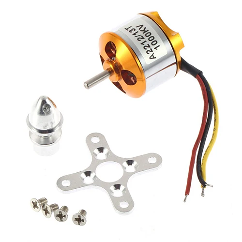
So I was thinking of either using small stepper motors or drone BLCDs, they are pretty cheap, small and have high torque, potentially moving heavier loads quite quickly. With very few steps they lack precision but you can use encoders to mitigate that and actually make them really precise. Though I will probably go with a more low cost sensor solution to stick with the style of the project. If it doesn't work out I'm fairly confident that standard steppers will do the work just fine.
![https://ae01.alicdn.com/kf/HTB19w2geTnI8KJjSszgq6A8ApXa6/1pcs-A2212-Brushless-Motor-930KV-1000KV-1400KV-2200KV-2700KV-For-RC-Aircraft-Plane-Multi-copter-Brushless.jpg]()
-
Indoor Tomato Outperforming The Outdoors
05/12/2018 at 11:56 • 0 commentsMy experiment started a few weeks ago to see how the growth of a tomato from the same pack of seeds would compare by being grown indoors with MoAgriS vs. being grown outdoors in the sun.
The difference is quite staggering. Even though I live in a very mild area where there is even wine growing and the fact that we had the warmest April in the history of temperature recording; The outdoor tomato(s) are very far behind compare to the indoor tomato.
Both plants started out as seedlings in the inside grown with the lamp modules, when it got regularly over 20°c outside and not much under 15°c at night I put all but one tomatoes outside in a spot that would get sunlight all day. While the indoor tomato would get light for about 10h a day (which of course comes with a slightly increased energy bill vs free sunlight outdoors, so if you can grow outside, I always recommend that economically and ecologically wise).
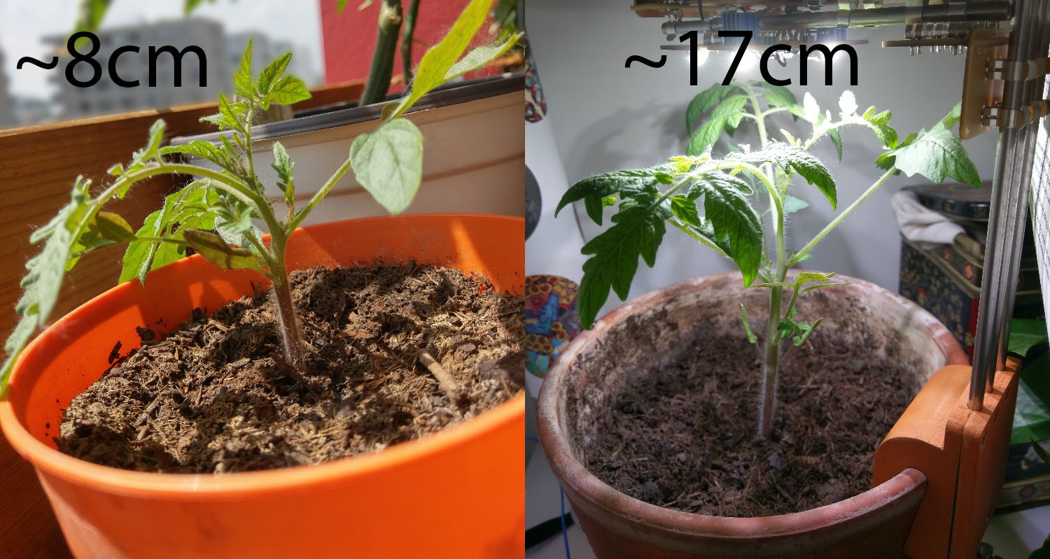
On the left you can see the outdoor tomato, on the right the MoAgriS grown tomato.
![]()
The difference is quite staggering. The indoor tomato is about twice as large, same goes for branch length.
Though it remains to be seen how much this will affect amount of fruits and if the indoor plant will develop fruits at all. While the stem thickness seems healthy for the indoor plant a large plant does not necessarily mean that the plant will bear a lot of fruits, it could also mean it tries to reach the light and puts more energy into growing fast and produces a very thin stem..
Though I think this time around this doesn't seem to be the case, usually the plant will bend towards the light when there isn't enough and the light source is not perfectly above the plant, when I offset the light position for a day the plant would not alter its growing angle or the angle of its branches to get more light.
I did some measurements with a lux meter to see how the new LEDs mentioned in an earlier log perform in terms of light output. The results are pretty great. I measured more than 40k Lux on two 3W LEDs 5cm away. Still far away from the brightest sunlight which is about 100k Lux but given that you never get a perfectly sunny day every day and you can easily add a few more modules to the plant to maximise light output.
I think is might still perform better than growing outside given the consistency of the light output and the consistent warmth inside, plants don't grow if the temp. drops below a certain threshold which is around 15°c for many plants growing in the Mediterranean.
I did not use the automatic watering for this particular plant so far as the water consumption at this stage is very minimal and the sun is not drying out the soil so you only need to water it every few weeks, not a very good test case for watering but this will change once the plant hopefully start bearing fruits.
-
Pump module
04/15/2018 at 22:54 • 0 commentsI designed a a first prototype for the PCB that will hold the pump and also be responsible for controlling it.
I wanted the pump to be just as integrated into the system as everything else so I didn't want it to sit somewhere on the floor but rather sit on the rods as well. So it was also kind of obvious to integrate the pump into a PCB together with its controller.
Totally legit footprint checking
![]()
Having native USB on the SAMD11 is really neat. I can debug a module without needing a programmer or USB to UART adapter.
The module is pretty simple. The base structure for every module is a SAMD11 loaded up with a bossac compatible bootloader, powered by a 3v3 LDO and programmed through its USB pins.
For driving the pump (actually just a glorified DC fan) I use a little mosfet.
I'm a bit lazy with gathering all my board files and code but I will upload all source files very soon.
Here is the finished prototype board. I actually fucked up the mosfet connection and reversed source and drain but that is luckily an easy fix without any soldermask on the board :)
I just tilted the mosfet by 45° as you can somewhat see hiding behind the red wire.![]()
-
Experimenting with immitating the plant pot
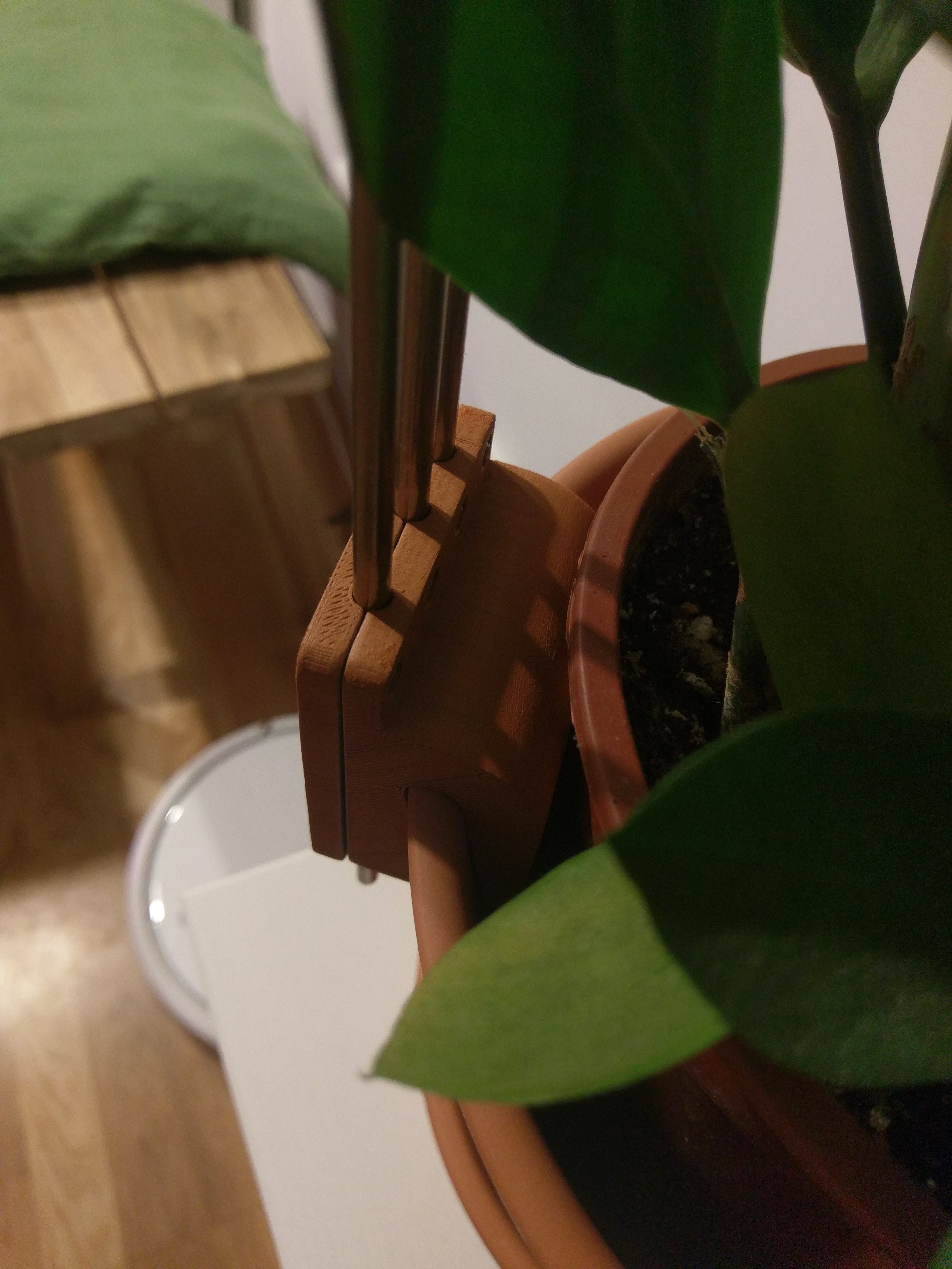
04/09/2018 at 22:21 • 0 commentsI gave spray painting a pot clamp a shot to see if giving it an effect color that matches the pot could look nice.
Here a try with terracotta spray paint. I gave it first a layer with spray filler, sanded that and then a layer of primer. I think it actually came out quite nice.![]()
![]()
-
Watering
04/07/2018 at 23:48 • 0 commentsPlant watering is probably the most solved problem of all for this project. There are probably thousand different ways to water your plants (semi) automatically.
So I wanted to integrate with a solution that is readily available and cheap.
Luckily the most readily available solution are these dripper watering sets that come with 6mm tubing which fit perfectly well into a 5mm fuse clip.
You can get a set for 12 plants at about 6€ at Aliexpress: https://www.aliexpress.com/item/1-Sets-Fog-Nozzles-irrigation-system-Portable-Misting-Automatic-Watering-10m-Garden-hose-Spray-head-with/32685122008.htmlYou can also get the cheaper orange ones where you get about 50 drippers for the same price. The grey ones are actually spraying rather than dripping.
Though that is just one part of the problem. You also need a pump, first I thought it would be more economical to use a single large pump for several plants and control water intake with a solenoid valve. Though I quickly discovered a small water pump that is readily available on ebay and aliexpress that is just 1€ more than a solenoid valve, so its a no brainer to let every plant or "system" have its dedicated pump.
You can buy one of those pumps here for ~3.40€
https://www.aliexpress.com/item/High-Quailty-Ultra-quiet-DC-12V-4-2W-240L-H-Flow-Rate-Waterproof-Brushless-Pump-Mini/32830067673.htmlThey are small enough so you can actually mount them on the metal rods as well which I will do next! For now I just put in on the floor to test my tube clipping mechanism. Here is a full video showing everything:
You don't have to put it on an extra arm of course. Here it spraying from the top, from the same the led module sits on. The fuse clips are perfectly comfortable holding larger loads, you could probably add two more light modules without any issues.
![]()
Next up is a dedicted PCB to hold the water pump vertially at the bottom of the rods to make the whole thing more self contained. No one wants a bunch of little pumps scattered around their floors... -
Test setup
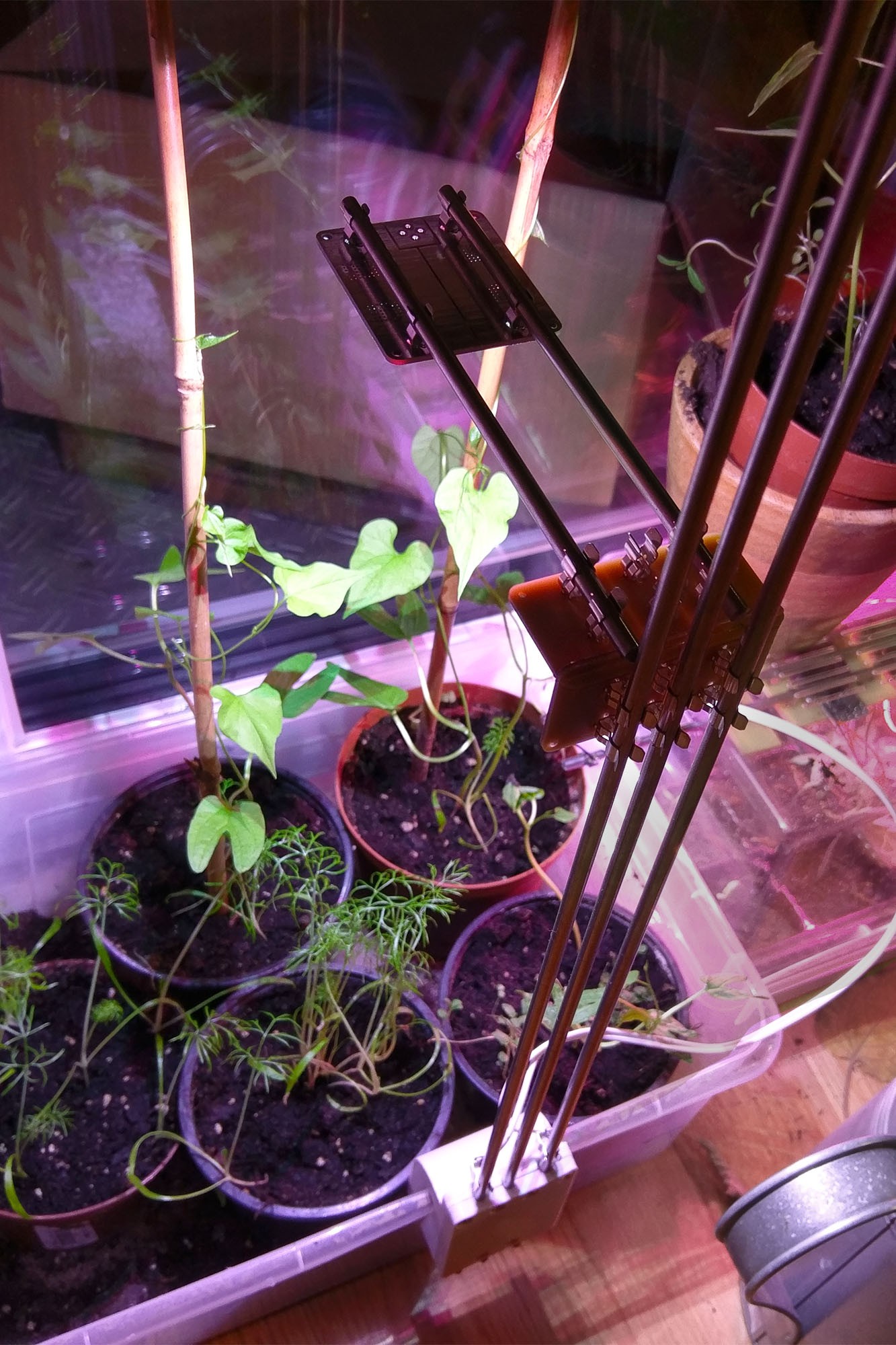
04/04/2018 at 22:11 • 0 commentsWhile the brown PCB angle and the Samla box is not exactly winning any beauty contest I'm very satisfied functionality wise. The Samla box serves as a second stage for the young plants after they grew to big for the breeding box, after that they will get their dedicated pots.
The 3D printed clamp was nicely adapting from a pottery pot to a plastic box without any adjustments to the design. It holds very tight and is able to support the 70cm long metal rods just fine.
I added the clamping mechanism of the first clamp design to the top of rods to give them more support, otherwise it was very easy to jiggle a rod around with your hands due to the long length of the rods, now they are sitting firmly in place. I will design an additonal minimal clamp similar to the one for #MoAgriS: Modular Agriculture System to give support for long rods like these. I think the design should scale well to 1.5m and longer.
The plants are enjoying the light so far. For the estehtics I think having a proper PCB with probably white soldermask (or none and just have tinned copper for an all metal look) will go a long way to improve the looks. I think an all metal surface finish could give the setup a very nice industrial kind of look. Though for the plastic parts I would stick with white or for the clamp maybe go with the color your plant pots are in. I ordered some terracotta spray paint and see how that works in conjunction with my terracotta pots.
![]()
-
Warm white full spectrum LEDs
03/28/2018 at 21:52 • 0 commentsI just discovered something very promising. So called "new full spectrum LEDs". They promise a similar good spectrum for plants but are not fully plant focused like the usualy "full spectrum LEDs" which radiate a pinkish red color which is really not something you wanna have in your home unless you really love that color.
So what I did so far is mix every full spectrum LED with a standard cool white LED.
This product now seems to combine the two in one package and just add enough green and blue to make it a comfortable light color. Right now they cost a bit more but that would be very well worth it.While the solution I have works, its not perfect, in certain light angles you get fringes of pink when the light hits the wall around the plant and you don't have a lamp shade on.
The "no harm to eyes" should not be mistaken as an actual harm to your eyes, more in the sense of, it looks really bad...
![]()
-
Plant Pot Clamp
03/26/2018 at 23:26 • 0 commentsI've been designing a parametric model in Fusion 360 (view or download) that can be easily adjusted to different plant pots. The first iteration was quite a fail. I totally disregarded the fact that plant pots are circles (well at least the vast majority) so it ended up only fitting with one of its clamps.
![]()
Not exactly as intended...
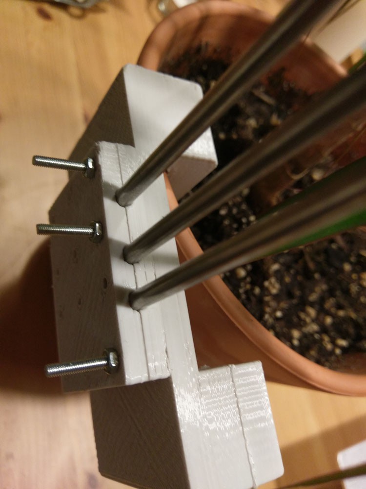
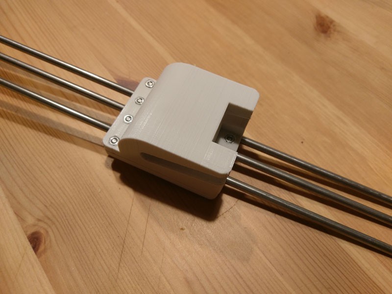
It was also very bulky which I didn't like so I scrapped that clamp and designed a new one that was more compact. I stay with the initial concepts of having two halfs that are screwed together to clamp the rods in place.
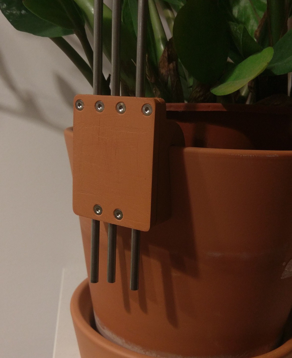
This is how the new design looks like. It fits nicely on its intended pot. I gave about 0.3mm tolerance which I think weren't necessary, having a snug fit or even undersizing it a little might be beneficial.
I messed up the dimensions for the hex nuts, they were way too small. I ended up hot pressing them with a soldering iron which worked suprisingly well.
![]()
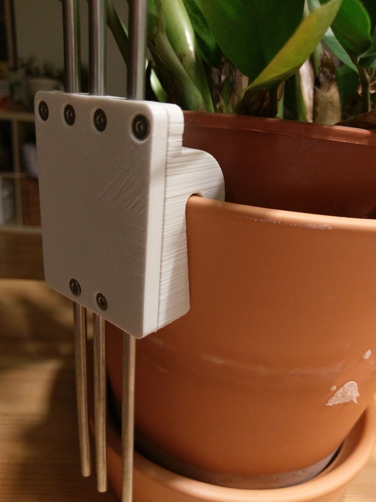
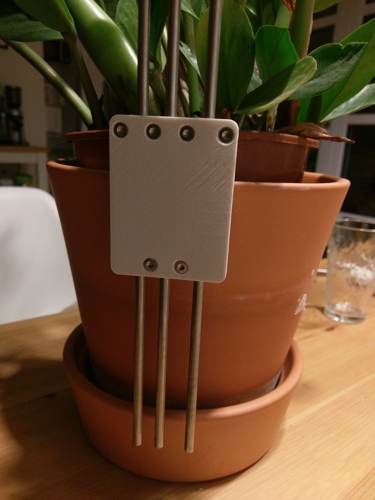
And this is how it looks on the pot (see below). I'm quite pleased with the result. It's compact but is still very strong.
The two bottom screws have two functions, first to give more strength in the case of lateral force where the plastic at the top screws might snap and second to deal with pots that have a weird shape where you may have a fat lip at the top or non linear curvatures.In that case you can choose longer scews than needed (M3x12 countersunk) and screw them in deep enough to hit the pot to give extra support in these cases.
![]()
![]()
And here a "full assembly" with angle and light attached.
![]()
MoAgriS: Modular Agriculture System
Growing food crops and other plants in small indoor spaces using established containers like regular plant pots and very little money.