 Greg Duckworth
The piezo will itself generate a small voltage spike when it is flexed. This means that the method of detection can be as simple as triggering when the returned voltage goes away from ground (assuming one side of the piezo is grounded)
This has the drawback in that it requires a dual voltage op-amp setup so that both positive and negative voltages can be properly detected. Instead I have chosen to bias one lead of the piezo at 2.5V (or so). This means that any deviation from 2.5V will trigger the circuit.
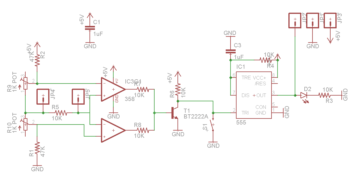
Anyway, the above design is the smallest design I could manage while still including the test switch and the LED indicator. The biasing of the piezo is achieved by the two fixed and the two variable resistors shown on the left of the schematic. The two fixed resistors basically fix the max window range to ~2.45 - ~2.55V. The variable resistors allow for trigger level adjustment to a sensitivity that is better than my multimeter can measure.
To the right of the resistors are two jumpers with a resistor between. This resistor (R5) helps the piezo voltage settle in a short amount of time so as to avoid double triggering. The two op-amps are simply used in comparator mode, one triggering if the piezo voltage is less than the lower bound and the other triggering if the piezo voltage is higher than the upper bound.
The output of the op amps is fed, via current limiting resistors, to the transistor. This acts as an inverter and ensures predictable behaviour because of the pull-up resistor (R6). The switch is also able to trigger the output to help test the probing software and to avoid machine crashes.
The 555 timer is configured as a re-triggerable pulse former. This design is all over google with explanations that are better than I would be able to manage here. The important thing is that the 555 gives a fixed length pulse out from a jittery input. The pulse length is set by the resistor and capacitor pair (R4 and C3). The values displayed give a roughly 10µS pulse length which is plenty for the interrupt on the arduino.
This circuit has shown itself to be very sensitive to vibration and touch events. It is highly sensitive to the extent that it is impossible to walk in a room with a piezo stuck (with tape) to the floor, without it triggering on each step.
I can provide eagle files if people are interested and I will answer question on the circuit if people have them.
I had the prototype boards made up by OSHPark which is an amazing service that I will definitely use again. They cost less that £3 for 3...
Discussions
Become a Hackaday.io Member
Create an account to leave a comment. Already have an account? Log In.
Has this project ever been tried on a cnc machine as a 3d probe ?
Are you sure? yes | no
Another point: The switch is included as a way of manually simulating a touch event so you can test that the CNC machine will stop before you go actually crashing a tool into anything :)
Are you sure? yes | no
It has been highlighted that it is not obvious where the piezo actuator is connected: It should be connected to JP4 and JP5. The polarity does make a difference so you may need to switch them over to achieve the highest sensitivity for your application.
Are you sure? yes | no