 Andrew Ferguson
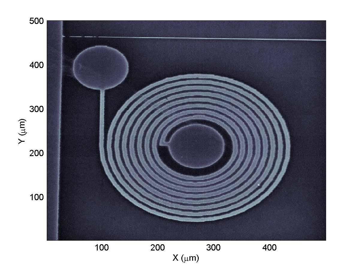
Continuing with the desktop system, we have had fun taking some more images, using the violet laser. This time the sample is a planar microwave inductor that we had lying around. As you can see the inductor has 8 turns and a track width/separation of about 10 um. The circular pads are for wire-bonding to and the lighter regions are thin-film gold. By the way, do let us know if you have any good ideas for devices to image - an old integrated circuit with relatively big feature size might be interesting.
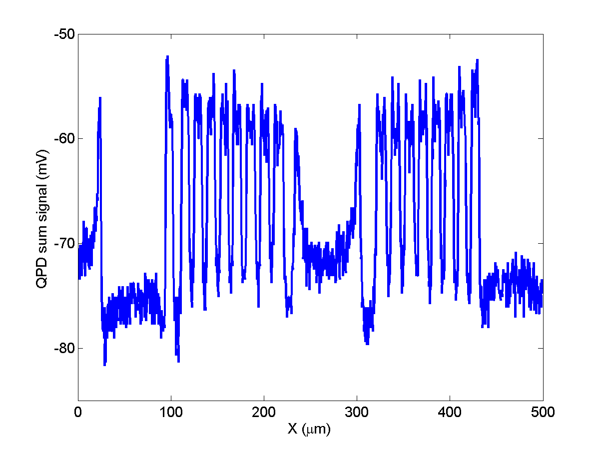
In addition to the image, here is a cross-section through it (about half way up). The risers are about 1 um and, in the future, we will use these to profile the beam and see how close to the diffraction limit we get.
Discussions
Become a Hackaday.io Member
Create an account to leave a comment. Already have an account? Log In.
Hi Thomas,
I think I saw your paper, yes. Thanks for the reminder and the link though!
And yes, the images are built up from the signal at the QPD, by locking the movement of the stage to the signal capture. Provided your stage moves more or less smoothly you can even get "higher resolution" than your minimum stepsize by oversampling.
Andreas
Are you sure? yes | no
Hey Man, just found your project. I did some hacking on this stuff previously, but my weakness was ability to work with all of the data to build up an image. Are your images built up from the QPD output? If so that's great stuff!
Have you looked at attempting any lightsheet setup using to orthogonal OPUs? The scanning laser also works perfectly for sheet illumination... the only problem is the high NA of the lenses limiting the FOV. But since you can scan the focal depth of the illumination sheet, you can build up your image similar to confocal. Just some thoughts :)
By the way, here's a paper that worked on a system similar to yours if you don't have it already: https://www.researchgate.net/publication/282457440
Are you sure? yes | no