andreas.betz
-
Hooray, we won!
07/28/2016 at 10:21 • 1 commentBluBEAM has been selected as one of the winning projects in the Hackaday prize "citizen scientist" round!
A big thank you for your support guys, and your great comments and questions.
-
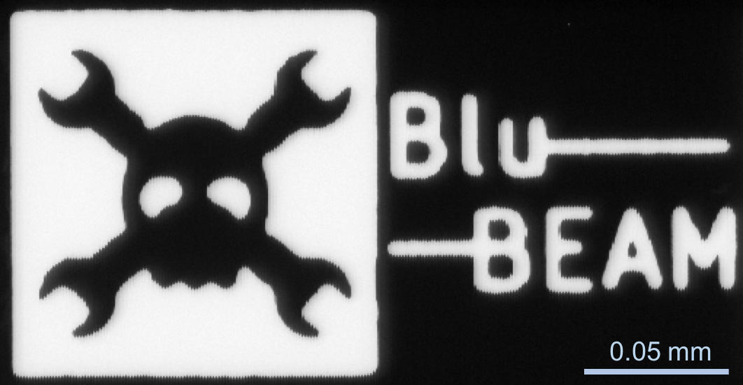
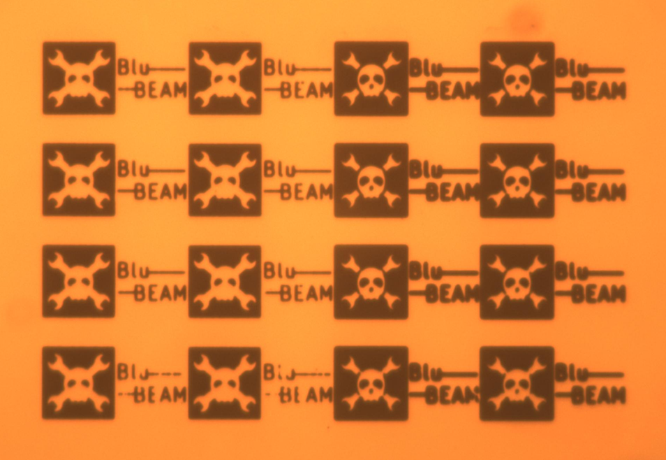
Micro Jolly Wrencher
06/24/2016 at 10:59 • 1 commentSerious things have happened in our country (the U.K.) overnight, so we thought we would cheer ourselves up by imaging a lithographically fabricated familiar figure. The Jolly Wrencher was patterned with direct write laser lithography, which can reach a resolution of better that 1 um, and of course it is similarly imaged with our scanning laser beam, with similar resolution. The total width of the Wrencher field is 125 um, which is just less than the minimum track width you can order from OSH Park (150 um).
It is pretty small, enjoy!
![]()
And here is a more standard microscopy image (using a x5 objective), showing the full pattern that we fabricated. The metal film that has been patterned is gold (100 nm) with a chromium adhesion layer (10 nm) to a polished sapphire substrate.
![]()
-
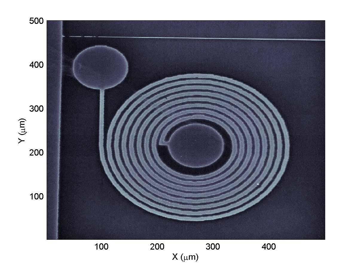
Images: a spiral inductor
06/15/2016 at 12:33 • 2 commentsContinuing with the desktop system, we have had fun taking some more images, using the violet laser. This time the sample is a planar microwave inductor that we had lying around. As you can see the inductor has 8 turns and a track width/separation of about 10 um. The circular pads are for wire-bonding to and the lighter regions are thin-film gold. By the way, do let us know if you have any good ideas for devices to image - an old integrated circuit with relatively big feature size might be interesting.
![]()
In addition to the image, here is a cross-section through it (about half way up). The risers are about 1 um and, in the future, we will use these to profile the beam and see how close to the diffraction limit we get.
![]()
-
First image! Sub-micron resolution!
06/14/2016 at 19:42 • 2 commentsWith focusing and stage movement in place, it was time to have a go at imaging something.
So without further ado, I give you our first BluBEAM confocal micrograph!![]()
What is it though? Well, I'm not too sure myself, but it's some kind of old prototype transistor fabricated by the guys at the Microelectronics lab in Cambridge, UK. Black regions are definitely a metal layer, created by e-beam lithography.
Anyway, the great news we get from this image is that we have a sub-micron resolution of about 680nm!
Let's see how far we can get with this now... -
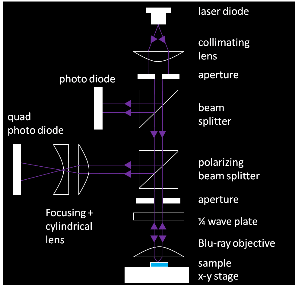
Update: System overview & focusing
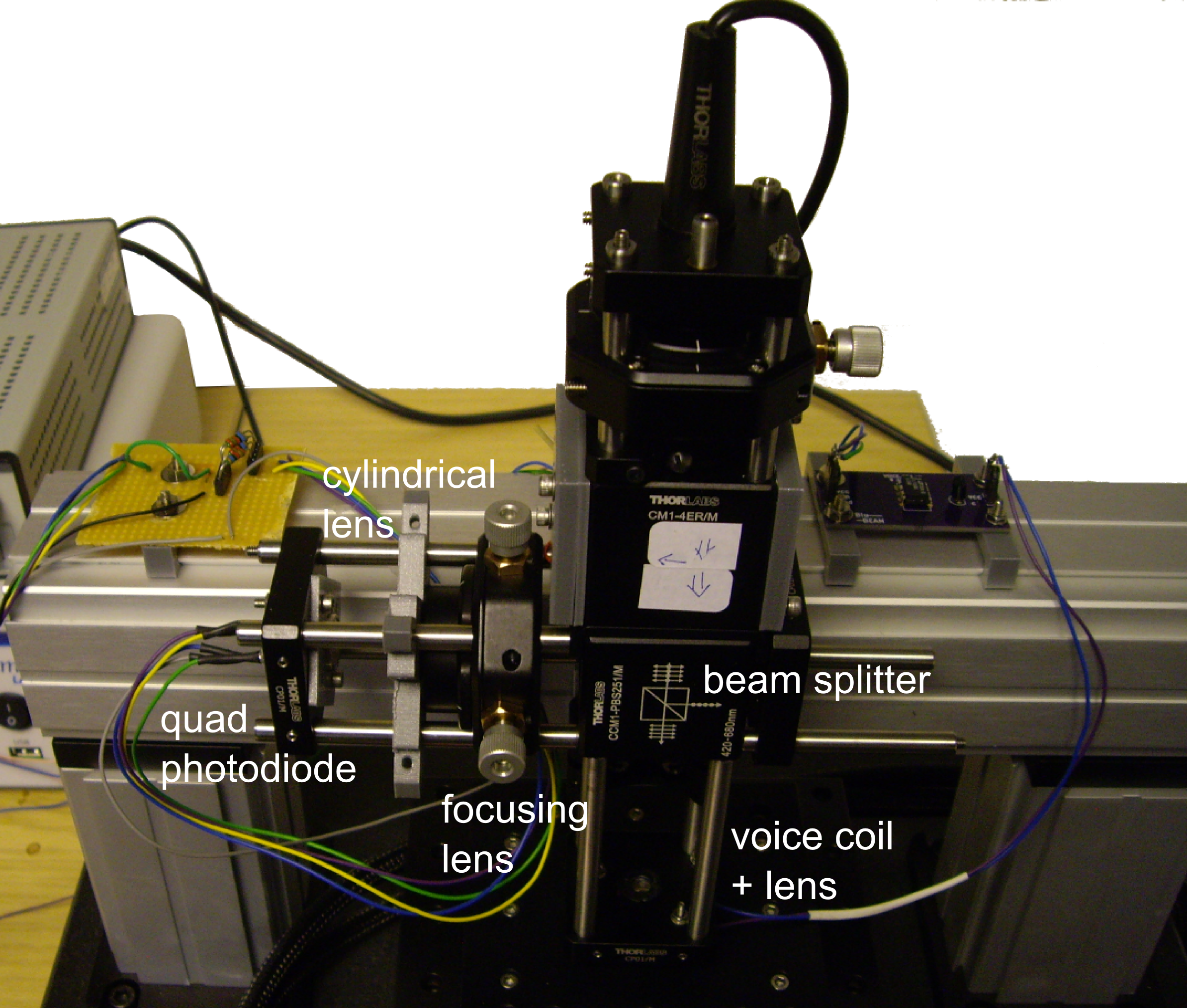
06/14/2016 at 08:43 • 0 commentsFurther to the last post a little while ago, here's schematic overview of the system as it stands right now:
![]()
We have two photo diodes now, a single one to measure the laser output power via a 50/50 beam splitter, and the quad photo diode for the astigmatic focusing. A second, polarizing beam splitter plus a quarter wave plate allows us to only receive light coming back up from the sample under the objective in the quad PD.
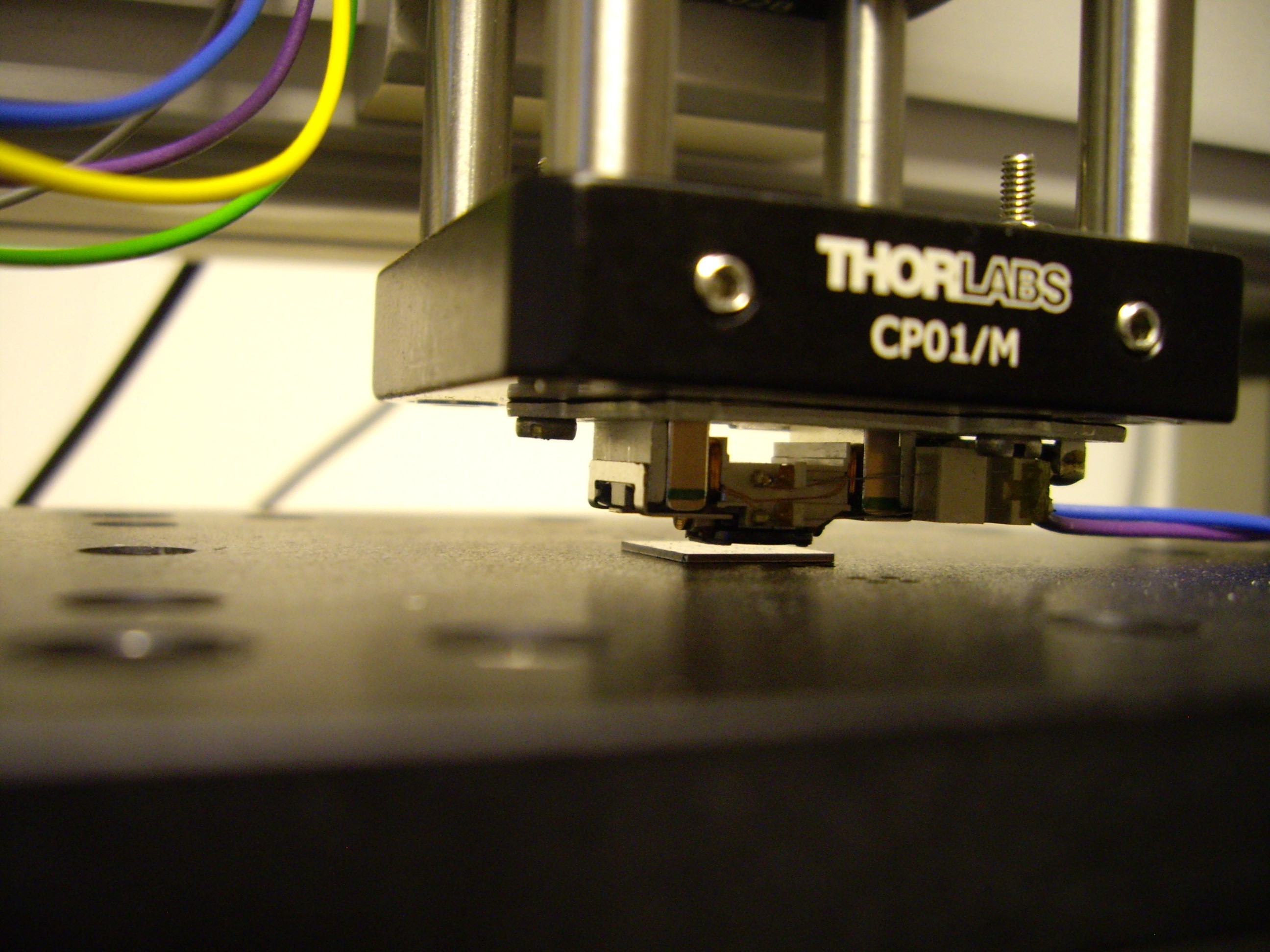
The objective is still the voice coil assembly salvaged from a PS3 drive.
![]() It allows us to have a dynamic focus range of several mm, paired with μm precision, all controlled by an DC voltage input to the VC driver board. The lens in the assembly is also pretty good, with a numerical aperture NA = 0.85. NA is important especially in microscopy, as it sets the resolving power: the smallest detail that can be resolved by the lens, and thus the microscope, is proportional to λ/2NA, where λ is the wavelength. So, in theory we should be able to separate details that are as little as 240nm apart. In theory...
It allows us to have a dynamic focus range of several mm, paired with μm precision, all controlled by an DC voltage input to the VC driver board. The lens in the assembly is also pretty good, with a numerical aperture NA = 0.85. NA is important especially in microscopy, as it sets the resolving power: the smallest detail that can be resolved by the lens, and thus the microscope, is proportional to λ/2NA, where λ is the wavelength. So, in theory we should be able to separate details that are as little as 240nm apart. In theory...We also have a high precision x-y-stage in the setup now. It can displace the sample under the objective at sub- μm precision.
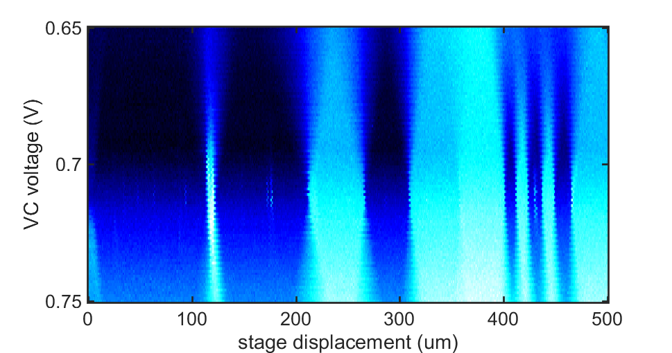
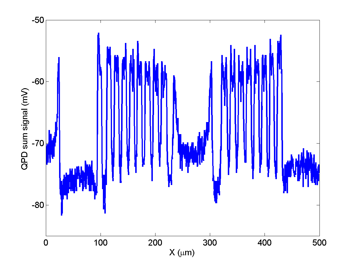
From tests Andrew did in his amazing Michelson interferometer project, we know the amount of z-displacement per unit current (linear with VC voltage) and can now calibrate the focal depth of our setup: about 1 μm. We get this information by repeatedly scanning across a steep edge and stepping the focus (i.e. the VC voltage) for each line.![]()
We could of course also use that procedure to focus on the sample, but the astigmatic approach makes it so much faster: All we need is to acquire the quad PD signal as function of VC displacement, as shown below.
![]()
-
Read-head mock-up
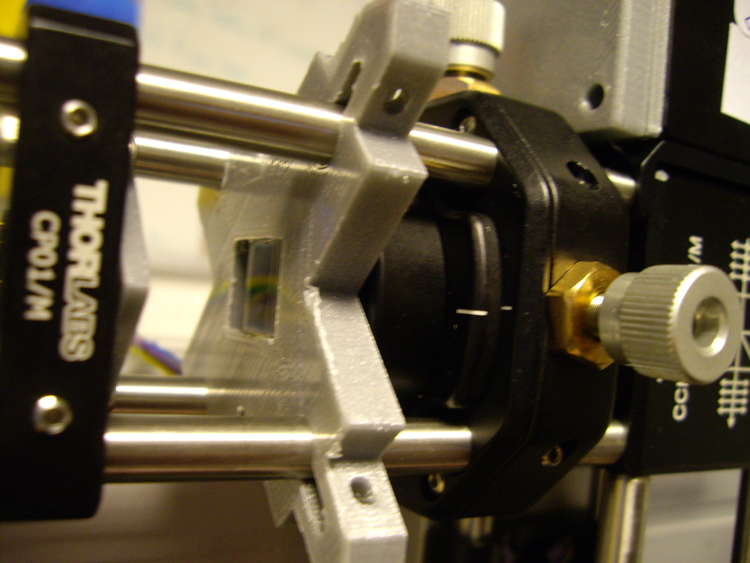
02/29/2016 at 11:05 • 0 commentsIt's been a while now since my last log and here's why: We have been busy building a mock-up of the read-head from larger, conventional optical components.
The PS3 read-head is great as it got everything we need neatly packed into a small form factor. However, because it's such a well engineered piece of tech, the margins for things like head - sample misalignment are small, very small. In fact that was our biggest challenge with it so far, to get the returning beam to hit the built-in quad-photodiode. A quick and dirty comparison of the quad-diode with diffraction grating showed that it's only a few tens of micrometers in size. Which means that a misalignment of less than a degree already brings us way off the little sensor.We still wanted to check that we can focus using the cylindrical lens approach, so we built this mock-up:
![]()
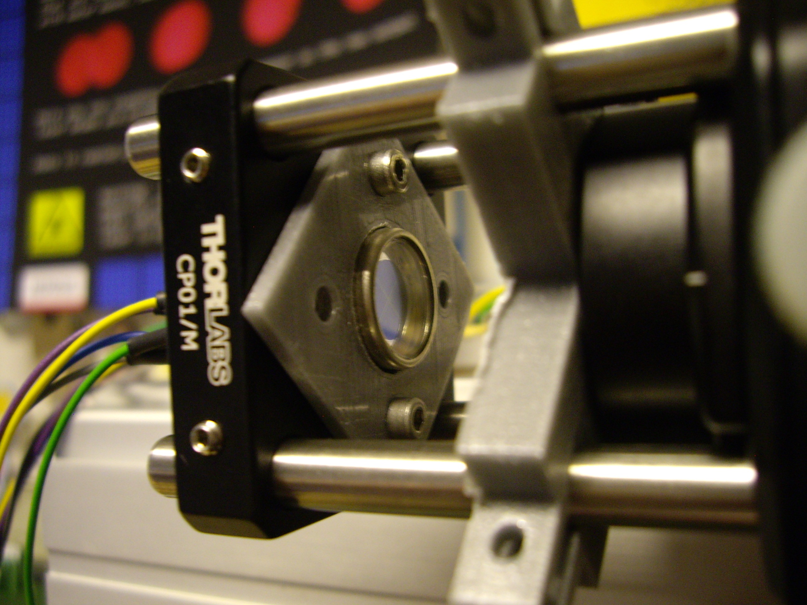
It works in exactly the same way, bringing a collimated blue laser beam through the voice coil + lens assembly from the PS3-head, diverting the returning beam with a beam splitter, and finally acquiring the signal with a quad photodiode.
![]()
The voice coil is controlled by our custom made driver PCB, with the set-point voltage coming from a PC DAQ card. We use the same DAQ for the quad-diode later.
We also have another focusing and a cylindrical lens between the beam splitter and detector, to give us the elliptical-circular-elliptical shape for focusing.
![]()
The quad-diode itself is pretty big and the last focusing lens is mounted on a translation state, which together allows us to compensate for misalignment in the setup.
![]()
So let's see whether we can now compensate for misalignment and get the elliptical-circular-elliptical data we're looking for.
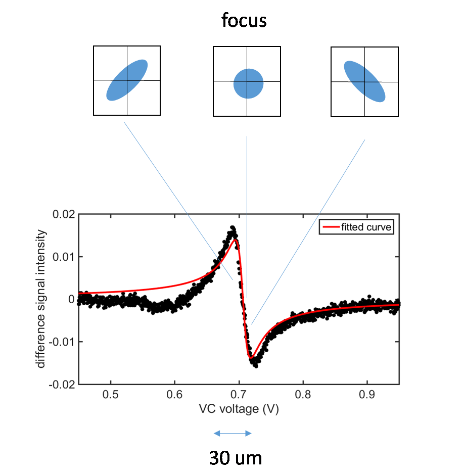
Here's what we do to get there:The quad-diode is oriented in such a way that the two elliptical out of focus beams will cover two opposite quadrants each. So first of all we adjust the system in such a way that all signals from all four quadrants (A,B,C,D) are equal when we move the voice coil through the focal point.
![]()
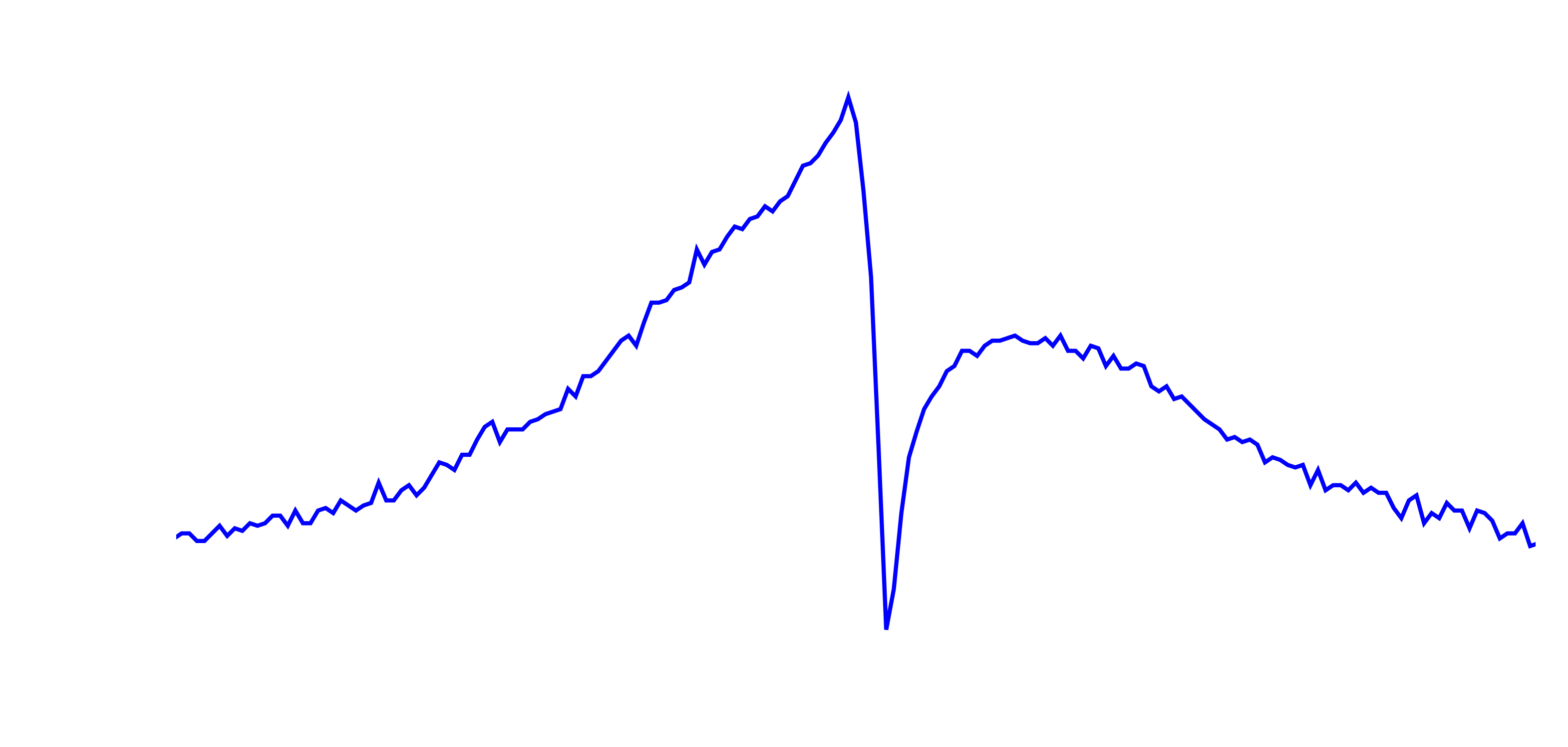
You can already kind of guess where that focal point is from the above, but the easiest way of finding the "circle of least confusion" (where the cylindrical lens doesn't distort the beam in any direction) is to compute the so called "S-curve" by calculating (A+C) - (B+D), where A & C, and B & D are opposite quadrants. The circle of least confusion is then at 0, because that's where all quadrants are hit by exactly the same intensity.
![]()
So what we see here (from left to right) is first very little signal because we're way out of focus, then more and more light from one elliptical orientiation. The middle part is what gives this the name S-curve, when we go from one ellipsoid through the circle of least confusion to the other elliptical beam. The photodiode is also picking up a good amount of stray light, which means that the circle isn't at 0 here, but at some offset.
All in all I'm very happy with these results. We're not using the read-head itself, but with the mock-up we are able to get the auto-focus principle to work and we circumvent the alignment problem by introducing an additional translation element. -
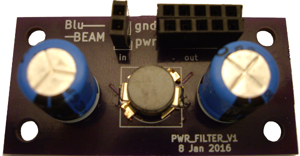
power line filter
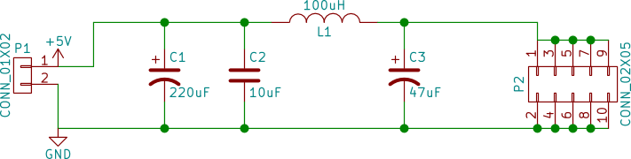
02/11/2016 at 18:02 • 0 commentsThe last board I made is a filter for the power supply feeding the previous boards. As with any electrical project it's vital that we have a clean power supply, and in particular we want to avoid burning our lasers.
I'm using mostly big through hole components here, following this schematic:
![]()
And here is the finished board:
![]()
The big question of course now is whether it actually filters and how much. I don't have access to a network analyzer that goes to very low frequencies, so here's what we're going to do instead:
Make a function generator send a 1V peak-to-peak sine wave with a 1V offset (so we don't annoy the electrolytic capacitors too much) into port P1. Then look at the output at P2 with a scope reading off Vpp at the frequency we set on the function generator.![]()
OK, so our filter blocks pretty much everything above a few tens of Hz with the -3dB point at around 10Hz! Promising!
-
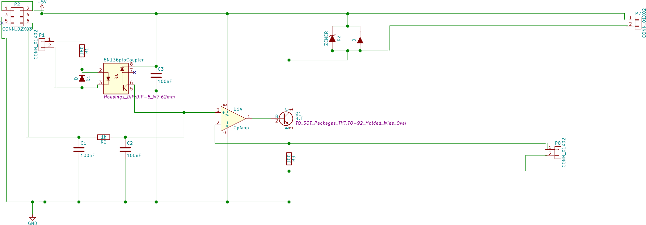
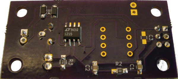
Laser driver - PCB & test
02/10/2016 at 17:23 • 1 commentOK, now that we have control over the voice coil and hence the focus, we need also to be able to control the laser and its power.
We are going to achieve this pretty much in the same way as we did with the voice coil. After all the core principle is the same: supply a defined current (now to the laser diode), and to make things easier get it linearized.
However, there are also a few small differences we need/want to account for. First of all, we won't need quite as much current this time. The lasers work at around 20 - 40 mA, compared to the 100+ mA of the voice coil. More important still is the fact that the laser diodes are quite fragile. So in addition to the general current driver circuit we need to include a protection circuit that shorts out the laser if there's too much current or a reverse current. This can be easily achieved with a Zener diode plus a normal diode in parallel with the laser.
![]()
The rest of the circuit is as I said, pretty much the same as the voice coil one, except for the values of components. We are e.g. using a faster op-amp (LT1215) and higher capacitances for the set-point filtering.
There is another part of the circuit that is obviously different: the opto-coupler part. I am not going to implement it just yet, but it's purpose is simply to allow us to quickly switch the laser off if needs be by grounding the non-inverting pin of the op-amp.
And this is what the end result looks like.
![]()
![]()
The PCB also includes a port to measure the voltage across the 33Ohm resistor (between the BJT and ground), which gives us this plot of current vs setpoint voltage V_set:
![]()
Again, all nice and linear and we can easily reach the 20 - 40 mA we need for the lasers. We could even change the 33Ohm for say 100Ohm if we wanted to increase precision.
-
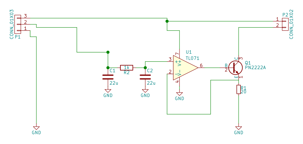
Voice coil driver -- PCB & test
02/04/2016 at 11:54 • 1 commentOK, now that we have our PCBs from OSH Park we can get on with populating it and finally checking that we get the linearized current we need for the voice coil.
So first off, here is the schematic again.
![]()
For the resistors and capacitors we chose surface mount components (size 0805 for easy hand soldering); the op-amp and bipolar transistor are through hole. Note also that instead of a 1kOhm resistor I'm now using 20 Ohms to allow for sufficient current. Depending on how precisely we need to drive the voice coil and what resolution we can get from the set point voltage source (most likely 0-5V), we may have to rethink that value.
Since the voice coil driver doesn't need to be particularly fast, but should run off a single 5V supply, we're using a Linear Technology LT1006 here. The transistor is a Fairchild PN2222A.
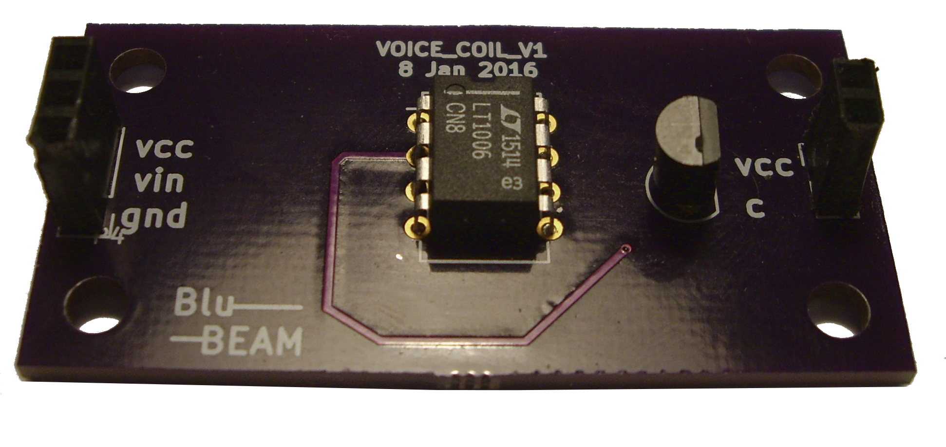
Here's the finished board. All SMD components are on the back, by the way.
![]()
As you can see from the schematic, Vcc will be a 5V supply and Vin sets the laser current.
So let's give that a go then:
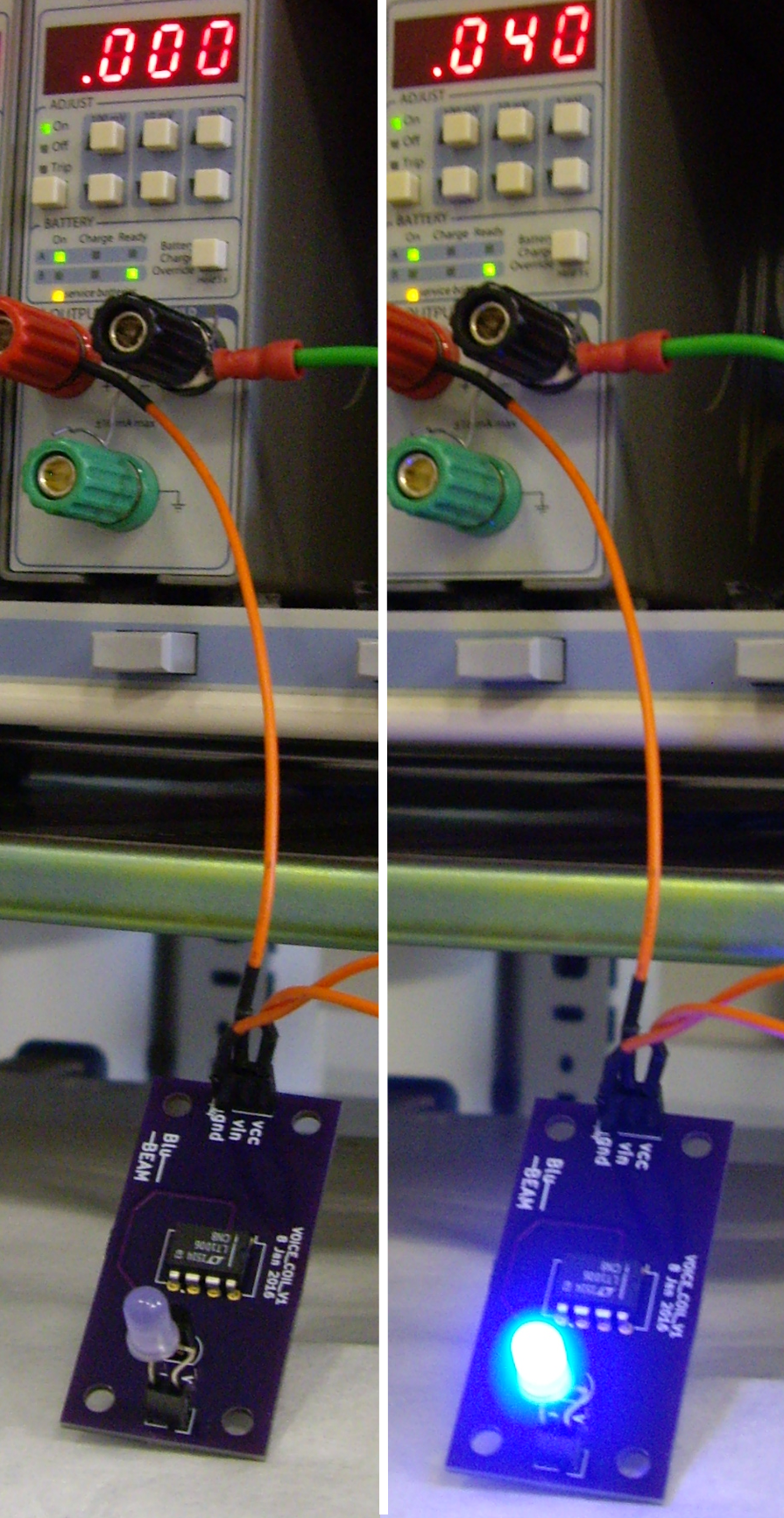
First of all, I'm going to test the board and circuit by putting in an LED instead of the voice coil (so much easier to see... :), supplying 5V Vcc and a set voltage on Vin.
![]()
Works nicely. Vin values below 40mV obviously light the LED less brightly.
Next, I need to check
a) what current we get as a function of voltage on the BJT base (Vin),
and
b) whether that current is linear now. That's the whole point of having an op-amp in the board...
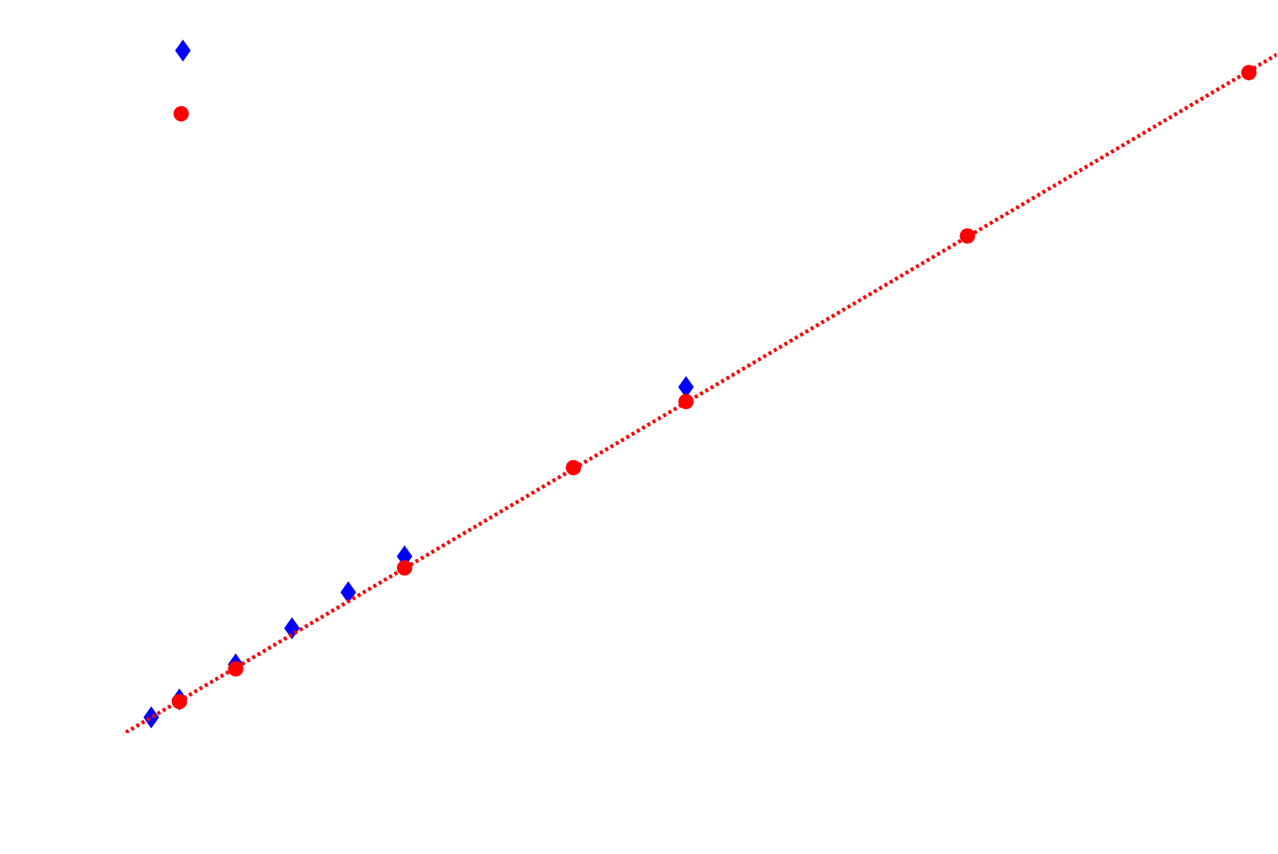
So let's switch the LED for a resistor and measure the voltage Vr across it vs BJT base voltage Vin. Vcc is 5V as it also supplies the opamp. Ohm's law then gives us the current through the resistor Ir = Vr/R.
![]()
I've tested the current output with two different resistors, a 1k and a 9.7 Ohm. The latter is a much closer match to the actual resistance of a voice coil. As you can see from the graph above we've achieved what we needed: the output is linear with set point Vin, and our range is OK too, as Vin = +/- 2V will result in about +/- 100mA.
-
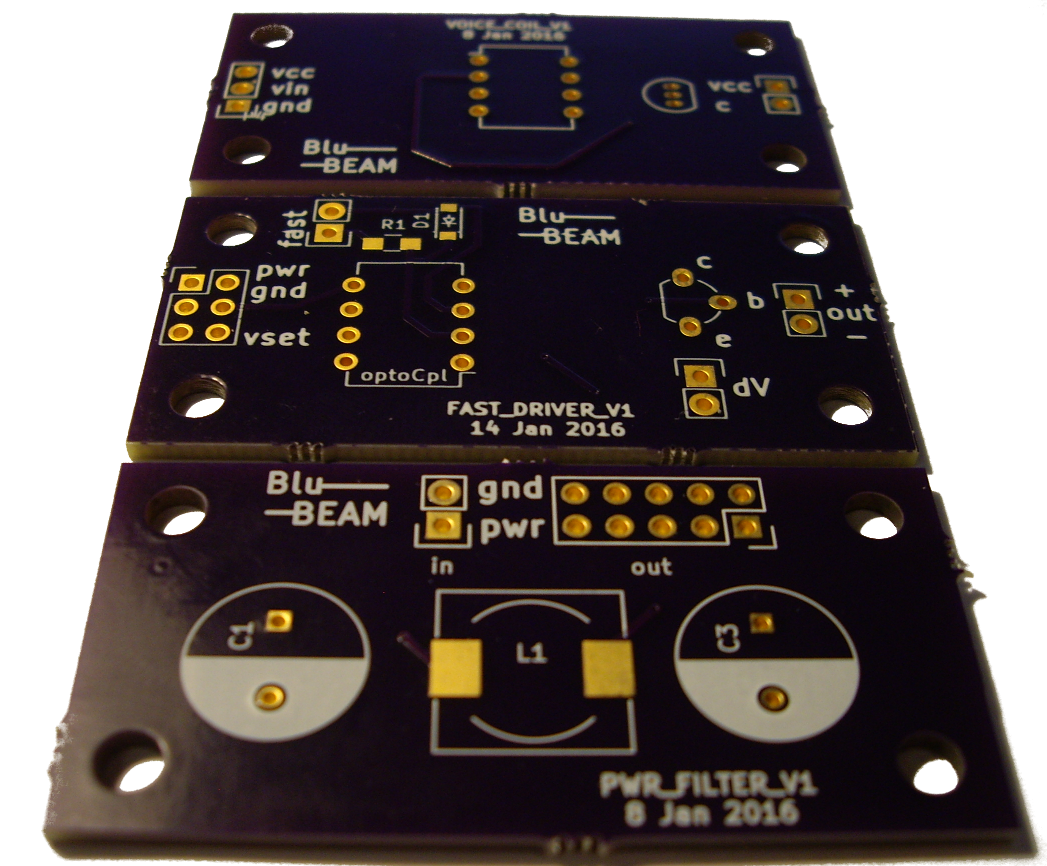
PCBs!
02/04/2016 at 11:15 • 0 commentsHooray, our PCBs have arrived!
![]()
All in OSH purple and gold plated contacts.
Now it's just a matter of getting components soldered on and we can test them.
BluBEAM - a scanning laser microscope
Imaging at micrometer resolution using a Blu-ray drive
 It allows us to have a dynamic focus range of several mm, paired with μm precision, all controlled by an DC voltage input to the