Blecky
-
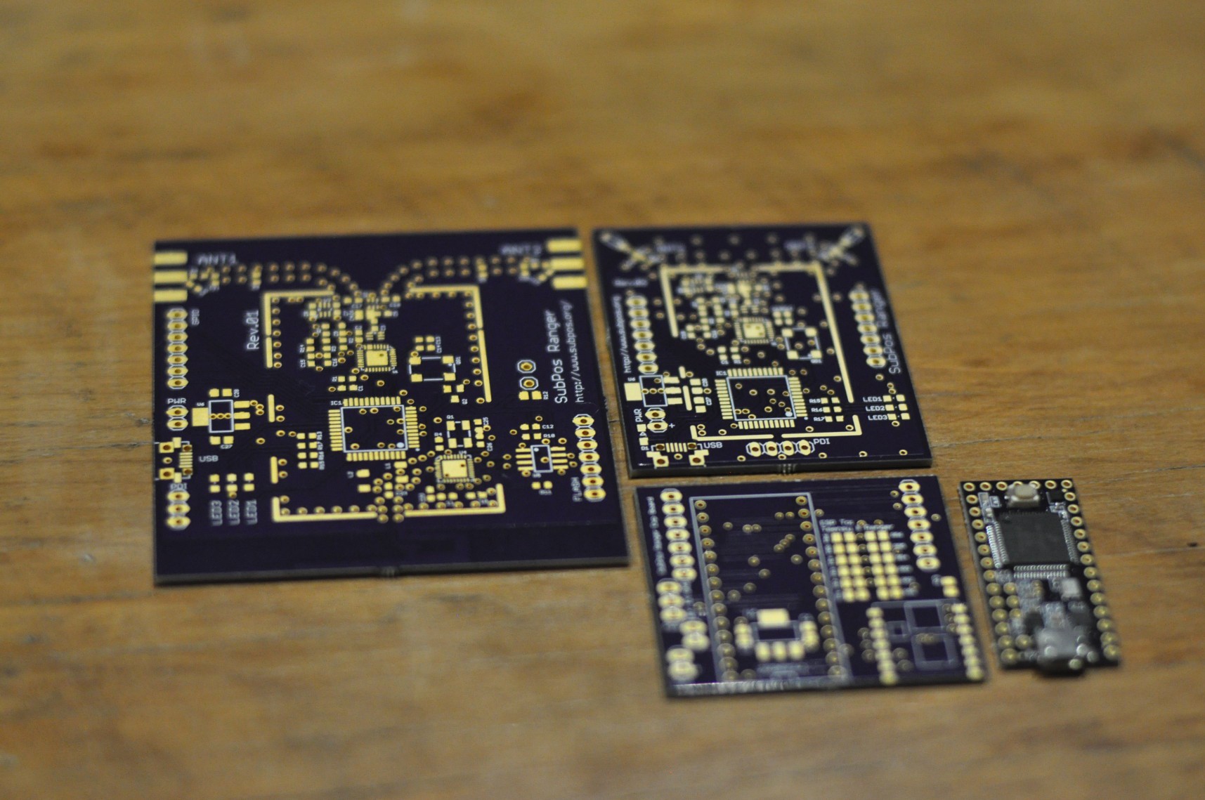
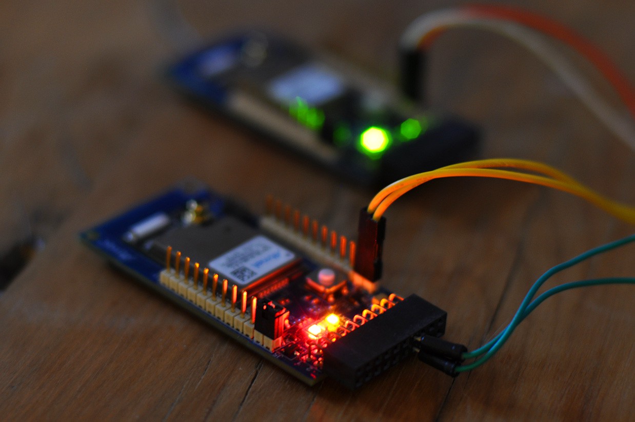
Rev.02 Board Arrived
05/23/2016 at 09:32 • 0 commentsAfter a nice long wait in Australia Post, the Rev.02 boards have finally arrived (on the right):
![]()
I should have these made up in the next day or so.
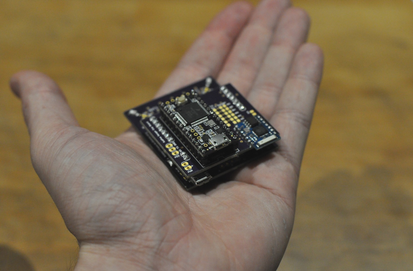
Client board assembly:
![]()
While it seems odd to have two USB ports on the client, the USB port at the bottom is used for firmware programming of the Ranging module. While it might not be used often, the cost to have different board manufacturing setups outweighs the cost of the extra part, so I've left it in.
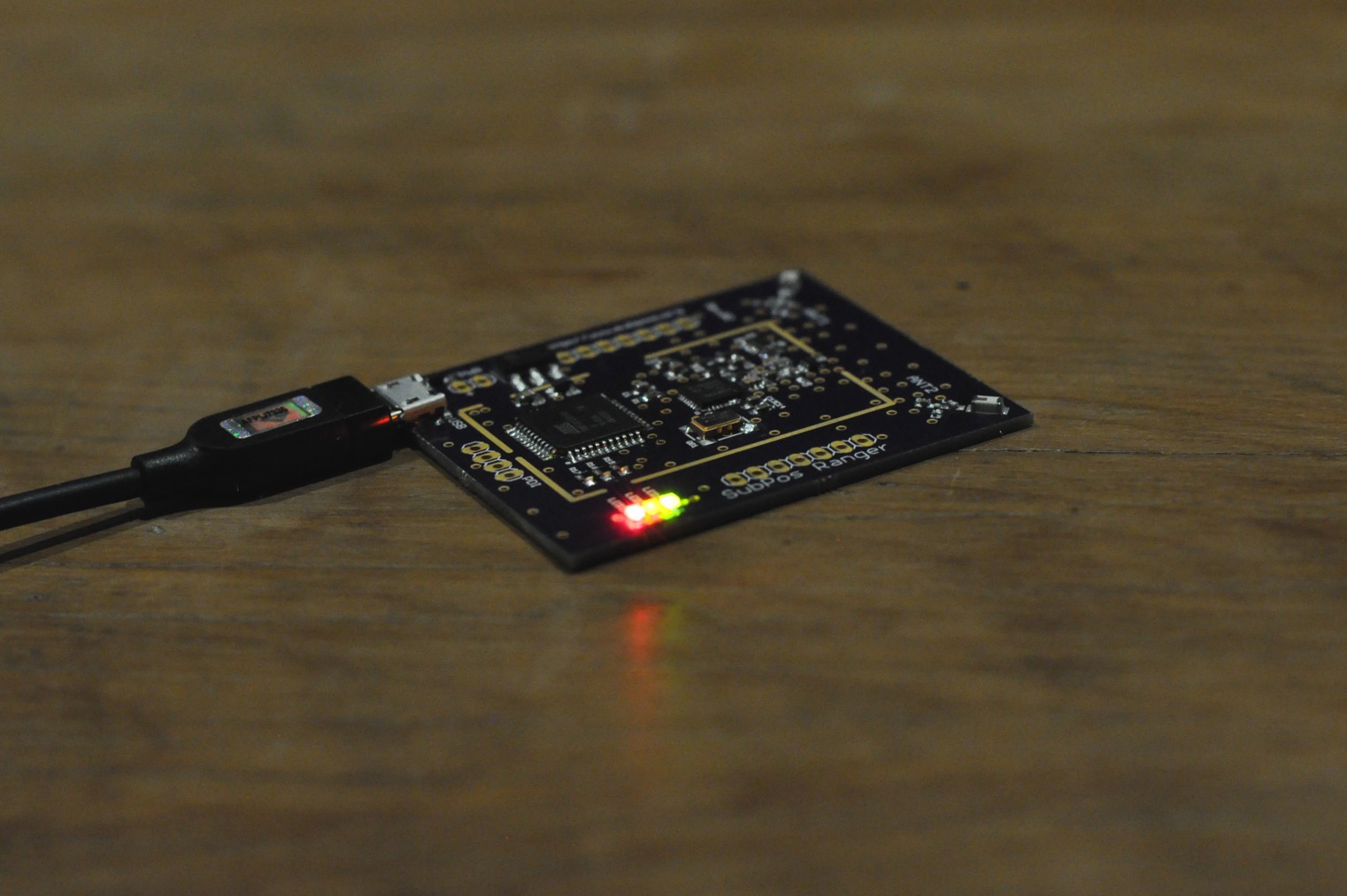
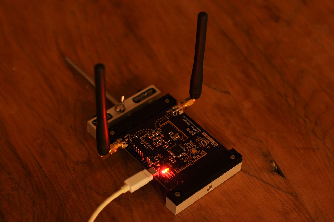
Edit: It lives!
![]()
-
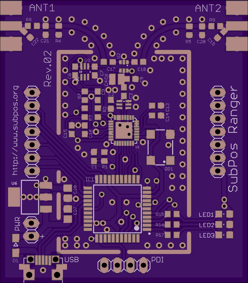
Ranger and Client Design
04/25/2016 at 13:13 • 0 commentsI have changed the design of the client and ranger boards slightly to reduce manufacturing overhead. The new client and node Ranger boards will be identical, and the client will have a expansion board to perform trilateration on a Teensy3.2 module (as well as an optional Wi-Fi module). The Nodes will also use the same expansion board with only a Wi-Fi module populated to enable standards support. This sort of setup is also more flexible and could enable different applications to be developed (like tracking a client, rather than a client getting its position).
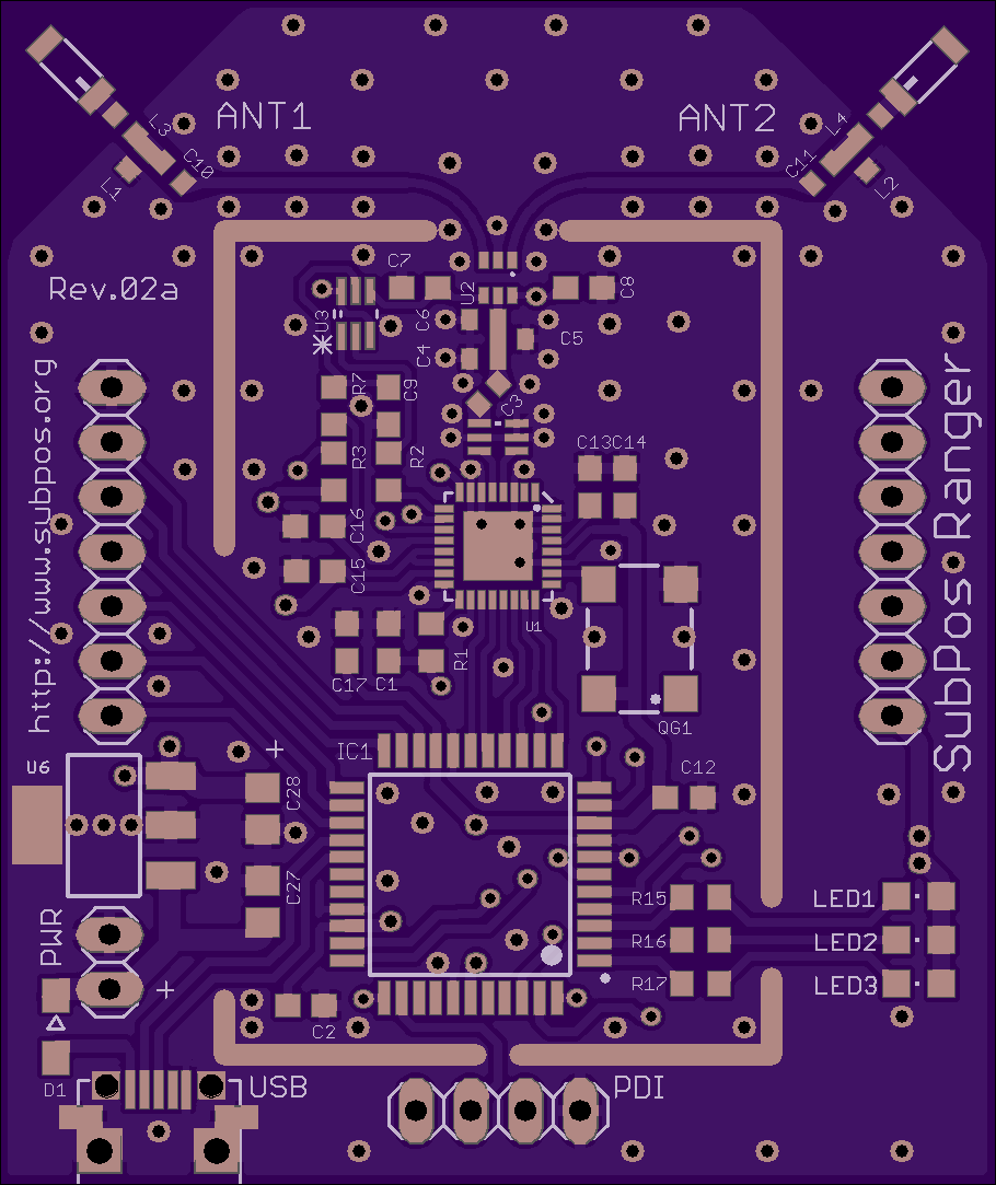
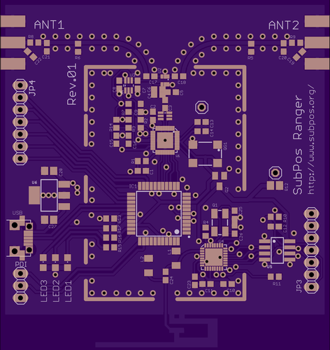
The Ranger board is only 46x54 mm, so it's reasonably small.
Here is a picture of the Ranger board:
![]()
Each board will load the same firmware, however a small solder bridge at the back will determine which operating mode it supports (client or node).
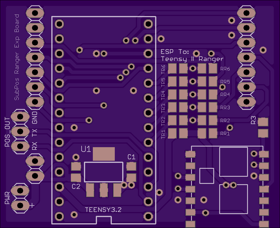
Here is the expansion board (with bridges depending on the operational configuration):
![]()
The expansion board is designed to be easily modified or upgraded if you decide to change it later on.
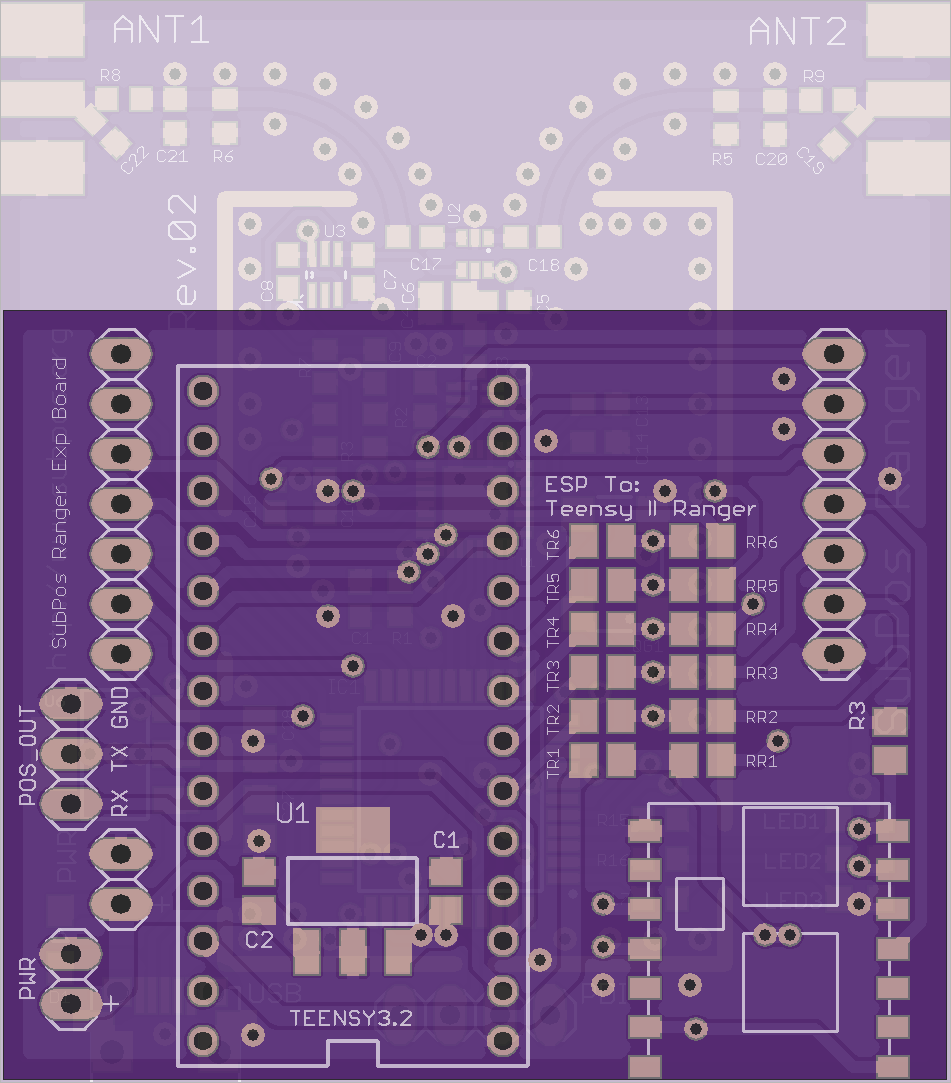
The board will fit (optionally top or bottom mounted) like so:
![]()
I'm currently researching suitable alternate ceramic antenna designs, so the design might change slightly, but the overall functionality will remain the same.
Edit: Now with an updated antenna design:
![]()
-
Small Update
04/24/2016 at 15:24 • 0 commentsJust got the last of the demo code up and running. I've also decided to design the system to be more modular.
Essentially the Ranger Nodes will be made without Wi-Fi on board, which reduces cost and size. When operating without Wi-Fi (no standards support), the client needs to know the locations of all the Nodes.
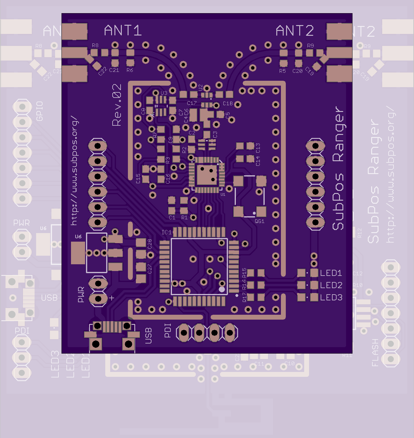
Here is a pic of the new Ranger Node design overlaying the older design:
![]()
The headers on each side there allow a Wi-Fi breakout board to plug into the bottom, if Wi-Fi and/or SubPos Standard support is desired.
-
Ranger Verification
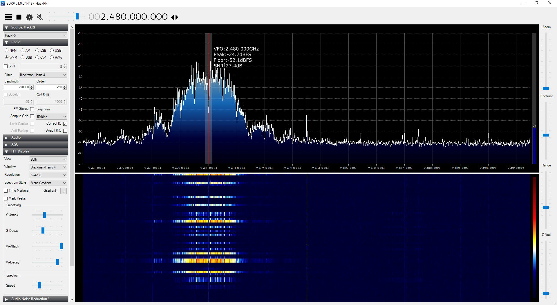
04/07/2016 at 11:53 • 0 commentsBack from holidays, I decided to do some rudimentary verification that the RF design on the boards is actually correct (being closely related to the reference design, this should be somewhat in the ballpark). The 802.15.4 radios are currently set to channel 24 which sits on 2.480GHz.
Looking at the spectrum graph with a HackRF, we get the following:
![]()
That's almost bang on. Further verification will be required, but at least it can be shown that there is nothing too funky going on with the current design.
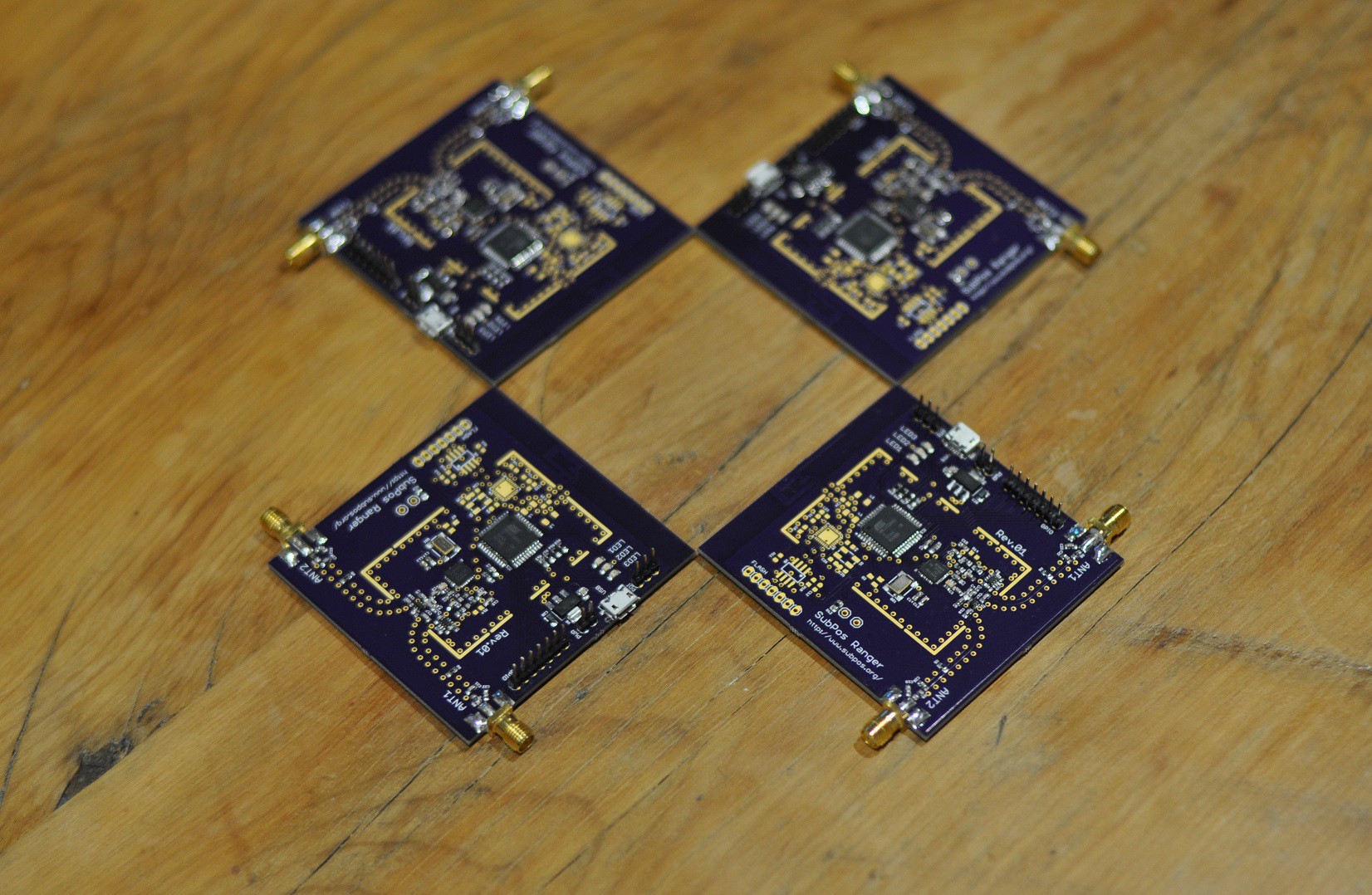
In addition, here is a glamour shot of all the boards made up:
![]()
I have also developed the code on the receiver to work with the SubPos standard (get the nodes and position, then perform ranging as per the flowchart in this post), so things are coming together. I just have to optimise it to work with multiple Rangers at once as there are some speed and ranging issues. Once that is done there will be a big demo update.
Edit:
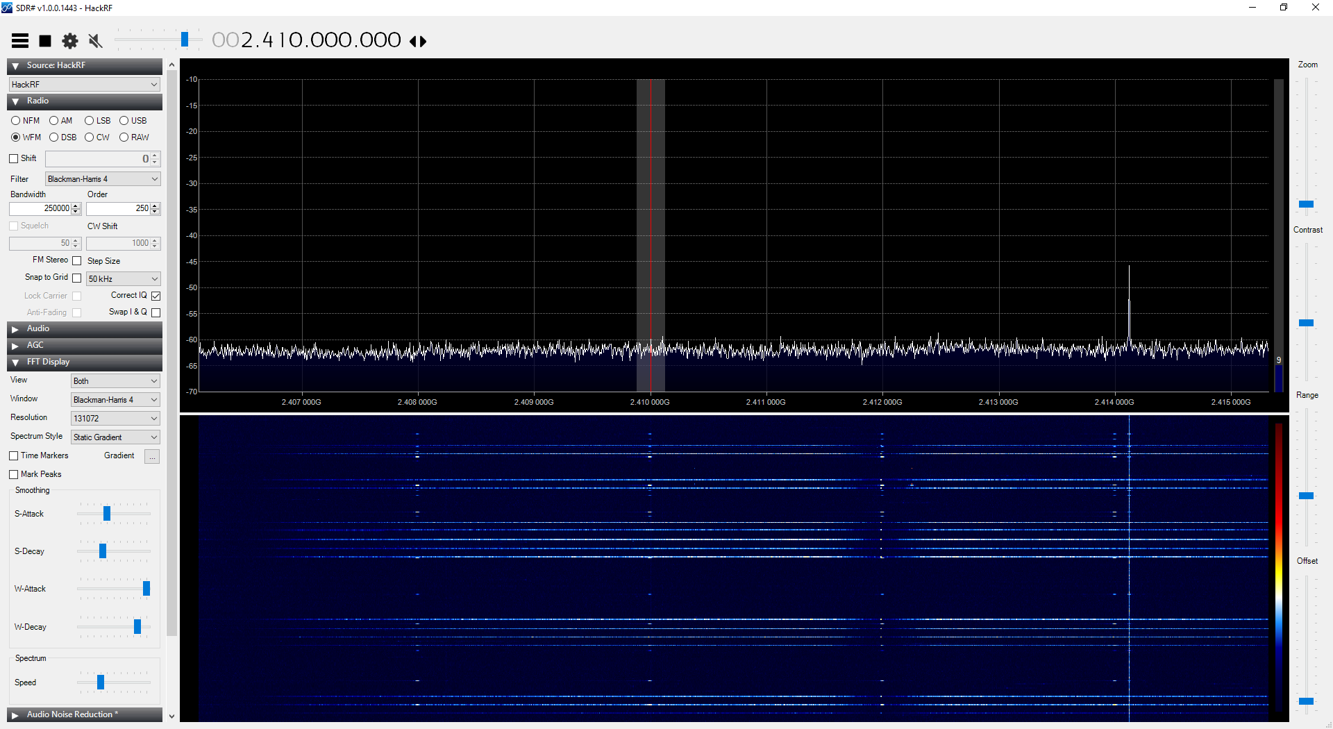
As a bonus, here is the spectral plot of the AT86RF233 phase measurements that the default Atmel ranging libraries are performing (the main method in which it performs its distance calculations; I am currently working on altering this ranging method). The ranger is set to span these measurements from 2408Mhz to 2414Mhz with 2MHz intervals. You can see these quite clearly:
![]()
-
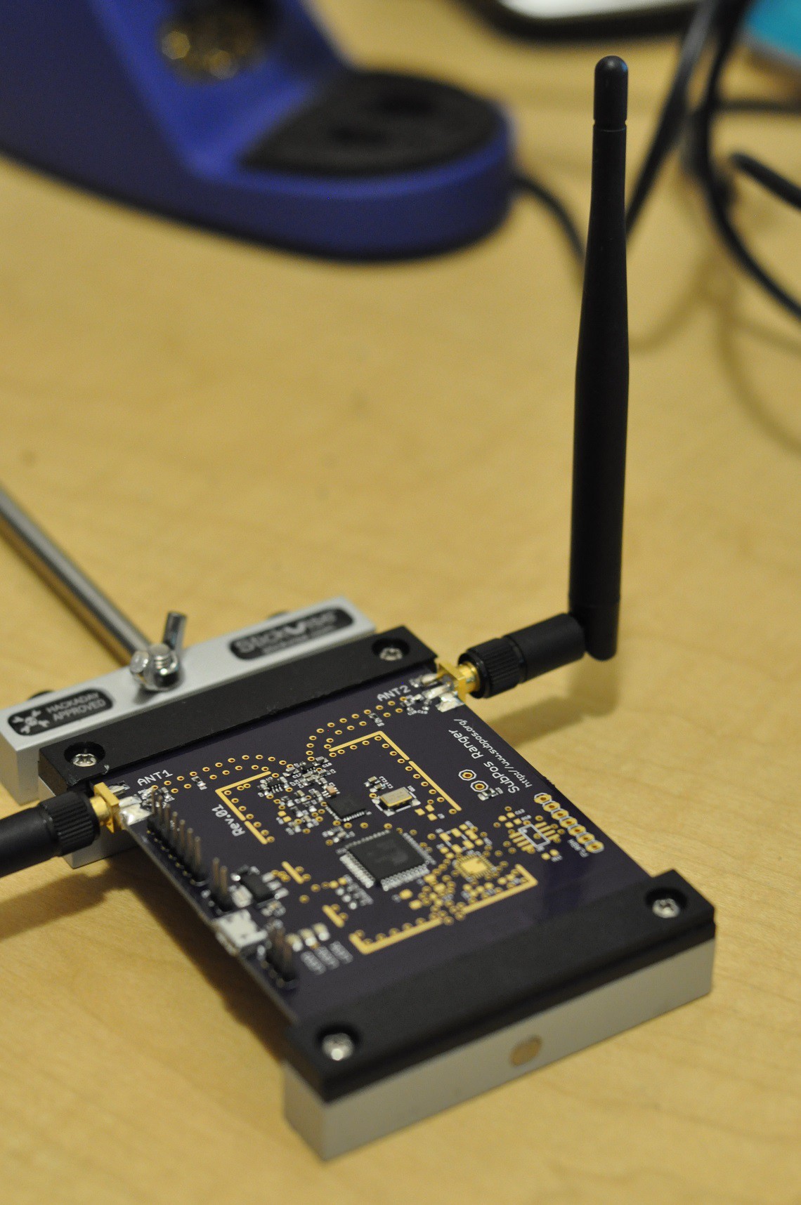
First Ranger Built
03/05/2016 at 13:22 • 1 comment![]()
Now just to get it running and tested.
Edit: It lives, albeit after a few issues getting the existing ranging code to run on an MCU with half the RAM and newer architecture (turns out static libraries for avrxmega6 don't like to compile for avrxmega7):
![]()
-
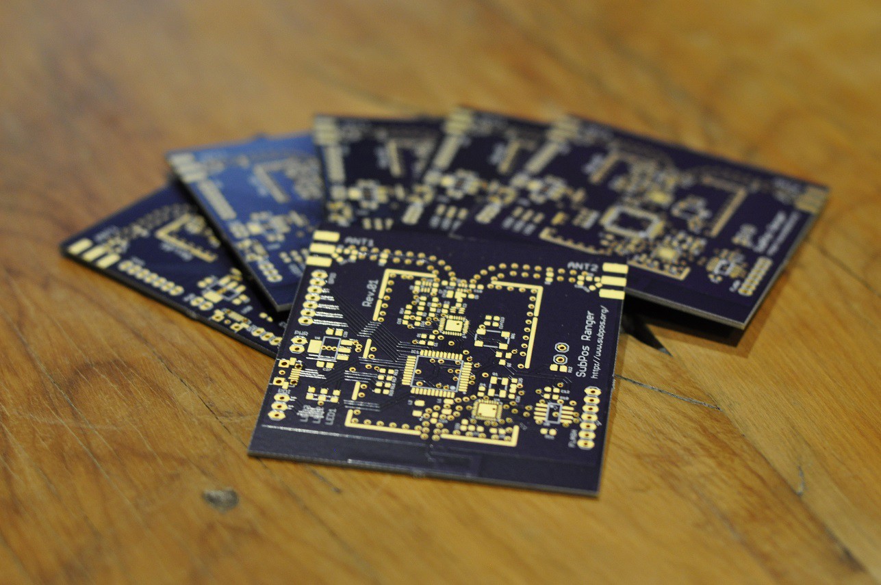
PCBs Arrived
03/03/2016 at 09:06 • 0 commentsThe Ranger PCBs have arrived!
![]()
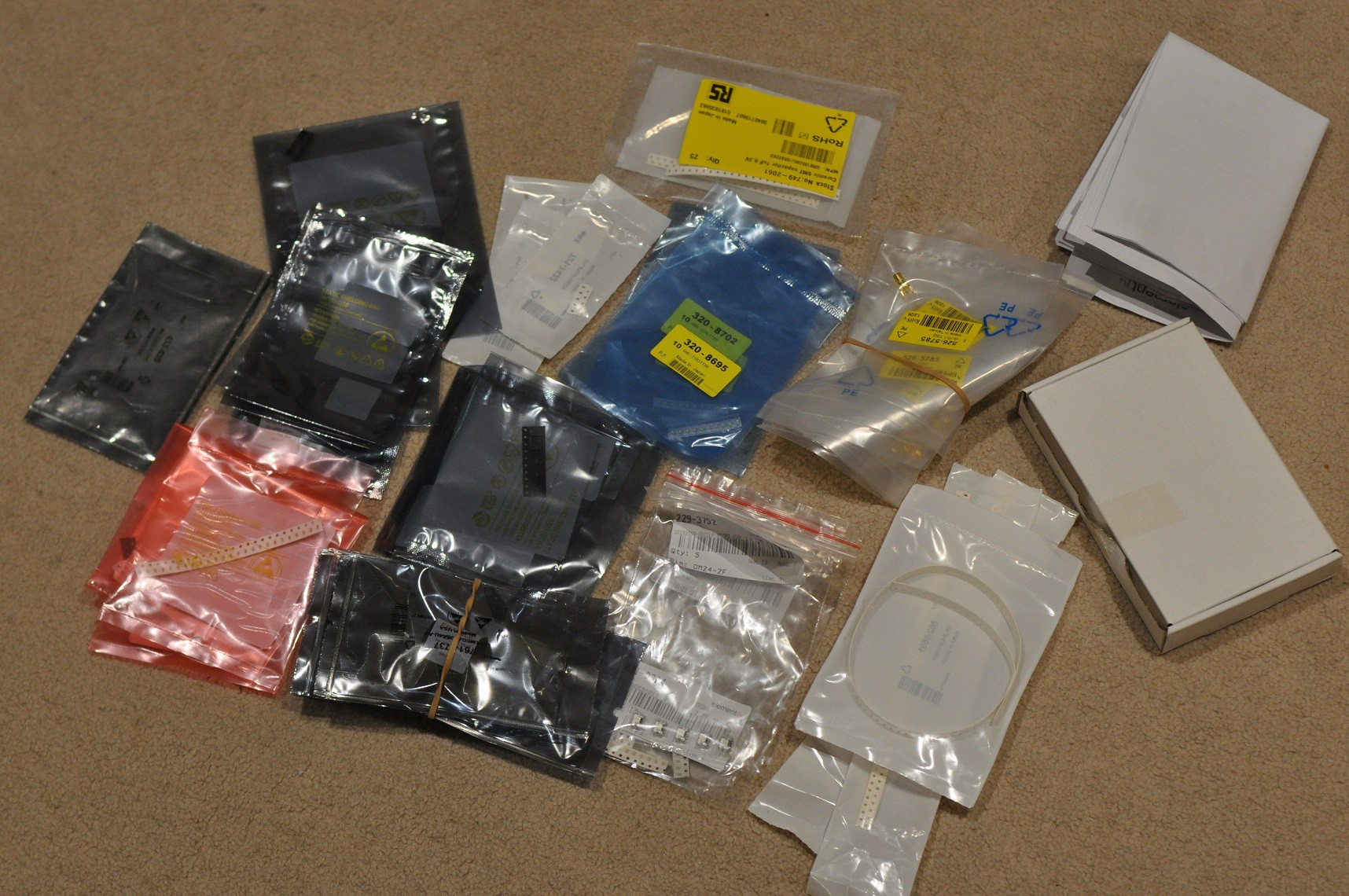
And I have a wonderful bag-o-parts ready to populate the boards:
![]()
Now just to solder some VQFNs by hand.......
-
Ranging Node Design Teaser
02/10/2016 at 13:30 • 0 commentsHere is what the prototype SubPos Ranger Node looks like:
![]()
-
How Extended Ranging Works With SubPos
01/23/2016 at 13:17 • 0 commentsThe expansion boards also support the addition of an ESP8266 module if you would like to enable Wi-Fi for you to connect to a multitude of devices such as your smartphone. The Wi-Fi module can be used to transmit data to a local server if you are using the Ranger Board for other purposes, such as motion detection, or using it as a Zigbee to Wi-Fi gateway.
One expansion board without Wi-Fi is included to convert a Ranger board to a client when you back the positioning system reward (and add a Teensy), however if you would like to support Wi-Fi on the Ranger Boards configured as a node, you can order additional expansion boards and the ESP8266 (ESP03) modules separately.
The positioning software libraries will also support the SubPos Wi-Fi Positioning System standard, when an ESP8266 Wi-Fi module with appropriate firmware is attached to both the client and nodes. The regular version of the SubPos Ranger Positioning System only supports up to 16 nodes, the standards supported version (when you add a Wi-Fi module) supports virtually unlimited nodes.
![]()
The different Ranger Board configurations.
By modifying the Application ID and utilising additional bits in the application reserved section of the coded beacon frame, SubPos can be used to implement additional features such as more accurate ranging, while still remaining completely dataless.
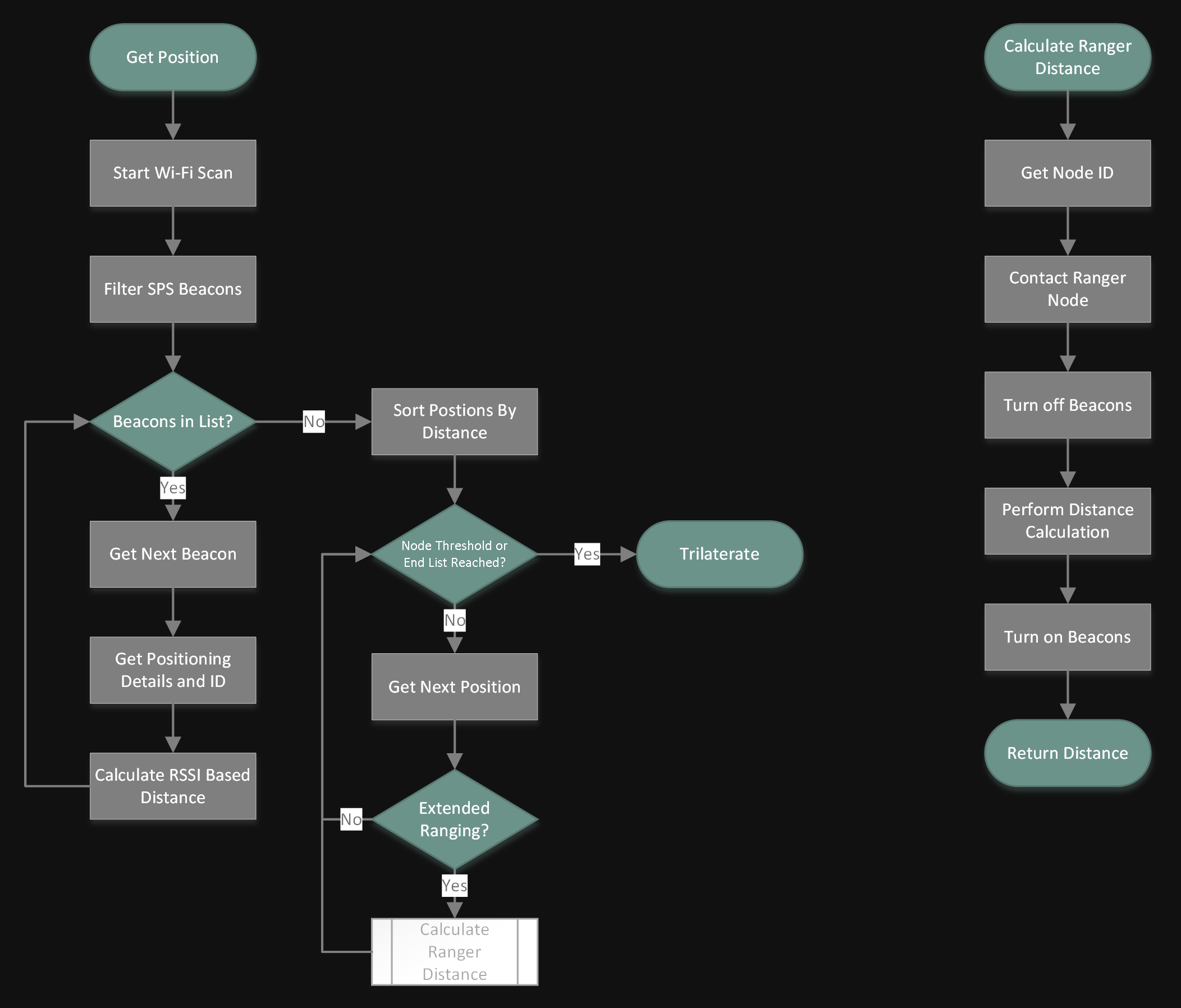
Generally it is up to the application developer to then implement this functionality as they see fit. With respect to the SubPos Ranger, this additional feature is a ranging system that performs more accurate distance measurements. The following flowchart shows how the Ranger client supports this functionality:
![]()
The node threshold in this instance is a limit to the number of nodes to range from.
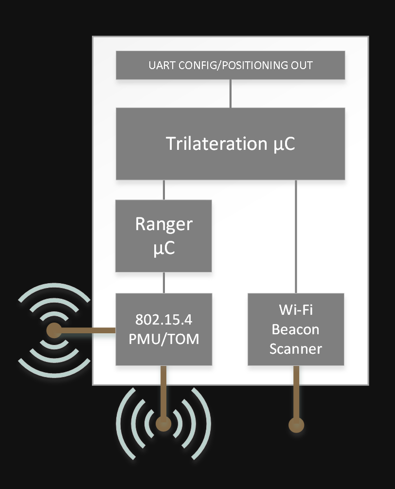
The SubPos Ranger hardware supports the SubPos standard by adding a Wi-Fi scanner and receiver to the ranging system:
Ranging Client
![]()
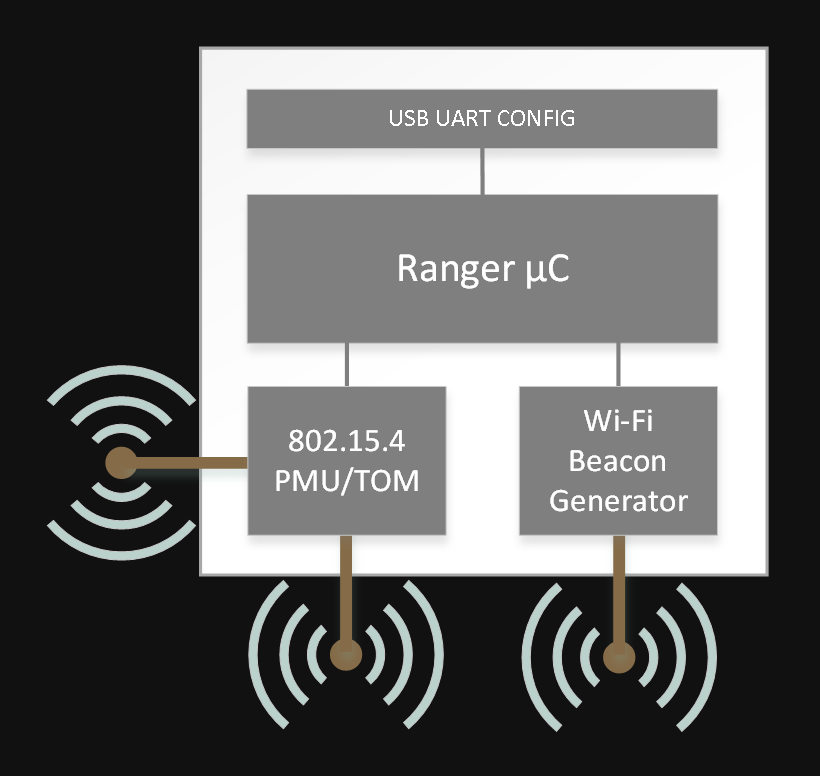
Ranging Node
![]()
While the use of the standard is optional with the Ranger system, it vastly decreases the setup time when adding additional clients to the system as they will obtain configuration from the visible nodes.
-
Ranging Demo
01/23/2016 at 11:34 • 1 commentHere is a demo of the ranging toolbox working an unmodified Atmel ZigBit module:
The firmware is the stock toolkit code (with mods to allow it to work on the ZigBit) with antenna diversity disabled (since there is only one antenna). More work is to be done, but the initial results look more than promising.
-
Ranging Working
01/19/2016 at 07:36 • 1 commentI've finally managed to rework the Atmel RTB Evaluation Application (http://www.atmel.com/tools/REB233SMAD-EK.aspx?tab=documents) to run on the ATxmega256A3U and AT86RF233 Zigbit Module (~$30), rather than having to purchase the expensive REB233SMAD-EK.
With this rework I can now start developing an extensible addon for SubPos to get additional, more accurate (+-10cm) ranging for better distance calculation.
This addon will not work with existing infrastructure or smartphones and will require a specialised receiver. However, I also have SubPos and trilateration code working on a Teensy 3.2 that this ranging module will feed into to allow it to be attached to autonomous devices for navigation indoors.
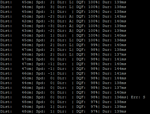
Actual output from two Zigbit modules with a single antenna:
![]()
I'll have a demo of the ranging operating shortly.
![]()
SubPos Ranger
The SubPos Ranger allows you to accurately measure distance or obtain your position indoors for all hobbyist robotics applications.