-
PFC Revision
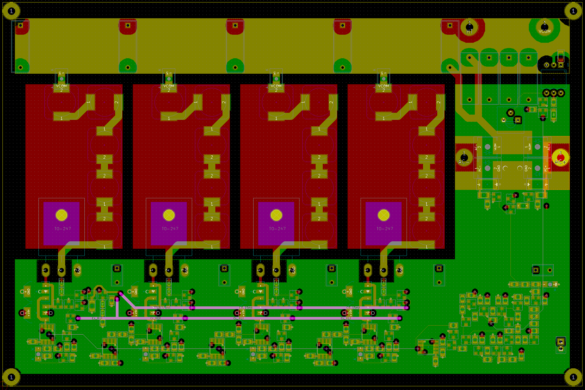
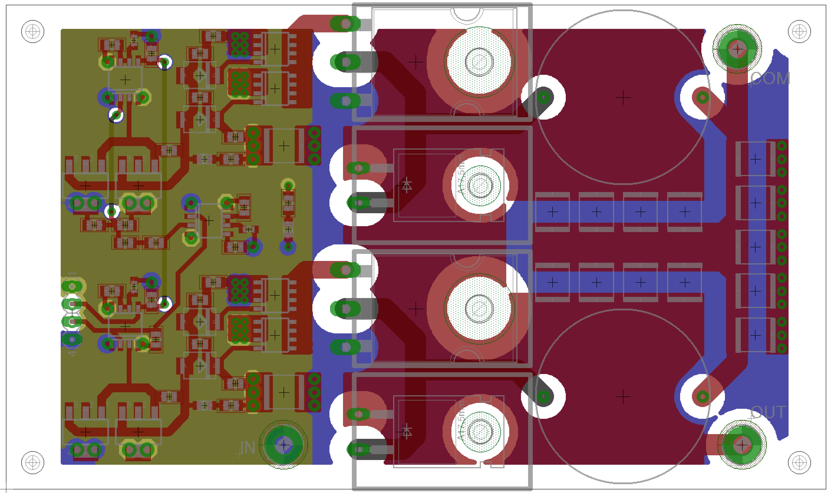
11/26/2016 at 04:24 • 0 commentsFinally getting back to this project after quite an absence. Currently working on getting the design of the 2kV power chain completed. Also taking the time to learn KiCad. A screen shot of the PFC board is included below. New PFC design boasts 400V @ 2.5A output with 220VAC input. Input EMI filter and output 8800uF capacitor bank are off-board. The switching frequency is 100kHz, and the circuit utilizes polyphase switching to minimize HF ripple and noise. Loose output voltage regulation is achieved through cycle-skipping, which preserves both the high power factor and the high efficiency of the PFC: 95% @ 1kW, 91% @ 250W. The design does not require discrete heat-sinks and uses steady airflow to maintain optimal temperature.
![]()
The 15V power plane is hidden in the image, but it has the same footprint as the ground plane. (green L-shaped layer)
-
Earlier Work
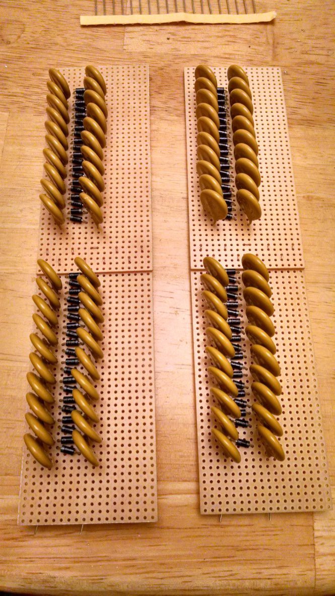
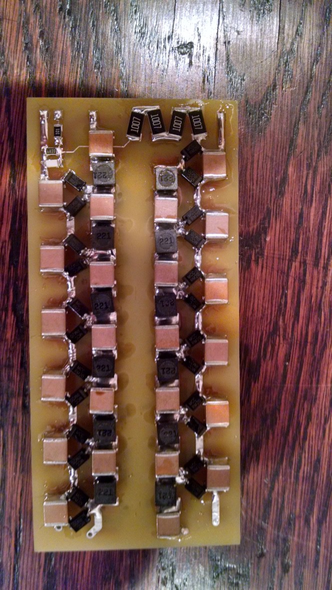
01/26/2016 at 16:08 • 0 commentsI found some photos of previous multiplier prototypes I built last year. The Image on the left is the very first set which were a 20-stage negative multiplier and a 20-stage positive multiplier. They produced several microamps at +/- 26kV and used a electronic ballast as the input source. The image on the right is the first resonant multiplier board. The board includes a resistor voltage divider and was designed to be oil immersed and produced a few hundred microamps at +/- 40kV using the same ballast as input.
![]()
![]()
-
PFC Module Revision
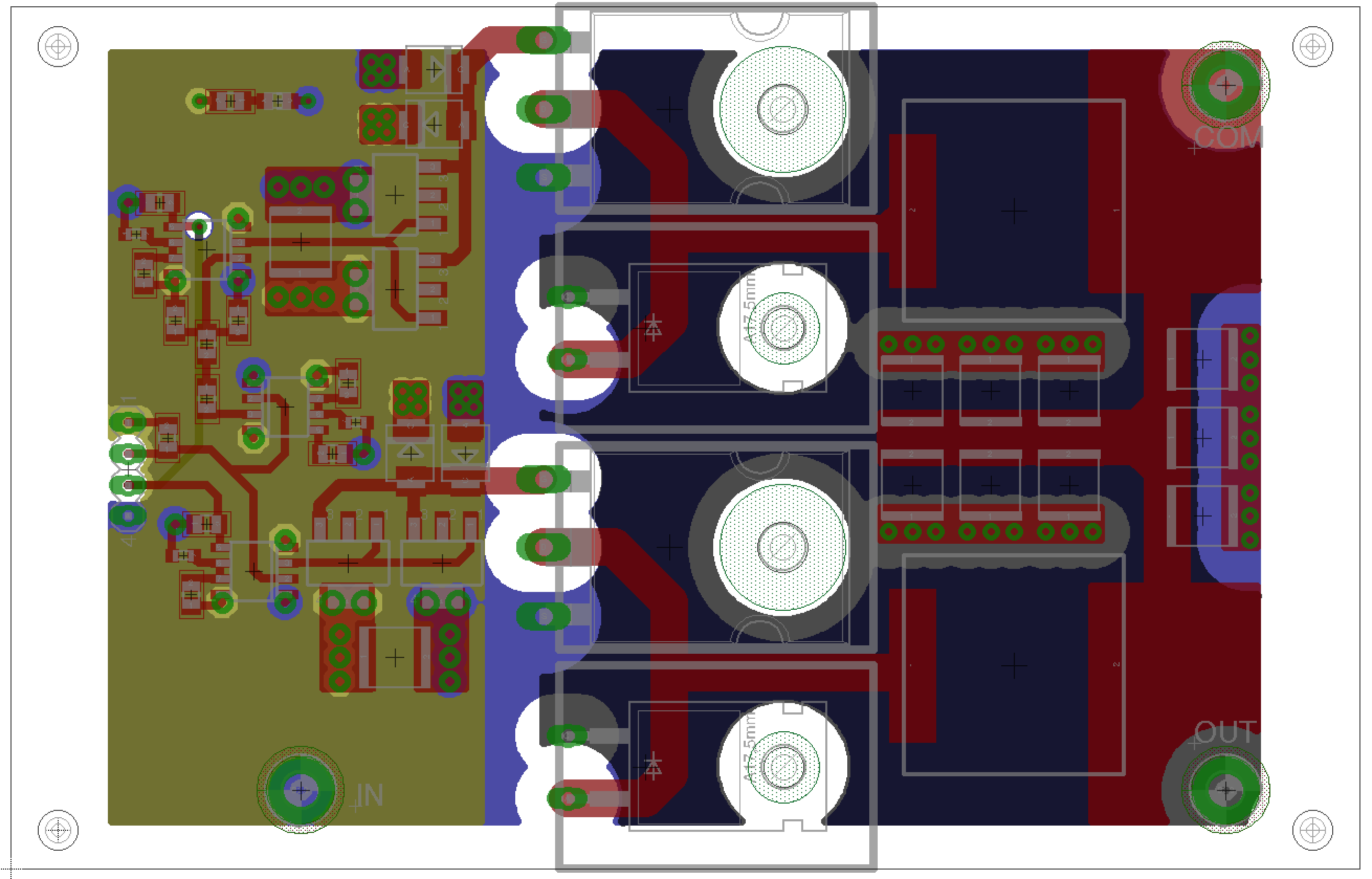
01/26/2016 at 01:50 • 0 commentsReplaced the unshielded inductors with shielded ones. Increased the switching frequency, which allows for smaller filter capacitance and a better power factor under light load. Power factor and efficiency at max load are unchanged. Layer order for high voltage planes was modified to reduce parasitic capacitance on the flyback traces and voltage stress on the board dielectric.
![]()
-
System Block Diagram
01/25/2016 at 04:08 • 0 comments![]()
Here's how all of the various boards work together. The multiple conversion stages are required to provide a high end-to-end efficiency as well as support throttle control and safety interlocks.
-
PFC Module
01/25/2016 at 03:12 • 0 commentsDesign of the PFC module for the AC-to-DC converter is nearly complete. Each module provides a 1kW output at 340V with a power factor of 0.99 and an output efficiency of 96% with an input voltage of 240 VAC. These modules can be combined in parallel to provide higher output power. Each of these boards contains two non-isolated buck-boost converters that can operate over an input range of 120 - 410 VDC or 90 -270 VAC with an external rectifier and EMI filter. The two converters are operate out-of-phase with each other to minimize EMI and the capacitor ripple currents. Each of these boards are controlled from a central board that provides the reference clock and feedback for limiting the output voltage when the output is not sufficiently loaded.
![]()
I plan to have the board and BOM finalized by the end of the week. I hope to build and test a single PFC module near the end of next month.
Ionic Thruster Power Supply
HVDC power supply that provides +54kV, -54kV, and -73kV with minimal voltage ripple and moderate output current.
