-
Enclosure
11/28/2014 at 01:40 • 0 comments** log in progress **
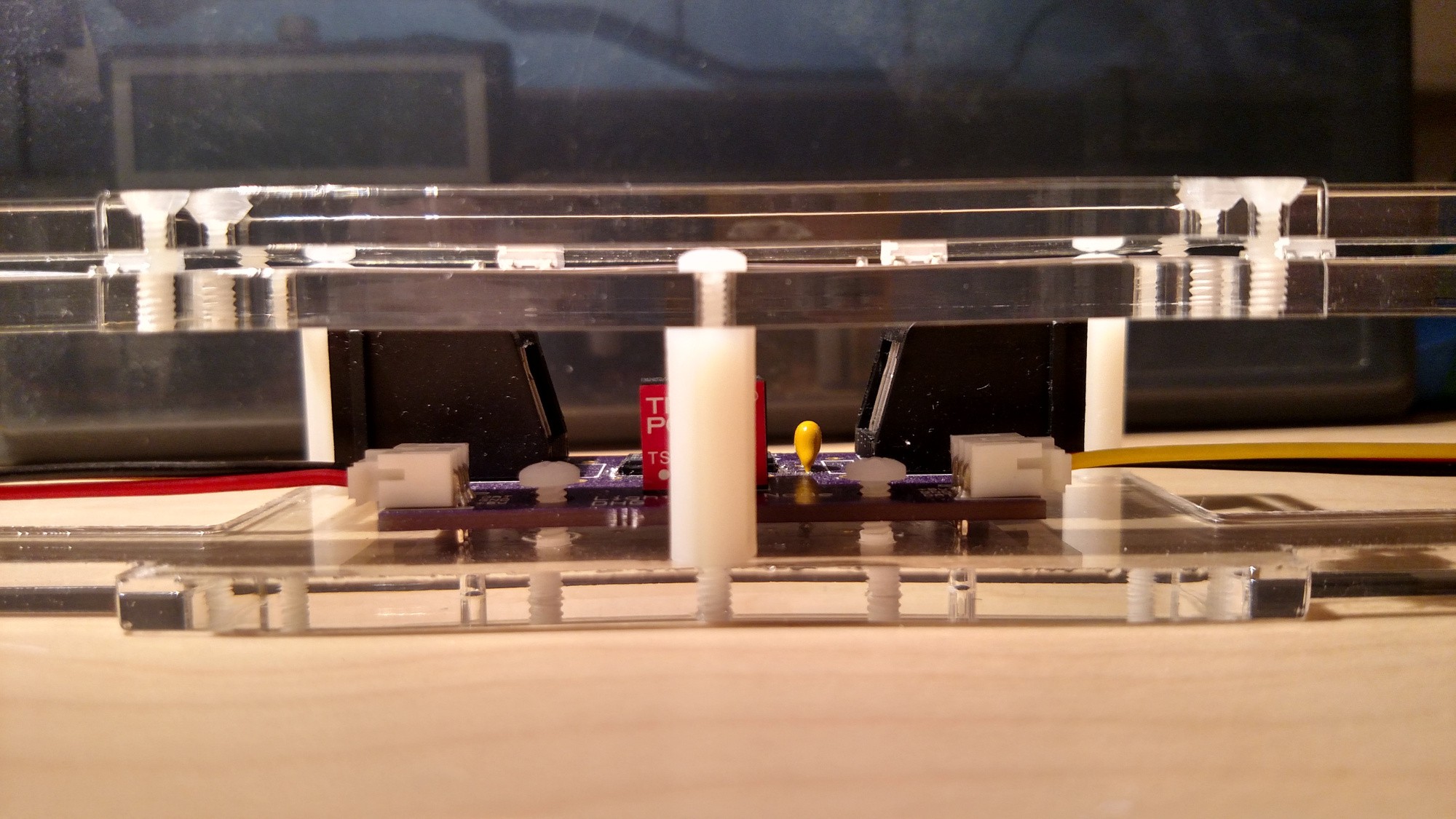
It took a lot of napkin sketches to come up with an enclosure that I liked for the wall-mounted LED strip + PCB assemblies as I didn't want to slap a rectangular box on the wall and call it good. I ended up designing a nifty 3-layer, laser cut acrylic assembly.
![]()
I'm pretty proud of this design for a few reasons:
- The transparent acrylic both allows me to show off my PCB design work and minimizes the visual footprint of the assembly during the day and other times when it is not in use.
- The top layers sandwich the LED strip to hold it in place which eliminates the need for any glue.
![]()
- The assembly looks reasonable mounted in either orientation (it's currently mounted 180 degrees off from the original vision seen above).
-
Hardware - Second PCB
04/28/2014 at 02:20 • 0 commentsI rearranged some components for the node pcb revision, added some mounting holes just in case, added the voltage regulator, and managed to unintentionally maintain the same footprint as the first iteration of the pcb.
(add pictures here)
I designed for a buck converter for it's efficiency and liked the TSR 1-2450 for it's small size and pin compatibility with TO-220 package LM regulators so I could use the cheaper regulators for testing. The buck converters are a little pricey at around US$9 from Newark.
-
Hardware - First PCB
04/28/2014 at 01:27 • 0 commentsHardware components on the PCB:
- RJ45 jacks for power and comms
- RS-422 transceivers in soic-8 package (my first foray into smd components)
- 3-pin JST for connecting to the LED strips
- Jumpers for selecting data direction
- Bypass caps and terminating resistor
EagleCAD has a pretty steep learning curve, but thanks to some Sparkfun tutorials and other miscellaneous Google searches the PCB design process went pretty well. I hand-routed each trace and it took a while before I had a layout I was happy with.
Thanks to OSH Park, two weeks after finishing the design I had three slick purple PCBs on my desk.
(insert image here)
A couple of changes noticed for the next revision:
- Move the jst connectors to the outside of the board to make it easier to insert/remove.
- Replace the two data direction jumpers with a single switch.
- Make the trace that links the +5V lines on the RJ45 jacks thicker.
- Use the two unconnected cat5 wires for power and ground.
Fortunately the board was pretty simple and there were no missing or mis-routed traces. My big mistake was with the power supply. I neglected to account for voltage drop over long cable runs, so sending 5V didn't cut it. The next revision should take 12V or so and regulate it down to 5V.
In working on soldering my first smd components I learned, counterintuitively, that a larger iron tip can make soldering small components easier. Who knew?
- RJ45 jacks for power and comms
-
LED Node Comms over RS-422
04/27/2014 at 23:06 • 0 commentsWhen I first tried to tackle the WS2812 signal's degradation over long distances the plan was to use an ATiny2313 on an RS-485 bus and send packets from the Teensy to the ATiny which would then control the LEDs. I chose the 2313 so I'd have to work with limited resources just to add some fun. I had things working well with a lightweight message protocol and the rs-485 running quite fast. Then I had the realization that maybe I could just run the ws2812 direct off of rs-485 transceivers. Like magic, it worked great. A lot of work went into the ATiny stuff that will remain unused, but it was good to learn anyway.
Since I'll be running point-point direct from the Teensy to an LED strip and then from one strip to the next, the protocol is RS-422 instead of the multi-point RS-485. Transceivers typically do both, the main difference I noticed was that the differential lines are terminated with a resistor only at the receive end.
A month or so after working through the new, simple solution, this link showed up on HaD: http://www.teknynja.com/2014/02/driving-ws2812neopixels-rgb-leds-over.html
-
Teensy FFT Notes
04/27/2014 at 22:34 • 0 comments(fft notes here)
-
First Post
04/27/2014 at 22:29 • 0 commentsAfter creating a typical MSGEQ7+Arduino+WS2812 music visualization display and successfully taping the pieces, including breadboard, to the wall for a party, I decided I'd go all in on a more refined solution.
The original goals were to:
a) Run a FFT instead of using the MSGEQ7 so I could have finer control over frequencies.
b) Design and fab a PCB.
c) Desgin an intersting and non-tacky enclosure.
d) Tackle the ws2812 over distance problem.
e) Make it controllable over bluetooth.
 dhgoldberg
