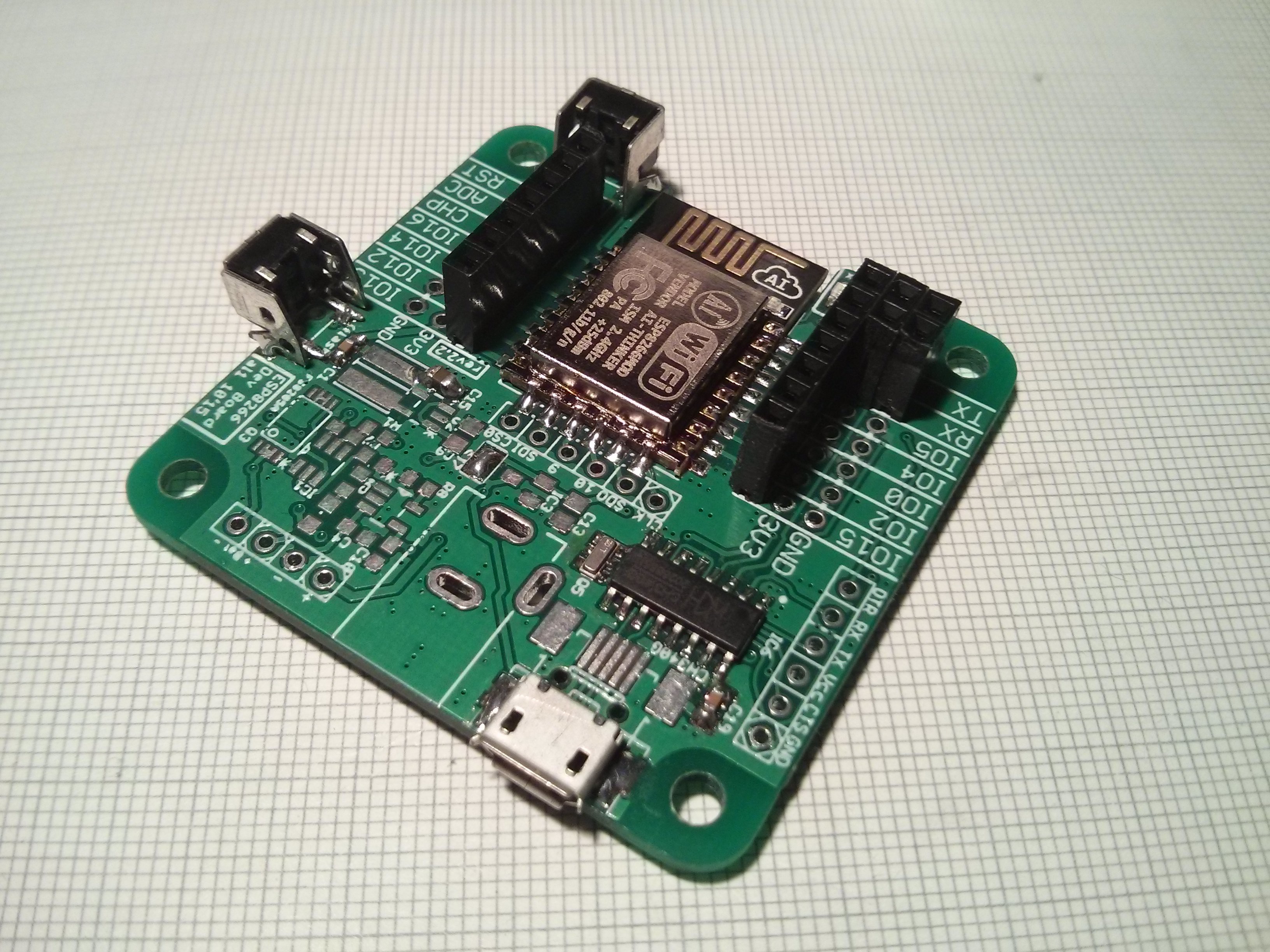
#ESP8266 (ESP-07/12) Dev Board by @al1
In the Ignore this ESP8266 board build I mentioned preferring a completely integrated platform to develop on so I'm really happy to have one of [al1]'s boards.

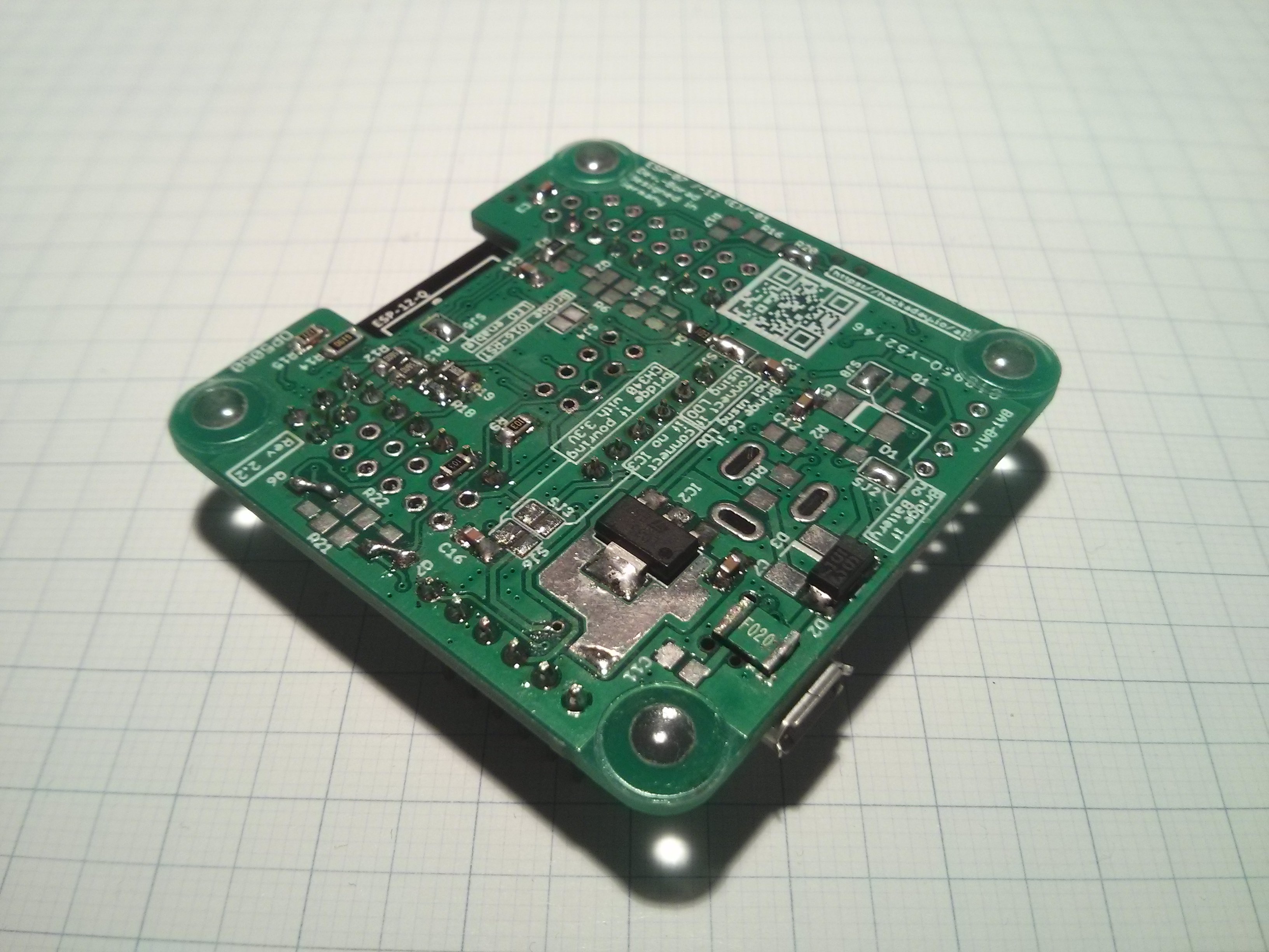
It's amazing how many features he managed to stuff into this board... though I'm only using the bare essentials. All the optional features make assembly a bit more difficult but that's to be expected and I really like the various options for powering the ESP and the CH340G available on this board.
Because I didn't have a SOT23-3 regulator I first tried powering the ESP and CH340G from the same (main) 3.3V rail which didn't work with any amount of capacitance. As soon as the ESP got going it dropped the voltage below 3.3V which is the (absolute) minimum operating voltage of the CH340G. Therefore I changed it's supply to the 5V from USB and added the voltage divider on the TX line that I initially wanted to avoid.
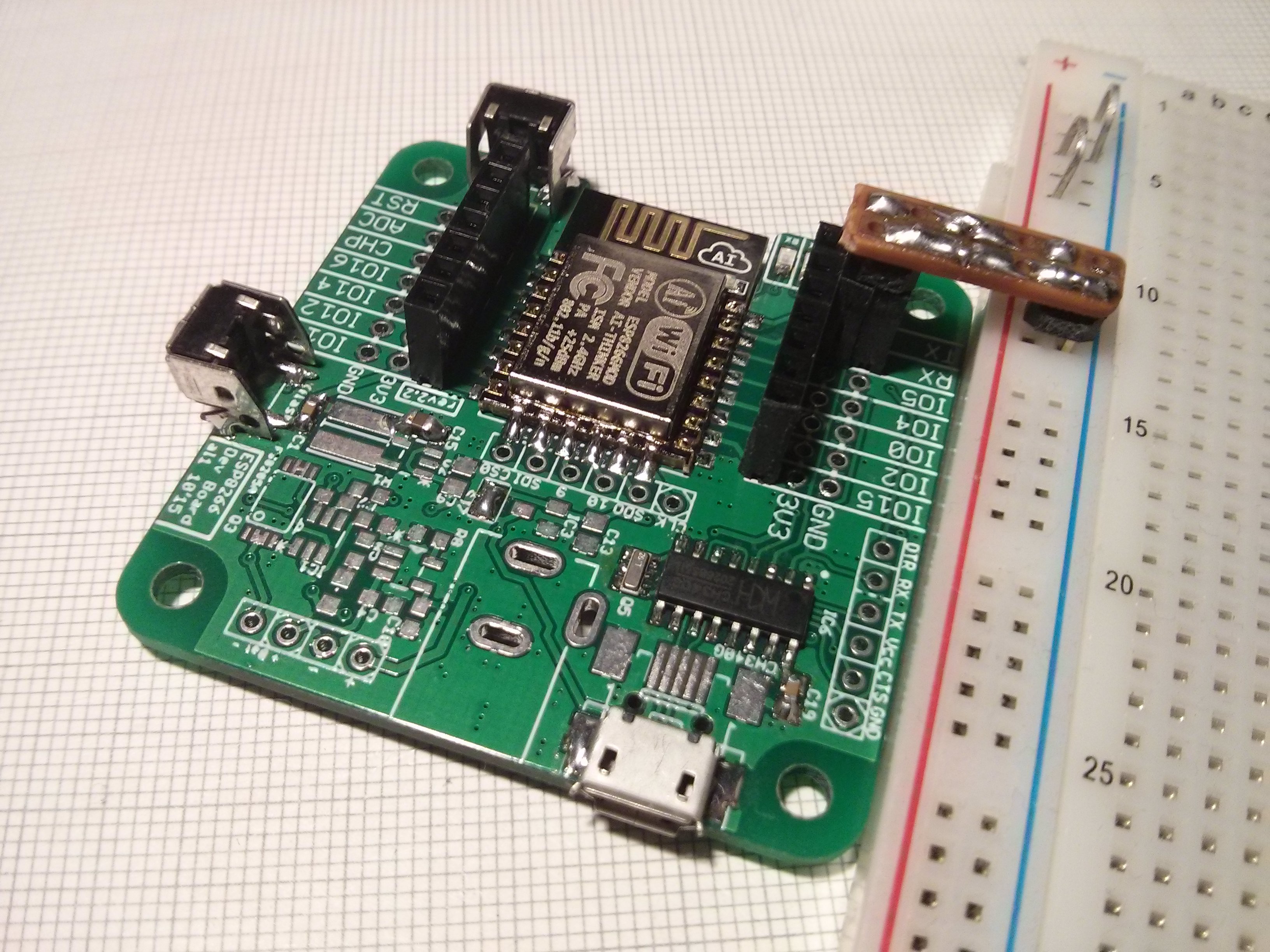
As you can see above I also didn't have the appropriate tact switches but I made the ones I had work. Also gave it the rubber feet and breadboard power rail treatment:


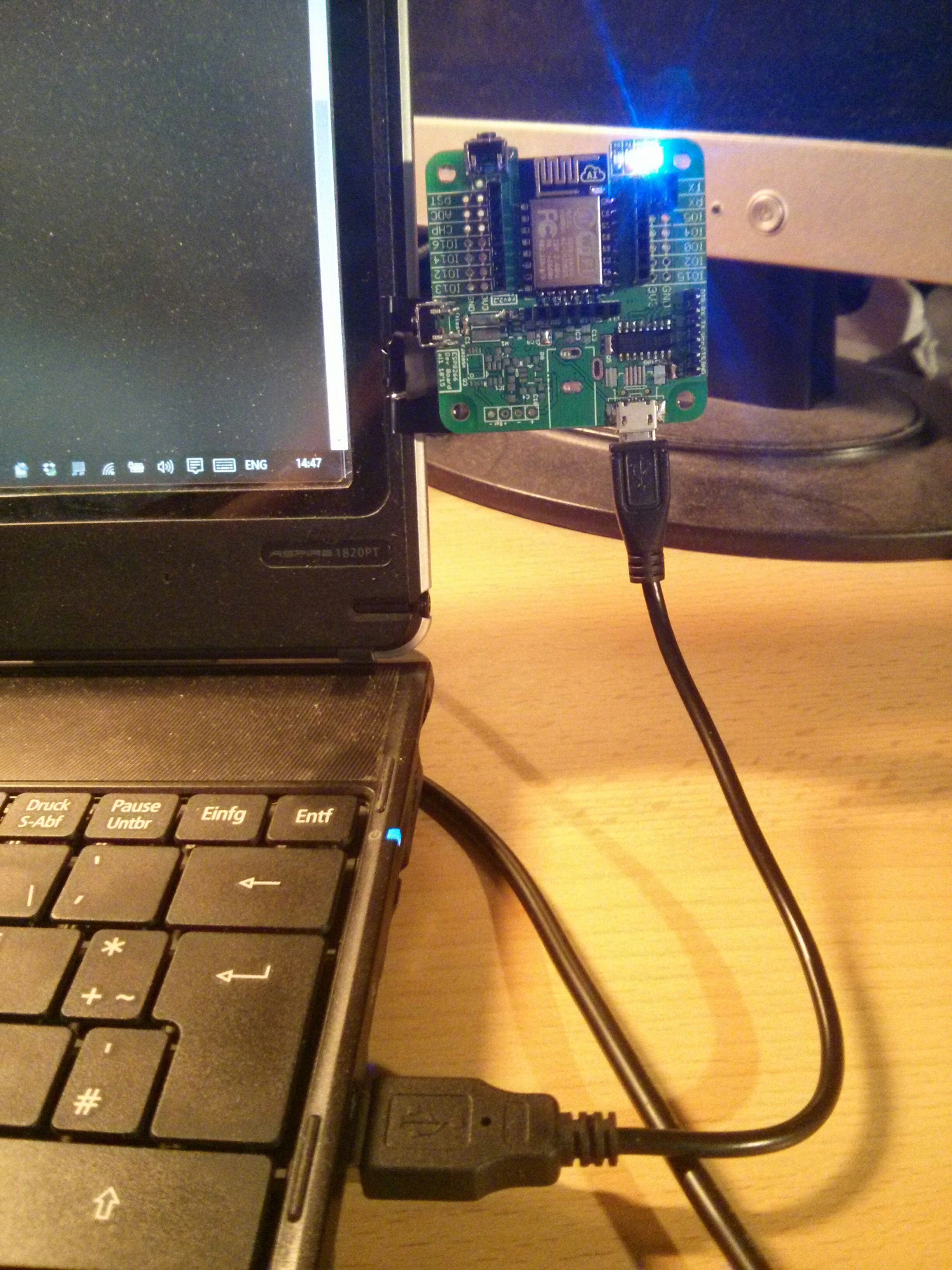
Getting back to my point of preferring an integrated devboard (which ties into me actually having my laptop on my lap a lot of the time), it makes it really easy to do this:

Granted, the CP2102 modules I use aren't that much bigger than the USB-A plug but it's noticeable and knocking the plug against a chairs arm rests isn't as big of a deal as possibly breaking the module.
 Stefan Lochbrunner
Discussions
Become a Hackaday.io Member
Create an account to leave a comment. Already have an account? Log In.
Nice! This is actually the second soldered rev2.2 board.
The problem with powering the CH340 from the main 3.3V regulator was known (in rev1), I thought I fixed that with this revision. But I never rechecked that myself. Thanks for the bug report.
Are you sure? yes | no
Thanks, I did take quite some time though ;)
At first I thought shortening the path from the regulator to the CH340 would help so I bridged the output from the regulator (the large pad) to the via going to the CH340's supply near the serial header but the problem persisted. I think I went as high as 100uF but from some quick calculations I think it would take way more. However, if one uses the CH340 there's 5V available anyway and if one uses it battery power you don't need the CH340 so it's really not a big deal.
Are you sure? yes | no
Mh.. maybe I will just cut out this CH340 powering option in the next revision. So no one will be trapped again.
Are you sure? yes | no
I think it would suffice to amend the 'Power supply' section in the project description. Just saying that there are two options to power the CH340 and if you want to power it with 3.3V you need the additional regulator would be enough.
Are you sure? yes | no