Stefan Lochbrunner
-
ESP8266 (ESP-07/12) Dev Board by al1
01/20/2016 at 14:06 • 4 comments#ESP8266 (ESP-07/12) Dev Board by @al1
In the Ignore this ESP8266 board build I mentioned preferring a completely integrated platform to develop on so I'm really happy to have one of [al1]'s boards.
![]()
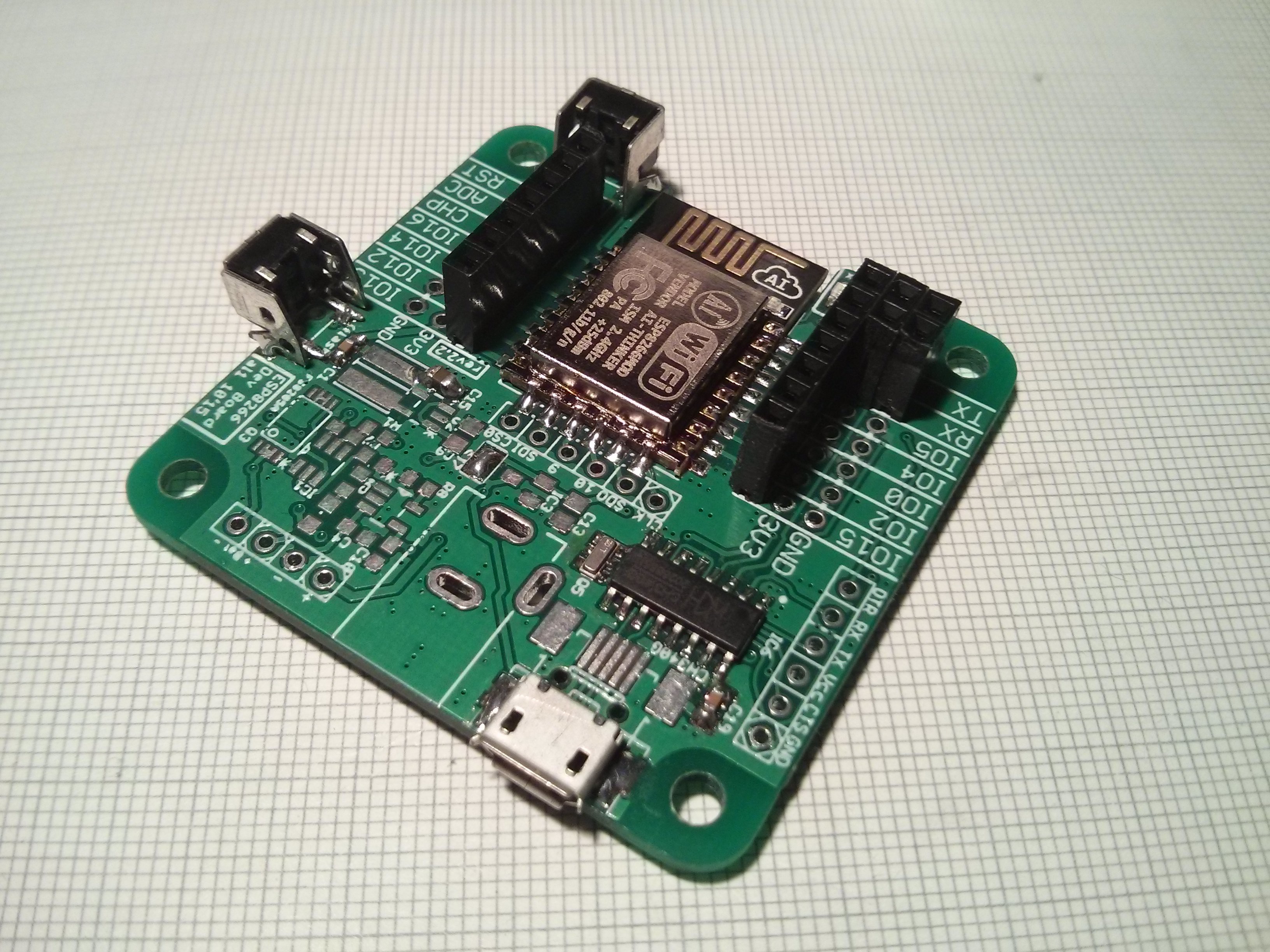
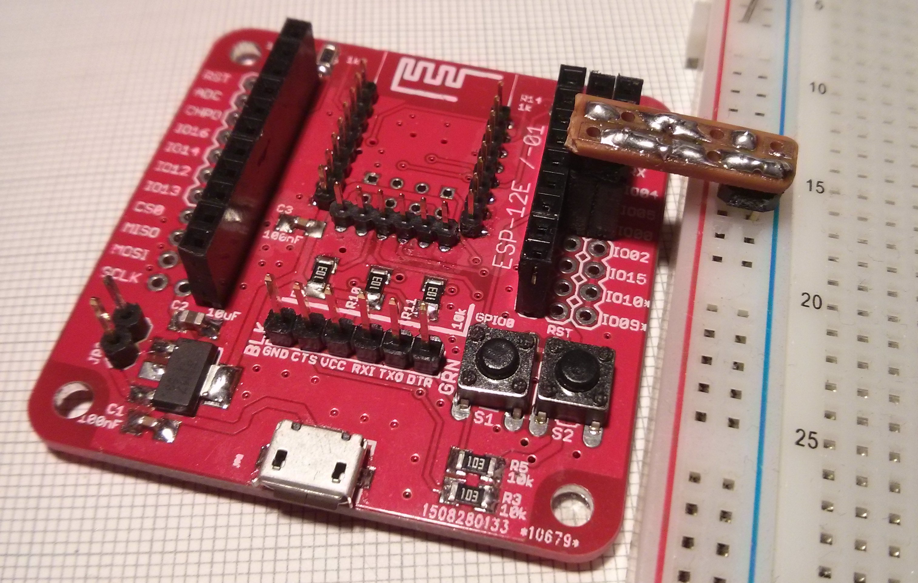
It's amazing how many features he managed to stuff into this board... though I'm only using the bare essentials. All the optional features make assembly a bit more difficult but that's to be expected and I really like the various options for powering the ESP and the CH340G available on this board.
Because I didn't have a SOT23-3 regulator I first tried powering the ESP and CH340G from the same (main) 3.3V rail which didn't work with any amount of capacitance. As soon as the ESP got going it dropped the voltage below 3.3V which is the (absolute) minimum operating voltage of the CH340G. Therefore I changed it's supply to the 5V from USB and added the voltage divider on the TX line that I initially wanted to avoid.
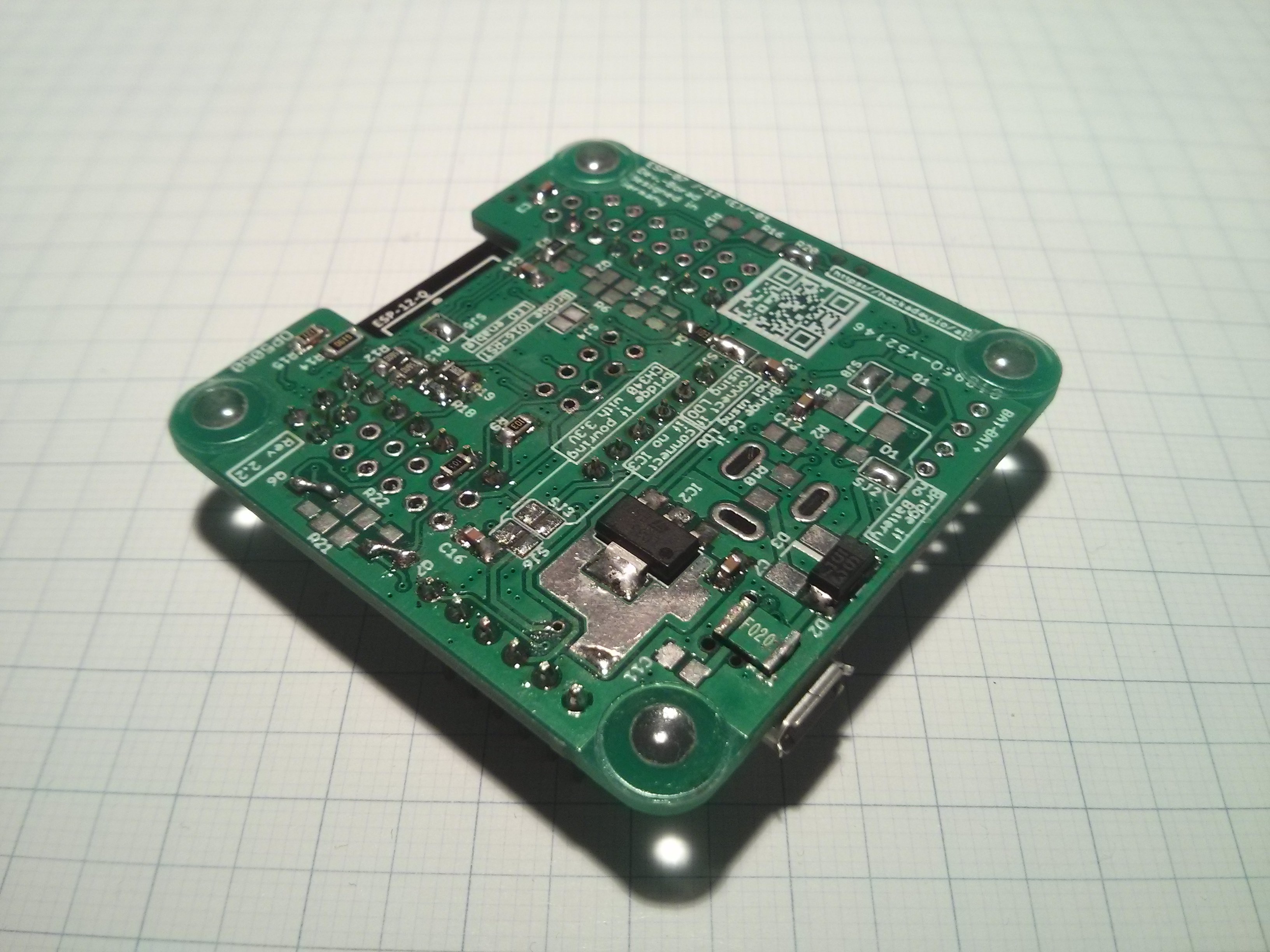
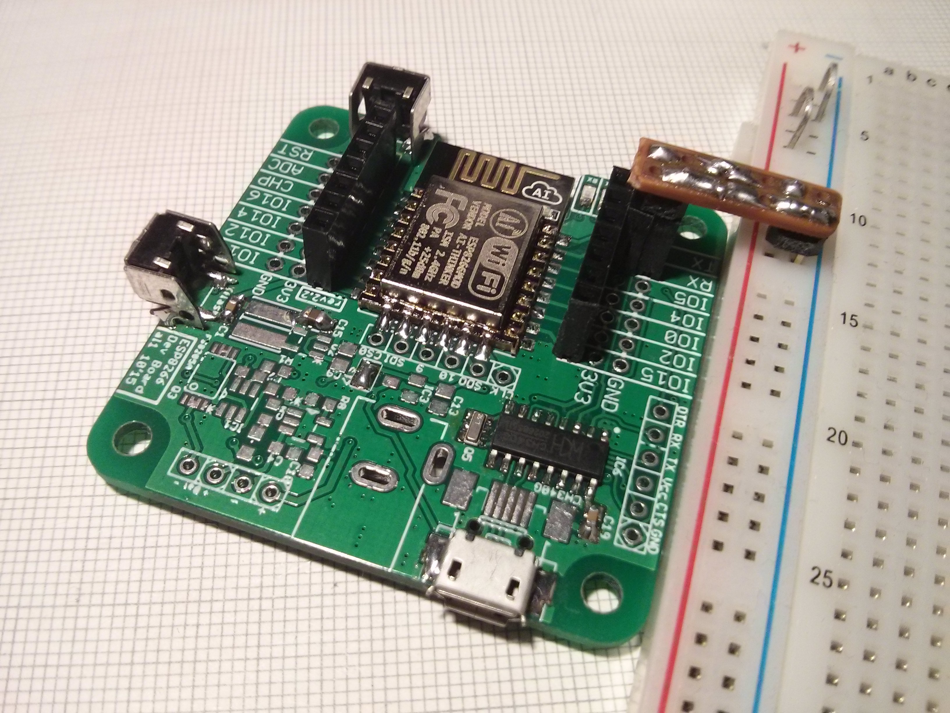
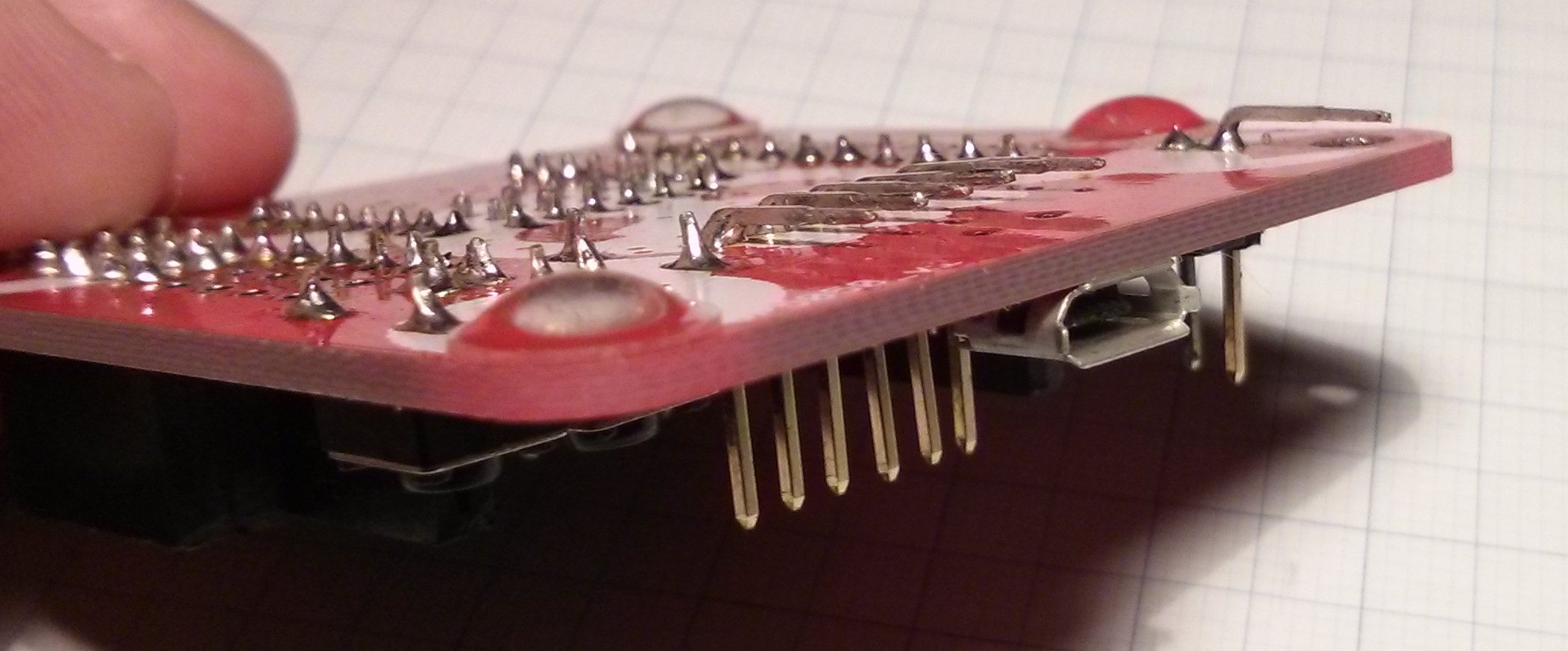
As you can see above I also didn't have the appropriate tact switches but I made the ones I had work. Also gave it the rubber feet and breadboard power rail treatment:
The diode I used on the back is a bit large for the rubber feet but at least all of the bare contacts are off the surface.![]()
![]()
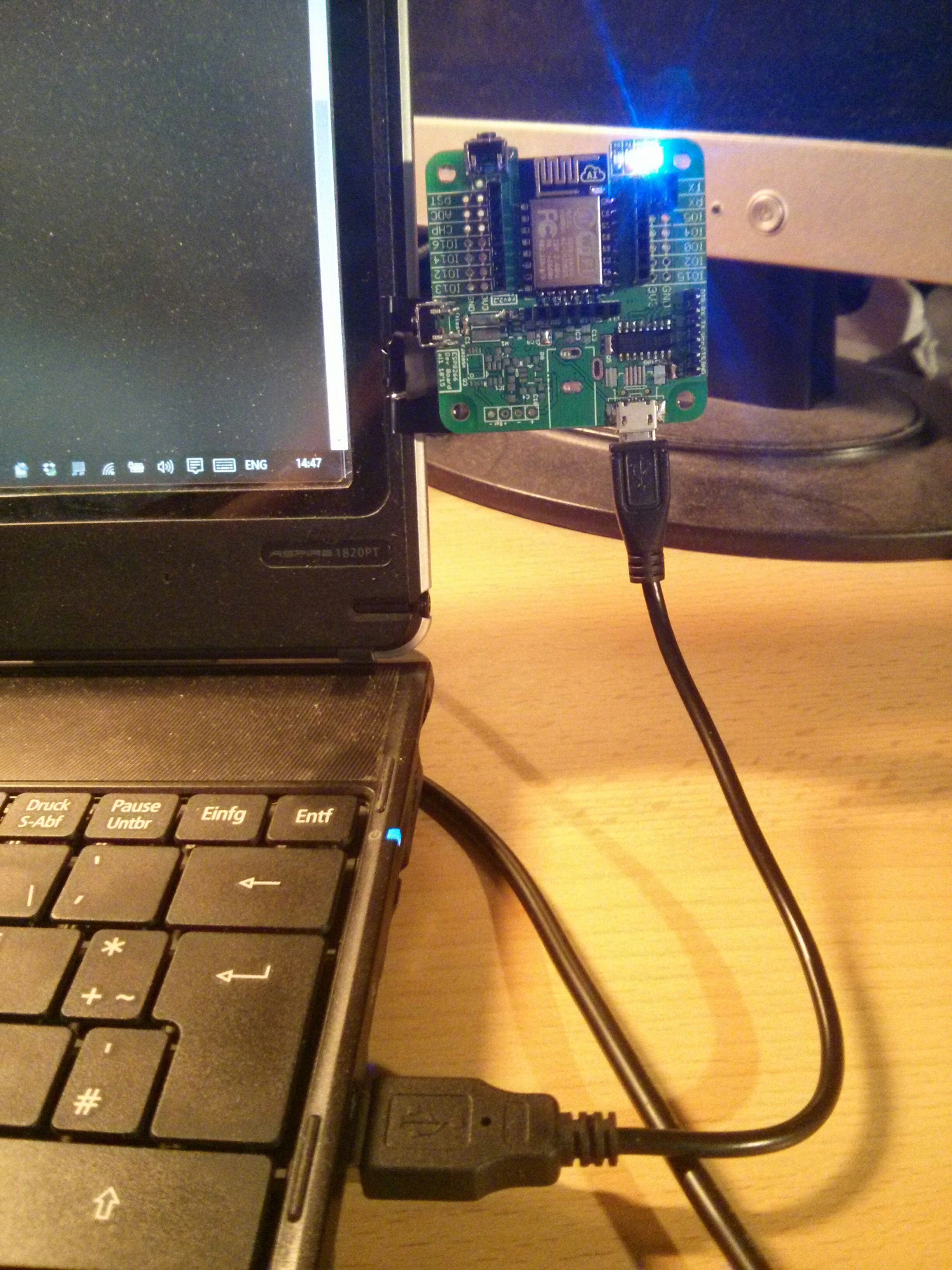
Getting back to my point of preferring an integrated devboard (which ties into me actually having my laptop on my lap a lot of the time), it makes it really easy to do this:
![]()
Granted, the CP2102 modules I use aren't that much bigger than the USB-A plug but it's noticeable and knocking the plug against a chairs arm rests isn't as big of a deal as possibly breaking the module.
-
PIC16F1xxx Arduino based programmer by jaromir.sukuba
01/20/2016 at 01:36 • 0 comments#PIC16F1xxx Arduino based programmer by @jaromir.sukuba
I wanted to look into programming PICs for a while and I felt like the PICkit 3 would be the way to go but it's somewhat expensive and I couldn't quite get myself to buy one of those clones so when I first saw [jaromir]'s project I knew I had to give it a try. Sort of my version of #Operation: Learn the PIC.
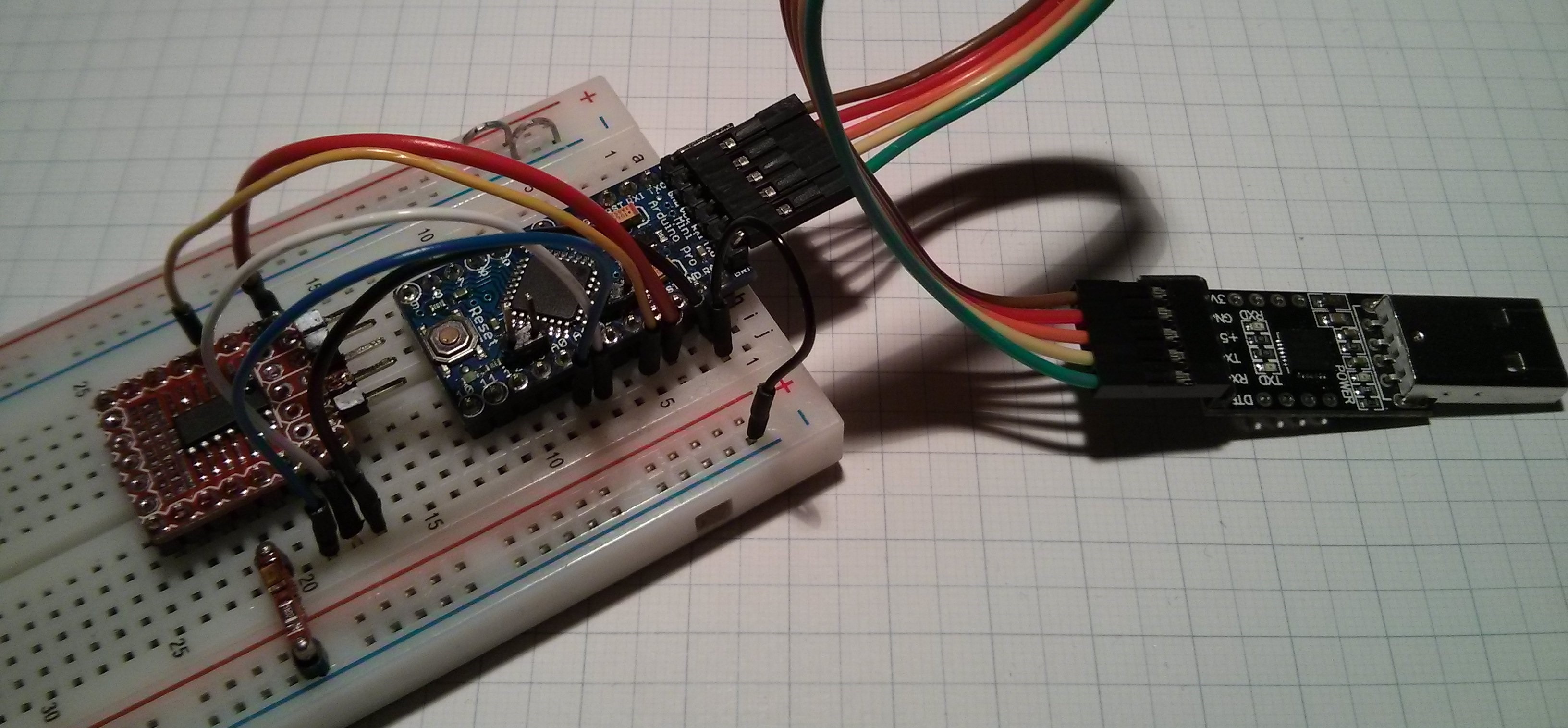
As [jaromir] describes, the programmer has its limitations but for someone just wanting to get to grips with the basic process it sounded pretty good and so it was. All you need to get started is any Arduino with an ATmega328 so I pulled out a Pro Mini and CP2102 and hooked up the basic circuit:
![]()
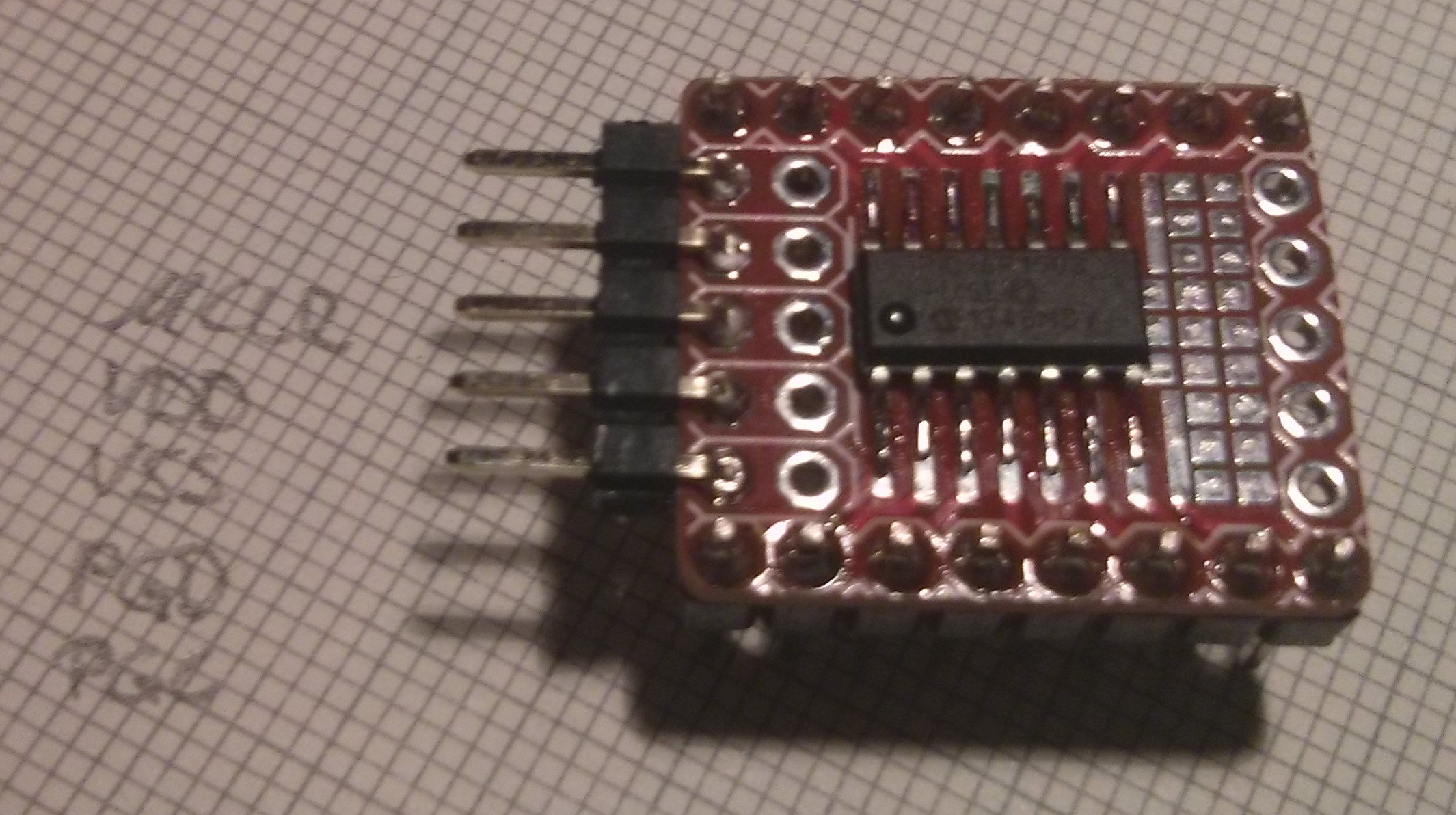
I had previously PICked up [get it? ...sorry ;) ] two compatible PICs from the 16F1xxx series that were not yet tested with [jaromir]'s programmer such that I could contribute a bit of information to the project. Namely I got a 16F1454 in a DIL package and a 16F1503 in a SOIC package. To use the latter one I soldered it to one of my breakout boards and added the typical ICSP header:
![]()
![]()
I later also added a pull-up on !MCLR and a decoupling capacitor and might also add some LEDs to this board.
To get started on the software side I simply followed [jaromir]'s how to which has all the necessary information to set up the programmer and I couldn't have wished for better instructions.
Even both chips were not supported at the time I wanted to see what the programmers response would be so I ran
pp2.exe -c COM3 -p -n -t 16f1454 file.bin
to check the device signature to which I received an error message stating that this CPU type wasn't supported which makes complete sense. So I went back to the how to which also includes instructions on how to modify and build the software side of the programmer. From looking at the source file it was pretty obvious where the necessary device compatibility had to be added and which information was required so I took to the datasheets to find the required information. Flash size, device ID and device ID mask were easy to find with the search function but I couldn't figure out what the right page size should be. After searching up and down through the 'Memory Organization' chapter, where I figured this information had to be, I asked [jaromir] for help to which he posted yet another set of very detailed and helpful instructions. Those pointed me to the right chapter in the datasheet and I continued adding my PICs to the source file and compiling a new executable.I cannot stress enough how great [jaromir]'s instructions are. I admit that this problem was mainly due to my own laziness but if I had one suggestion it would be more detailed comments in the source files. It's kind of a moot point now with these detailed instructions but I think it's good practice.
Anyway, now that the programmer supports the two new PICs the above command stopped complaining about the CPU but instead about the input file (which was non-existent) and so began my struggle to understand MPLABX. This probably took longer than setting up the programmer so it seems strange that I'm keeping this part quite short but I was surprised that I just couldn't find a good beginners tutorial... by which I mean a tutorial for very lazy people like me. If you can recommend a good tutorial I'd be very grateful. Suffice it to say that I eventually got both PICs to blink and at the end of the day that's what counts, right? Right. (probably not. whatever. it's late). Have some gifs:
[I assure you the frames are taken from a video ;) ]![]()
![]()
If someone just wants to test their PIC16F1454 or -1503 or just the programmer without having to go through the whole MPLABX situation, I have uploaded my .c, .hex and .bin files to this project.
When flashing a chip I like to use the -v parameter with a value of 2
pp2 -c COM3 -v 2 -t 16f1454 file.bin
which prints some dots (1 per flash page) that give a nice sense of progressOpening serial port Device ID 0x2CE2 Programming FLASH (4096 B in 128 pages)................................................................................................................................ Programming config Verifying FLASH (4096 B in 128 pages)................................................................................................................................ Verifying config config 1 OK: 39E4 config 2 OK: 3FFF Releasing MCLR
I might try to implement a progress bar as a little exercise for myself but this is probably a bit down the line. Another thing I think would be cool/useful is to port the firmware to other AVRs, namely the ATmega32U4 such that one could use the Pro Micro as a one stop solution or maybe to the ATtinyx4 (together with a CH340G) just because a '328 seems a bit overkill.As I mentioned above, my version of [jaromir]'s programmer is just hooked up on a breadboard right now so I'll probably make an adapter for the Pro Mini to get the 5-pin ICSP header.
Update 2016-01-25:
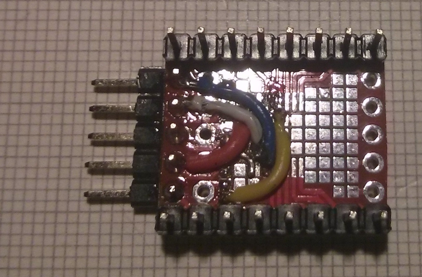
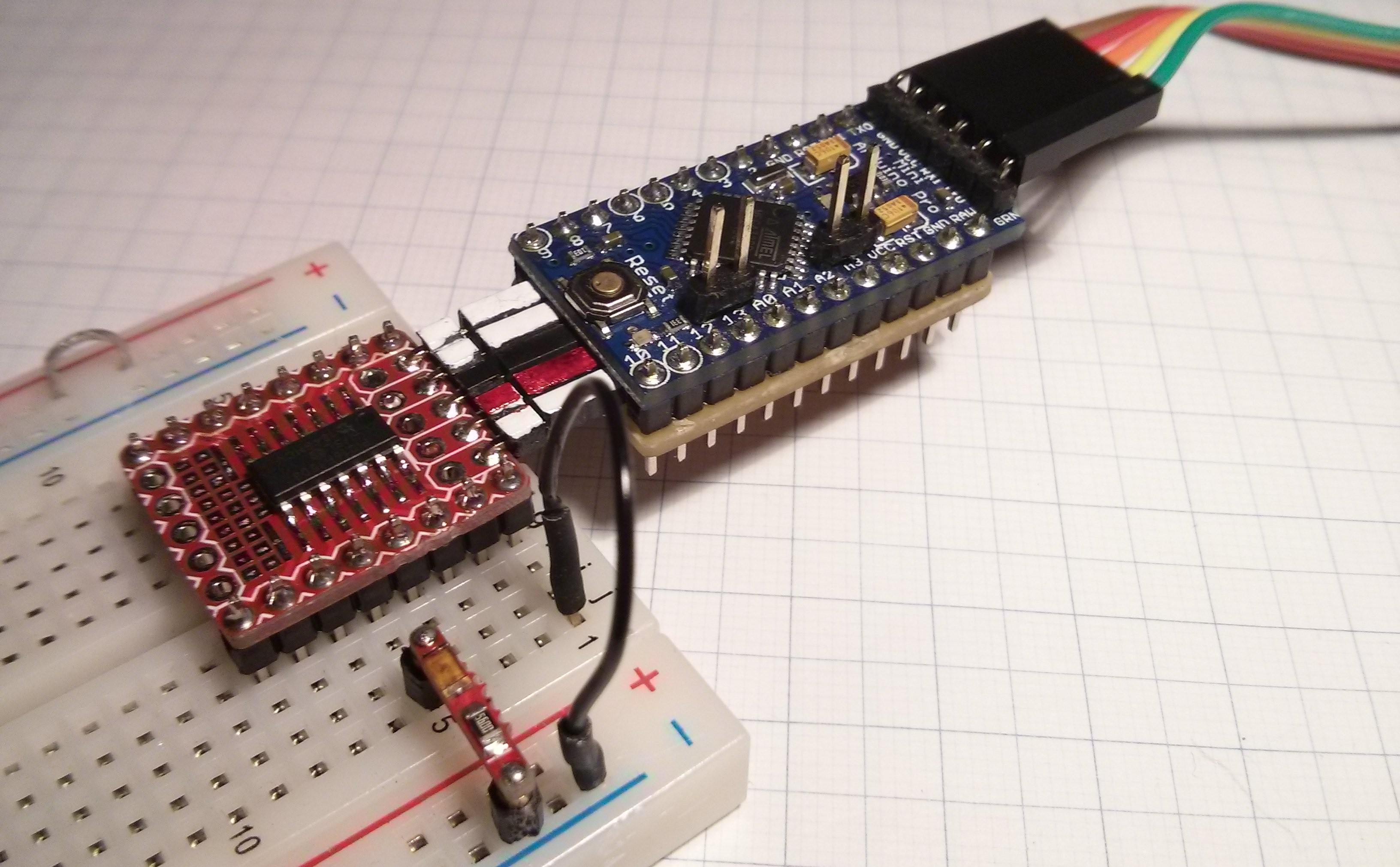
I got around to making that adapter for the Pro Mini:
![]()
At first I thought I'd just use female headers to connect to the Pro Mini but I really liked the slim form factor of stacking the two boards. However, I wanted to maintain the flexibility of using female headers so I used some of the inserts/clamps from those headers directly soldered to the stripboard:
![]()
I used two on the GND and Vcc connections and a few extra ones on other (not used) pins for stability; the MCLR, PGD and PGC connections are on the other side. Of course I tested it and it works quite well.
-
Ignore this ESP8266 board by davedarko
01/19/2016 at 23:45 • 2 comments#Ignore this ESP8266 board by @davedarko
![]()
![]()
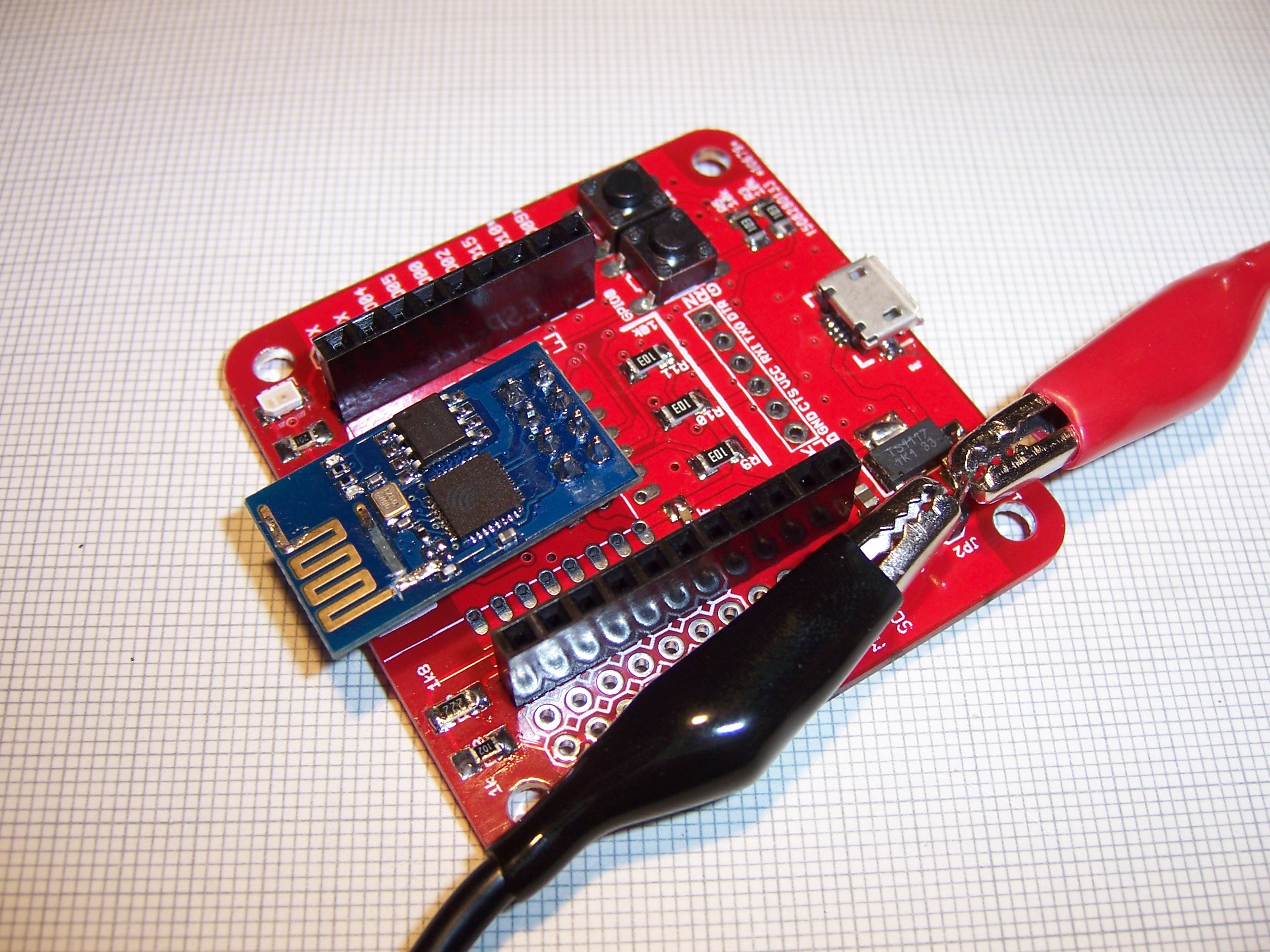
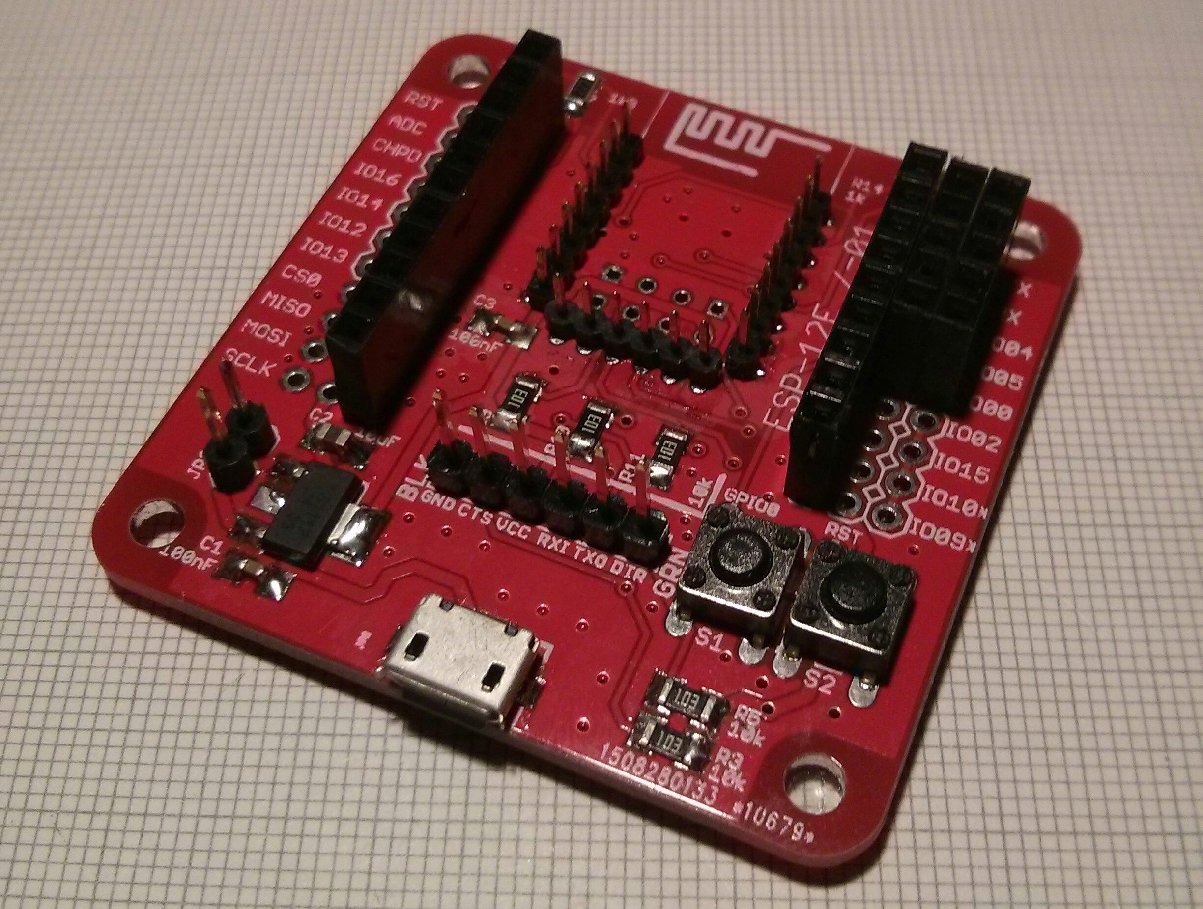
It has been a while since I got the boards and at the time I left some thoughts on the project page. I really like its simplicity which made assembly very easy. To develop on such a board I'd prefer an onboard serial converter just to eliminate having to chain several gadgets together but I have some use cases for the boards nonetheless:
I've added 2mm headers to the ESP-12E footprint such that I can just plug in an ESP-12E or an ESP-01. I use this board to test new ESP modules to make sure they work after their month-long trip.![]()
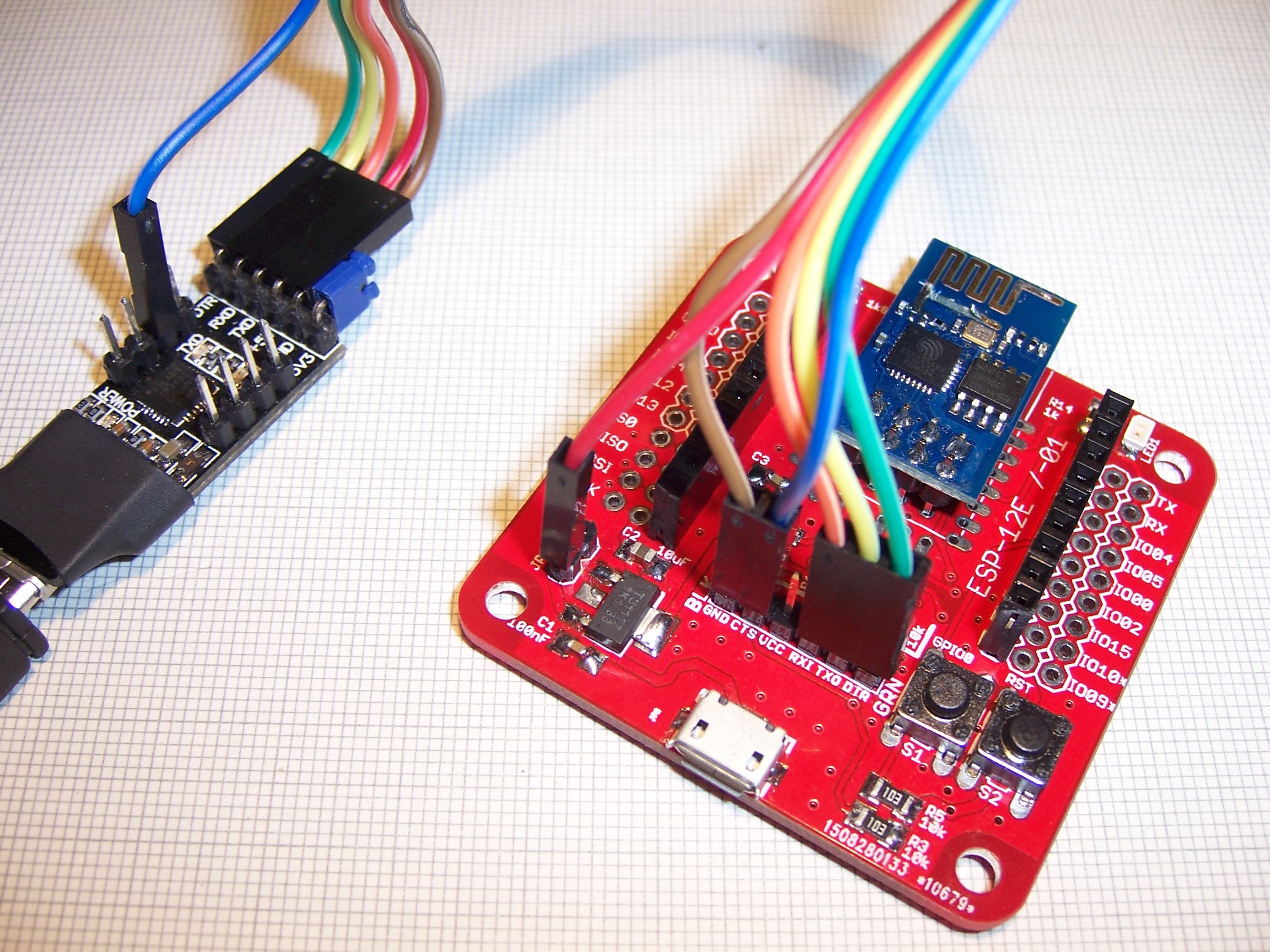
I haven't implemented the second use case yet but I plan on making the other one into a wireless serial bridge using the ESP-Link firmware and a virtual serial port tunnel to make it compatible with just about every program/tool out there. The reason for this is that I do most work on my laptop when it's actually on my lap and this way I won't have to worry about the USB cable pulling the devboard and breadboard off my desk.
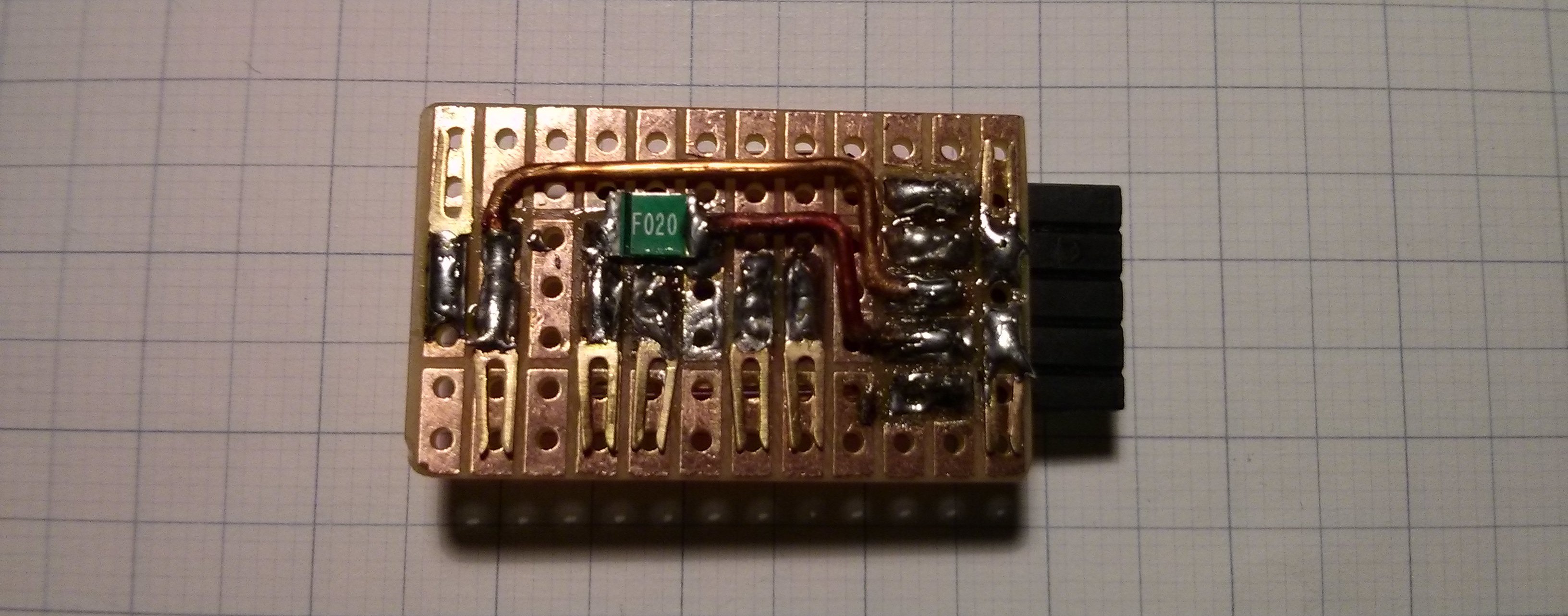
And finally here are some mods that I made for/to the board:
Simple adapter board to connect power rails. This was more feasible than using those female headers with long pins and plugging it into the top.![]()
I used angled headers for the serial header and the Vusb/Vin pin. The idea was to make it possible to plug it directly into the serial converter (or some in-between adapter board) and have them not be perpendicular to each other. Also added some rubber feet for good measure.![]()
Another installment in the series 'Me building...'
It was between this or 'Me building other people's projects... with a vengeance'