anthony.webb
-
Cleaning up the 3D design files
01/25/2016 at 06:10 • 0 commentsCleaning up some of the 3D designs and bringing them up to speed with the machine we actually built. We opted to go with a far more heavy duty frame than we originally planned, cost increase was minimal. As compared to our previous plan for the bed, this new bed can be adjusted up and down very easily, which came in handy as we fine tuned for the position and travel of our head unit. Attached are shots of both with and without the bed. On the unit we built we bolted aluminum guides onto the bed in order to easily put parts and board into the same place again and again. You'll see those details in the upcoming videos.
Another note (spoiler) we were able to actually do our first pick and place operations! More to follow.
![]()
![]()
-
Z Height
01/25/2016 at 06:08 • 0 commentsI've heard comments mentioning that I may not have sufficient Z height. I've never built a machine like this much less been around them so the likelihood of me painting myself into a corner is pretty high. Funny thing is I have been worried about the Z height, only I have been concerned that I have too much room, not too little. The good news is the bed can easily slide up or down the legs and be attached right in the sweet spot.
Here is how it measures out today...
There is 31mm (~1.25in) of space between the lowest tip and the top of the steel. The max travel of the fully extended tip is 21mm, which leaves me 10mm (just under 1/2in) that my board mounts will need to lift up the board (at a minimum) so the tip can reach the board. Same goes for parts. Since I will probably be designing/milling my own mounting system I can really make them however thick they need to be, but I didnt really want them to be much over 1/2 inch. Does this sound reasonable?
-
Hiwin rails look a lot better
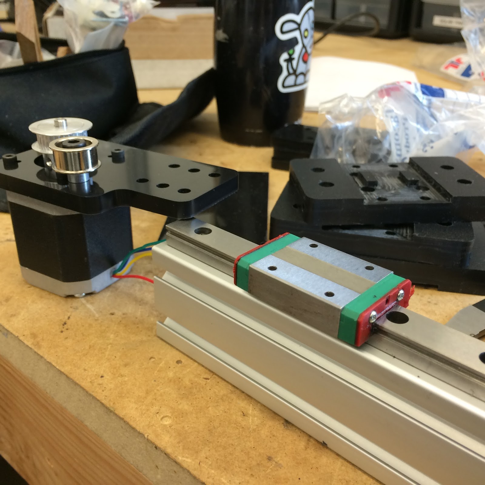
01/25/2016 at 06:06 • 0 commentsSpent some time with the rails from HIWIN over the last couple days. And I can tell you straight up, these things are in a totally different class than the cheap chinese rails found all over the web. Are they on par with the pricey THK's? Time will tell, but I can tell you these things are butter smooth.
I've yet to have any binding on a passive rail that is over 20 inches (500mm) away despite only running a single slide on the passive slide, I bought 2 slides for the passive side thinking perhaps I might need to explore have a wider base on that side for stability, not needed. I've done some pretty high speed jogging and analysis and the drift over the course of them has been less than 50 microns (near perfect). In short, these things are great, definitely keepers.
These are the first rails I have tried that I would feel complete confidence putting into production today. The only knock? They don't have a grease nipple like the THK's, I'm not sure if it is an option on these small 12mm rails either. But for the amount of use that a typical maker PNP system might see it might not be needed.
![]()
![]()
![]()
![]()
![]()
![]()
![]()
-
Bed installed
01/25/2016 at 06:03 • 0 commentsGot the final bed installed. size is about 22 inches square. It is 3/4 inch mdf with a layer of 12 gauge (~1/8 in) galvanized steel laminated to it. It is probably a bit overkill but gives us a nice heavy base to stick magnetic holders and boards to.
![]()
-
Cheap chinese rails test results
01/25/2016 at 05:59 • 0 commentsA little note on some of the test results, and a movie of the process.
As I mentioned earlier, I built a tinyg driver for firenodejs and am using that to test the precision of my design using various rail options. I first mounted the cheap chinese rails I sourced from here: http://www.robotdigg.com/product/493/MGN12-1H-L600+Linear+Rail+and+Carriage+for+Kossel+XL
I have had these rails on for quite a while. I can start by saying that these things are cheap in every single way, and I dont mean "kind of cheap". The literally clank their way down the track, even after cleaning and lubing them up real good. Of the 3 I got 1 was VERY bad. I put that one on the X becuase I figured as long as it was directly driven by a motor it might be OK. I took the best of the 3 and put it on the passive rail. Hoping to make some lemonade.
Based on my tests the machine would move maybe 8-9 times nearly perfect. Below is a video of the cheap rails in motion, as you can see, pixel perfect precision (each pixel is about 50 microns) As you will see, motion is perfect during this leg of the test. BUT, inevitably, and eventually, that catching, binding comes back to bite you, and when you bind in a movement, it might throw you off as much as 1mm. The binding only occurs in the Y axis, that is the one with that passive rail that I thought might bind on me, it does. The good news is that is the rail with the worst rail/slide combo I had, and believe me, it is TERRIBLE. Yet in all the test it NEVER was off more than 50 microns, pretty impressive.
This leads me to my conclusion on the cheap chinese rails... they will work, IF you actively drive them. If you actively drive them they will be accurate too. Be aware that you will need to crank up the pots on your stepper drivers to deal with the friction, but they can work. That said, after I began the rail swap to the second set I will test, I found the rails/slides to be very dirty, a few metal shavings here and there. I'm not convinced that these will last, so even if I could make them work, I'm probably not inclined to every build anything with them again. $70 bucks down the drain all in the name of science :)
Moving along to the Hiwins... for now here is a video of the testing procedure:
-
Downlooking Camera
01/25/2016 at 05:55 • 0 commentsI realized that I didnt get a great shot of the down looking camera yet. It kind of hides out behind the Z head. At any rate the Z head attaches to a couple delrin caps that cover a small chunk of extrusion which mounts to the slide. There is a set screw (which is probably not needed, the delrin is a very tight fit) The camera appears to be supperb and has a nice focus ring up top. Only downside was that when focusing, the wire would want to turn inside the housing, which in turn rotated the camera too. So I took off the cap and put a small dab of silicon in there, problem solved. Time will tell if this camera is a great solution or not, but for now openpnp seems to like it and I am happy with how rigid it is, the minimal offset from the pick tips, easy focus that is very accessible, and how well it nestles in there without needing separate mounting bracket. Camera we are using is this one http://www.ebay.com/itm/121292898829
![]()
![]()
![]()
-
Building a bed
01/25/2016 at 05:54 • 0 commentsAlthough testing while attached to the benchtop worked initially, we knew eventually we'd need a real bed. Today we made some more progressing in finalizing one. I am very happy with the rigidity of the machine, it is pretty bombproof in this config. Getting some 3/4MDF for the bed which will then have 1/8" galvanized steel on top for a firm surface to magnetically attach board holders, strip feeders, trays, etc in whatever config I need. Left plenty of extrusion exposed all the way around to attach feeders we well.
![]()
![]()
![]()
![]()
-
Overheating motors
01/25/2016 at 05:50 • 0 commentsSome new developments. The motors I had wired up to the tinyg were 0.9 400 step per revolution steppers. They were moving pretty well, but I wanted to ensure that they were always powered during my tests. Somewhere along the way in tinkering with them they overheated and melted almost entirely through the 1/4" delrin mount. So, I had to build new mounts, haha.
At any rate, the 400 step steppers I had just didnt have enough torque to hit the target rapids I was looking to achieve (250mm per second) So, after building new mounts I installed 1.8 (200 step) steppers from my old shapeoko which seem to pair very nicely with the tinyg and hit the target speed no sweat.
I am in the process of formalizing a test suite to use, but I have done some preliminary tests and was pretty surprised at what appeared to be very favorable results. I even moved all the weight of the gantry out near the passive rail and still had near perfect results. If that is the case, these tests may be fairly boring as I am only able to test to about 50 microns, and if the cheap chinese rails are testing consistently within 100 microns I dont know how much more perfect I would expect to find. I still intend on working my way through all the rails with actual repeatable test cases. Not too far off.
-
Mounting the camera and head
01/25/2016 at 05:46 • 0 commentsWanted to post a brief update on progress. After some of the feedback I got I felt it was important to lug around as accurate of weight as possible to the system I am trying to build so I took the time to make a couple real simple brackets to do 2 things: 1) hold the camera and provide mounting holes for the PNP head and 2) mount to a chunk of extrusion to act as the mounting point for the new brackets.
So, without modification the brackets I have been using on the slides are now able to hold the head/camera secure and snug, slick. I'll be testing with a full load so there are no surprises when I decide which rails are the best for my application. I realize that the head is too low right now, the final machine will be on legs that are long enough to give the proper drop. Right now I am only worried about getting some data back from the rails/slides I have on hand. Getting closer everyday.
NOTE: As this is my first go at PNP and never having seen detailed head plans before I simply bought a head used on other machines so I could see how they work. Now that I have seen how they work I think I could design my own and likely will at some point. For now I'll use this one http://www.robotdigg.com/product/559/Headset+for+PNP+Machine
I was asked how heavy my Z head is. While switching rails tonight I weighed it fully loaded and it is 1.7lbs (or 27 oz)
![]()
![]()
![]()
![]()
![]()
-
... and we're off
01/25/2016 at 05:43 • 0 commentsI'm on the hunt to build a cartesian pnp. I'm not looking to try and build the cheapest machine out there, but I am out to build a highly reliable and accurate machine for the least cost possible.
I've been through countless 3D printers, CNC machines, and other various motion projects and have a pretty good feel for what I can live with. For that reason I have chosen to go the rail/slide and belt route as opposed the other various options out there. I think I will be able to find a motion platform for this project that checks all the boxes (cost/quality/simplicity).
To this end I feel the need to know how the various price points of rail/slide options compare to each other. You can pay $20 for the inexpensive stuff, and $1000 for the real pricey stuff. Question is, when you pay more, do you get more? I'm about to find out. But I am looking to find out EXACTLY how much more you get. I'm going to measure each set of rails against each other in a torture test of sorts using a tools called firenodejs that Karl Lew has put together (https://github.com/firepick1/firenodejs) It will be a ruler capable of drill into just how well each of the rail/slide combos perform compared to each other.
In order to do this analysis I needed a common platform to test them with. Task 1 was designing a test rig. I started with an actuator. Small problem is that I didnt actually know any CAD tools, but I knew what I wanted. I wanted to design something that was easy to build, modular enough to be expanded/shrunk to meet varying budgets, and I wanted the actuator to be able to mount onto other actuators to give a nice x/y platform that would ultimately be the bones for my PNP. After days in front of Fusion360, Here is what I came up with:
![]()
The nice part about extrusions is that they are relatively easy to work with, you can cut them easily, bolt bits and pieces on without much trouble, etc. The beauty of what I ended up with is that I could very easily bolt on various rail/slide combinations for testing (WIN). I have a CNC and 3D printer, but I wanted the brackets to be something that a guy could make with a drill press and some delrin, so I kept them very simple. With the actuator design in place I set out to join them together in an x/y test rig. This would require some custom brackets to join together the actuators. Here is the next rev:
![]() As you can see above, I really wanted to see if a passive rail would fly. For simplicity and cost I am going to first see if this works, if not I have lots of workarounds I'll try too. I initially targeted 300x300, but after looking around I found that 500mm rails would be a better size to target. I felt ready to go ahead and start buying parts. The last 3 weeks have been spent bringing in the hardware to build what you see above. Of most importance was the rail/slide combos. I bought 3 of everything, the cheap chinese hiwin knockoffs, the run of the mill authentic hiwins, the uber expensive THK option, 12mm, 15mm, as well as some of the igus drylin stuff. Companies found out what I was doing and sent me samples of their product to test too. Basically, I have enough rail/slide combo hardware to provide a really good picture of what works and what doesnt, but more importantly to know where is the point of diminishing returns, ie at what point does spending more money not necessarily buy you more quality. From there I figure I can pretty accurately decide how much quality I want to afford :)
As you can see above, I really wanted to see if a passive rail would fly. For simplicity and cost I am going to first see if this works, if not I have lots of workarounds I'll try too. I initially targeted 300x300, but after looking around I found that 500mm rails would be a better size to target. I felt ready to go ahead and start buying parts. The last 3 weeks have been spent bringing in the hardware to build what you see above. Of most importance was the rail/slide combos. I bought 3 of everything, the cheap chinese hiwin knockoffs, the run of the mill authentic hiwins, the uber expensive THK option, 12mm, 15mm, as well as some of the igus drylin stuff. Companies found out what I was doing and sent me samples of their product to test too. Basically, I have enough rail/slide combo hardware to provide a really good picture of what works and what doesnt, but more importantly to know where is the point of diminishing returns, ie at what point does spending more money not necessarily buy you more quality. From there I figure I can pretty accurately decide how much quality I want to afford :)I'm not going to make any predictions at this point, but I can tell you that I was not expecting the good stuff to be that good, nor was I prepared for the bad stuff to be that bad. I nearly didnt even bother trying to test the chinese set, sure it was 1/15th the price of some of the other stuff, but man, I couldnt even move the slide on the rail at all, I'm not joking. But after a dose of WD40 and white lithium grease it at least slides along the rail now. Definitely not the butter smooth action of the THK's out of the box.
Off we go, I cut brackets and cleaned off a spot on the bench and began assembly today.
![]()
![]()
![]()
![]()
![]()
![]()
Chinese rails are up first, and as for as much as I had written them off initially after getting them all locked in I must say that they seems to move great. No slop at all. The passive rail I was worried about? Well for now I am not seeing a problem, but the proof will certainly be in the result.
Thats where I left off today. Mechanical is complete, electrical is next. I have a tinyg laying around that I have tasked with driving the motors I installed. These are off an old 3D printer, nema17 400 step (.9) per rev. I am using 32 tooth 2mm GT2 belt, not sure what kind of speed I will drive with that, but excited to give it a whirl. I am a little nervous about the steppers, I have had such great luck with my clearpath closed loop servos I almost hate to even try anything else, but if I can make steppers work I could save a bundle of money along the way so I am starting with them.
I'l be sure to post my findings as I go, the good/bad/ugly. As always if there are any questions or feedback please feel free to call me crazy, offer insight, etc. I'm very new to all of this and know many of you have been through, at the end of the day I hope to be picking and placing with the rest of you!
A short video of the rolling chassis.
DIY Pick and Place
Cartesian PNP machine using Rails/Carriages for high speed and accurate part placement. Affordable open source pick and place is on the way.