Peter Noyes
-
Flicker is gone!
02/18/2016 at 05:45 • 0 commentsIt was bound to happen, there is a mistake on my PCB :( When I went to test the display a few nights ago nothing happened. I poked around with my multimeter and discovered that there was no voltage on the VCC pin for the screen. I double checked the voltage regulator and found that it was backwards. When I designed the component in DipTrace I got it wrong. Why is the pinout for voltage regulators always from the bottom perspective in the datasheets??
Anyway, after re-soldering the regulator (which was a nightmare), I fired up dodo and the display is now working much better. The noise on the lines are now gone. Next step is to write some better graphics routines to control the screen!
-
Assembly
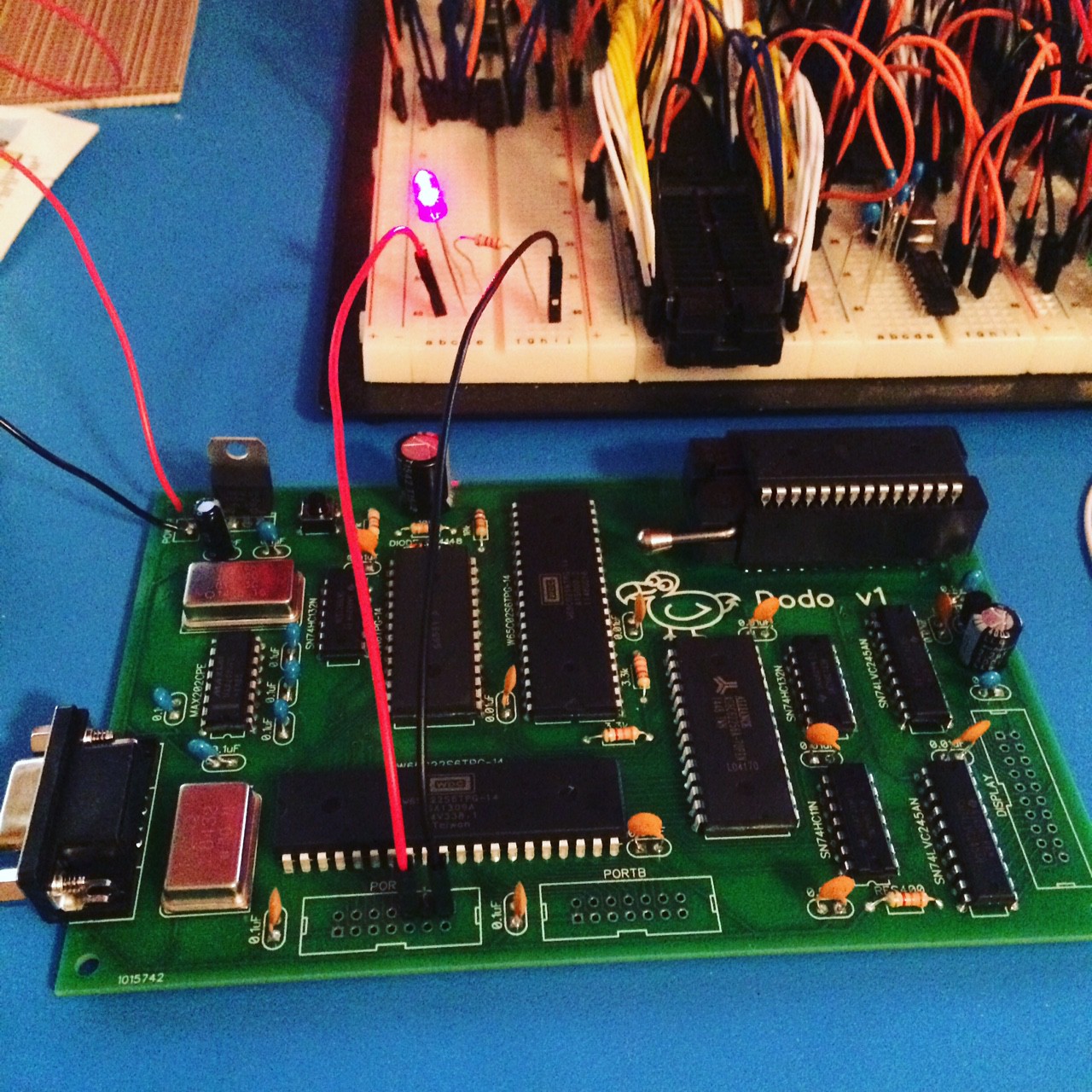
02/15/2016 at 17:50 • 0 commentsThis past weekend I assembled the board. Surprisingly, it only took a few hours. Even more surprisingly, it worked on the first try. The only hiccups were getting all of the correct components together. Digikey sent me the wrong capacitors, so I had to run out to Fry's to get the right ones. I also could not find my IDC headers... it turns out they were in my car the whole time. Tonight I might be able to test the display.
The first test was just getting an LED blinking, which tests about half the chips on the board. I still need to test the UART and the display. Also, I have all of the interrupt lines wired on the PCB, which I never did on the prototype. I guess I like to live on the edge, hopefully it will work!
![]()
-
The Boards Arrived!
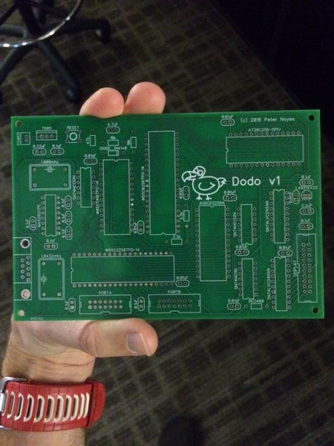
02/12/2016 at 16:45 • 0 commentsThe boards arrived and they look good. I ordered them from Bay Area circuits using their 3 board special which worked out well because each board pretty large at 24 sq in. To top it off, they sent 4 boards instead of the 3 I ordered! I will definitely go with them again. I can't wait start assembling!
![]()
-
Screen Testing
02/04/2016 at 17:47 • 0 commentsWhile waiting for my PCB I decided to go back and experiment more with the prototype. I wrote a program that should draw a vertical line that moves across the screen. In the video you can see a few problems. First of all, the line is flashing. Interestingly though, there are a few pixels that are not flashing. 8 of them to be exact. Does this mean that 7 out of 8 of the data lines are flaky? I will wait until I get the PCB back to see if this is still an issue. The second problem is that it is just not fast enough. Currently, I am buffering the display in a 1k block of memory, and copying the whole block to the SSD1305 chip for every single frame.
To improve the frames per second, I will adopt a strategy of only copying dirty regions to the display. I plan to write some routines in assembly to deal with sprites, and keep track of the portions of screen that that dirty as they move. I will also introduce the concept of "playfield graphics", inspired by the Atari which will take care the game background and surroundings. I will support 8x8 tiles for the playfield which will be very quick to copy around to compose the image.
-
PCB
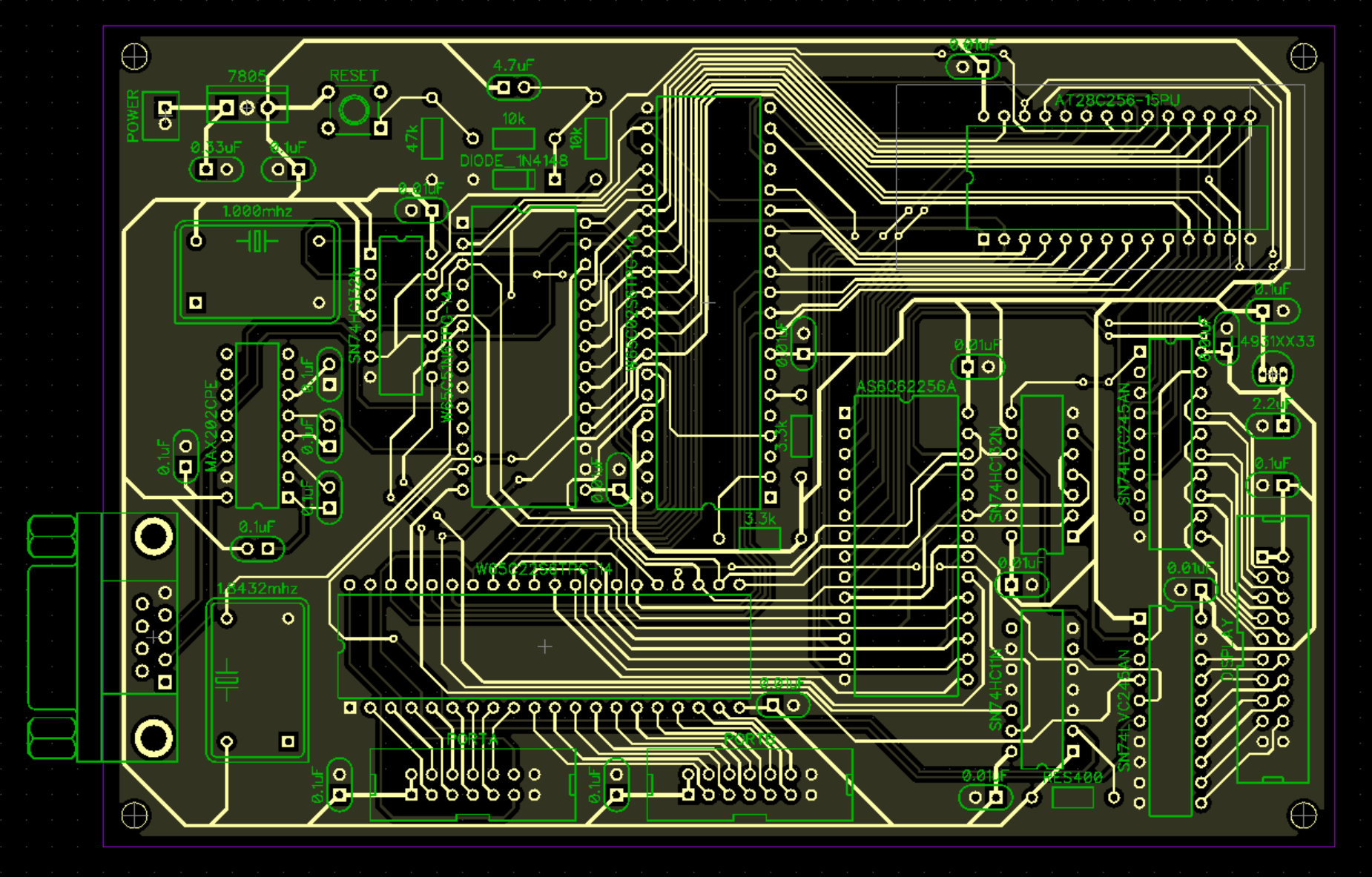
02/01/2016 at 05:08 • 0 commentsSince the last post I spent a few nights working on software, but I came to the realization that the board is a bit too flaky to develop on. Every now and again the board just doesn't work, but then I press down on different areas of the board and it magically springs back to life. Rather than spend hours trying to debug a rat's nest of wires, I figured my time is better spent at this point getting the design onto a PCB.
Thankfully, as I built the prototype I kept track of all my changes in a schematic in DipTrace. I now have that schematic layed out as a PCB in DipTrace as well. This is my first PCB design ever which is one of the reasons I took on this project in the first place. It was pretty fulfilling to get the last trace routed. I have some finishing touches to do such as put some pin numbers on the silkscreen. I hope to send the design to the manufacturer within the next few days.
![]()
-
Current Status
01/25/2016 at 17:49 • 0 commentsAs of January 2016 all chips are tested on the bread board. I can communicate over RS232 at 19200 baud. The display is working but I have not yet tested how quickly I can render. I am just starting to experiment with writing in C using cc65. To date, all code has been writing in assembly using ca65.
Next steps:
- Figure out sound. Options are to experiment with somehow using 65C22 to generate PWM signal, or perhaps buy a vintage sounder generator chip online.
- Potentially go with 2 VIA's
- Finalize schematic so I can layout PCB