 Tobias
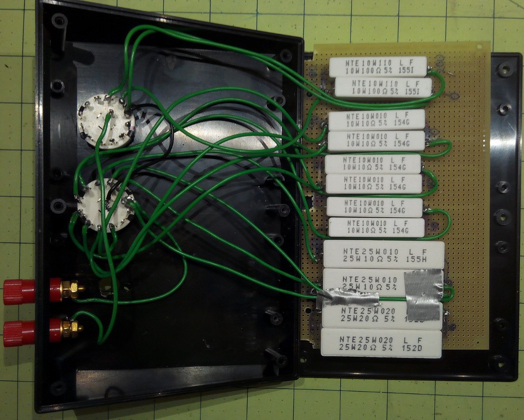
This resistor decade box can be set to a resistance between 10 and 290 Ohm in 10 Ohm steps (up to 990 once I solder in the remaining resistors). Initial tests turned out that single-digit Ohm values were not useful for my solar panels. Here is how I determined the wattage: If the panel can give out 20 Volts max. and in the worst case, has no own resistance, what is the wattage coming through the resistors?
| Resistance | voltage | power W |
| 10 | 20 | 40.00 |
| 20 | 20 | 20.00 |
| 30 | 20 | 13.33 |
| 40 | 20 | 10.00 |
| 50 | 20 | 8.00 |
| 60 | 20 | 6.67 |
| 70 | 20 | 5.71 |
| 80 | 20 | 5.00 |
| 90 | 20 | 4.44 |
| 100 | 20 | 4.00 |
| 200 | 20 | 2.00 |
| 300 | 20 | 1.33 |
| 400 | 20 | 1.00 |
| 500 | 20 | .80 |
| 600 | 20 | .67 |
| 700 | 20 | .57 |
| 800 | 20 | .50 |
| 900 | 20 | .44 |
On the first line, two 20 Ohm, 25 Watt resistors in parallel give 10 Ohms with maximum 50 Watt which is above the required 40 Watts, etc.
Why resistors? a) cheap b) easy to understand c) no power supply required, good for outdoor testing.
Discussions
Become a Hackaday.io Member
Create an account to leave a comment. Already have an account? Log In.