Arya
Arya-
Case limitations
09/23/2016 at 19:24 • 0 commentsSo, I've got all the necessary components:
- 2 Hanrun magjacks for Ethernet functionality
- Mini PCI-E modem for 3G
- Mini PCI-E to USB breakout with SIM slot
- HC-SR05 ultrasonic sensor
- A small flash drive for extroot&storage
I've actually been using this router for a couple of months. The limiting factor, however, was that I didn't manage to make it both create a network and connect to one. Thus, it was useless, though functioning. I also managed to re-design it a couple of times, making it a little nicer each time. However, it still needs to be finished.
I've tried to make one more attempt with making MagJack breakouts, essentially, SMT-deadbugging all the passives onto the jack itself and making a small 3D-printed insert to hold it all in the place designed for it. The insert turned out to be OK, however, the result turned out ot be horrible - the case wasn't meant for that, that's for sure. In the end of my tinkering, it just broke and that was the end of my efforts for that day.
So far, the case has been a nice limitation. However, it's time to remove it from the equation by... Drawing the exact same case in 3D and printing it, with all the holes and necessary features done already. It will also make the project much more repeatable (save for the fact that it uses a devboard that's impossible to get from anywhere nowadays). This could also be an excellent opportunity to try one of those free CAD packages.
Stay tuned~!
-
Why existing power management sucks
02/05/2016 at 16:42 • 0 commentsHi!
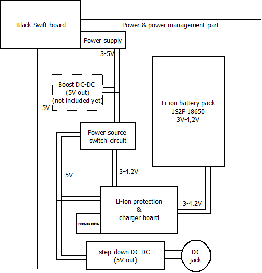
Today I'm going to tell you about Alice's power management and power structure. As for today, it is like this:
![]()
It's pretty simple and mostly made of ready-to-go modules. This is one of my beliefs - projects like this are better if they're modular (modules are presumed to be easily available though). This reduces human error, decreases total effort necessary to build the thing for all the others and can serve as a learning material. In this case, I'll try to ensure this is a good learning material for anybody that'd like to build his own thing - or maybe even replicate my project. Now, with these intentions in mind, I'll start describing what I've constructed.
Description
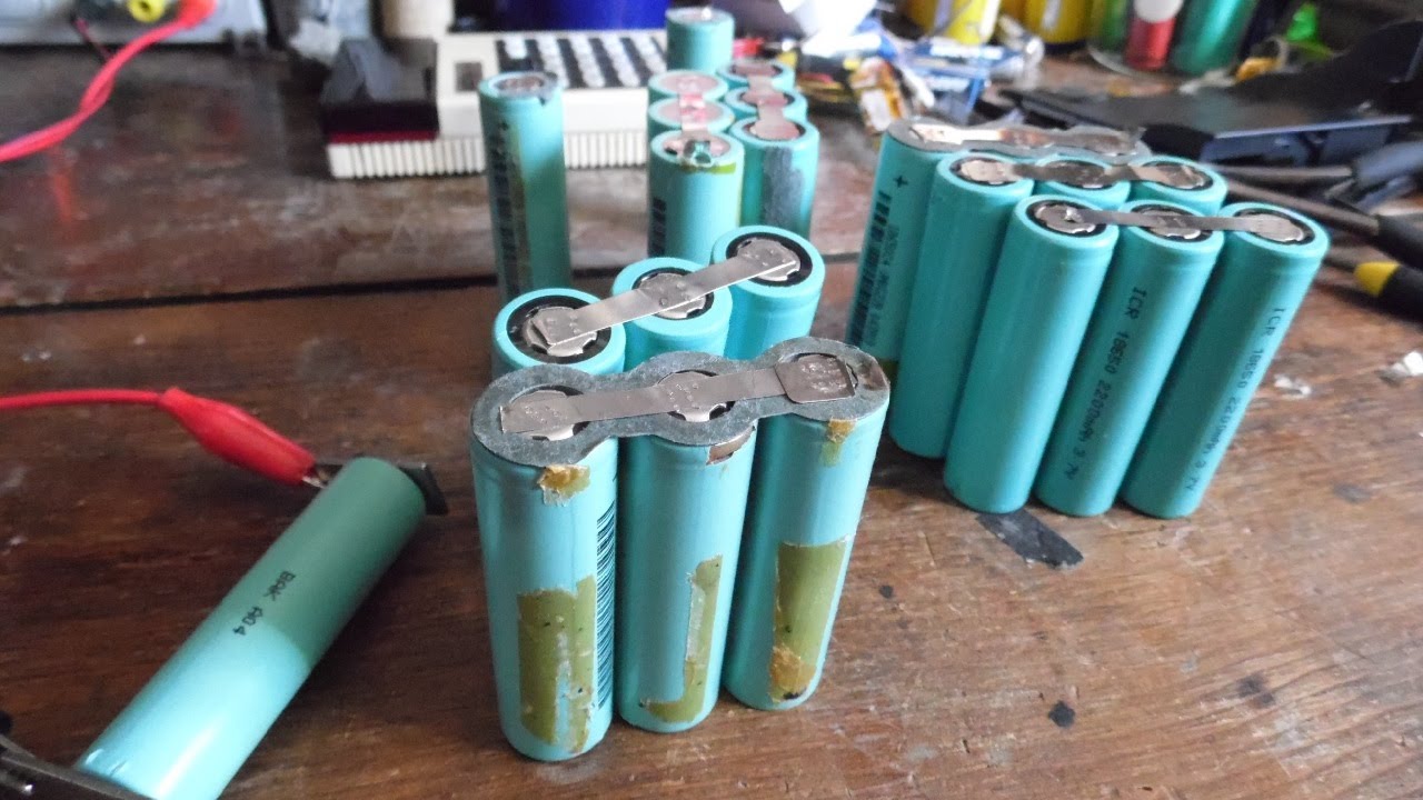
First of all, Lithium-ion batteries. This is an excellent power source, not as scalable as others but you can build your own thing pretty easily. Research is the key though. Once you know, i.e. that you can't simply hook a Li-ion cell to a PSU to charge it, what PCM means and what it protects from, as well as acquire all the components necessary, there's one more widely available type of power source in your arsenal. For Li-ion, there's still a lot of theory behind not burning your house, so DO YOUR HOMEWORK BEFORE.
![The magnets trick is a nice one.]()
I've got a lot of 18650 elements from laptop batteries, so I've decided to make them hot-swappable in addition to being chargeable while in the device. This way, I can minimise downtime in case of batteries getting flat and no power source being nearby - I tend to carry 18650 cells with me, as this isn't the only project powered by them =). The case limits me to 2 18650 cells, and 2s1p configuration would be tricky since I need balancing for charging them in a way other than out of the device - I don't have any balance charging modules that'd be as easy to use, and I couldn't use 5V to charge the battery without overcomplicating my setup, so paralleling cells is the way to go.
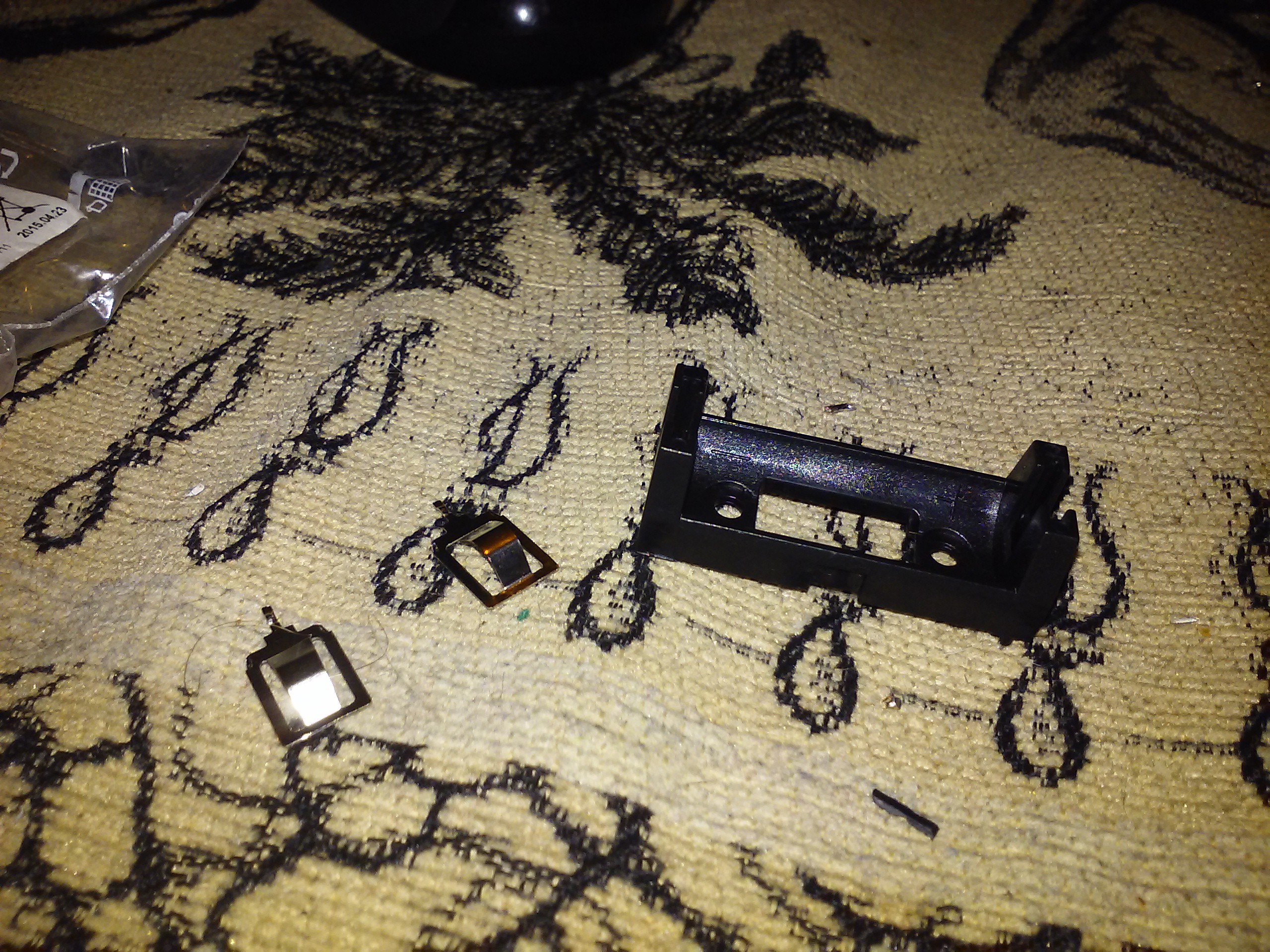
I don't need to (and I really shouldn't) solder wires to the batteries, so I needed a holder. However, all the pre-made holders are either bulky, expensive or both. I've made my own holders before, all you need is 2 pieces of metal - and a way to hold them tightly against the battery poles. Now I advise against these spring-loaded contacts you typically can salvage out of cheapest battery holders if you don't have a really tightly packed enclosure in which they can be securely fixed. In other words, don't use them if at least one of your contact groups has at least one axis of freedom.
I've bought a battery holder with nice flat yet strong contacts (spring-loaded also take more place) and embedded them in my case with hot glue and a couple of wires. Simple and takes less space than anything you can buy.
![A CR123 holder, AKA the only one a local shop had that had this type of contacts and wasn't too expensive.]()
![]()
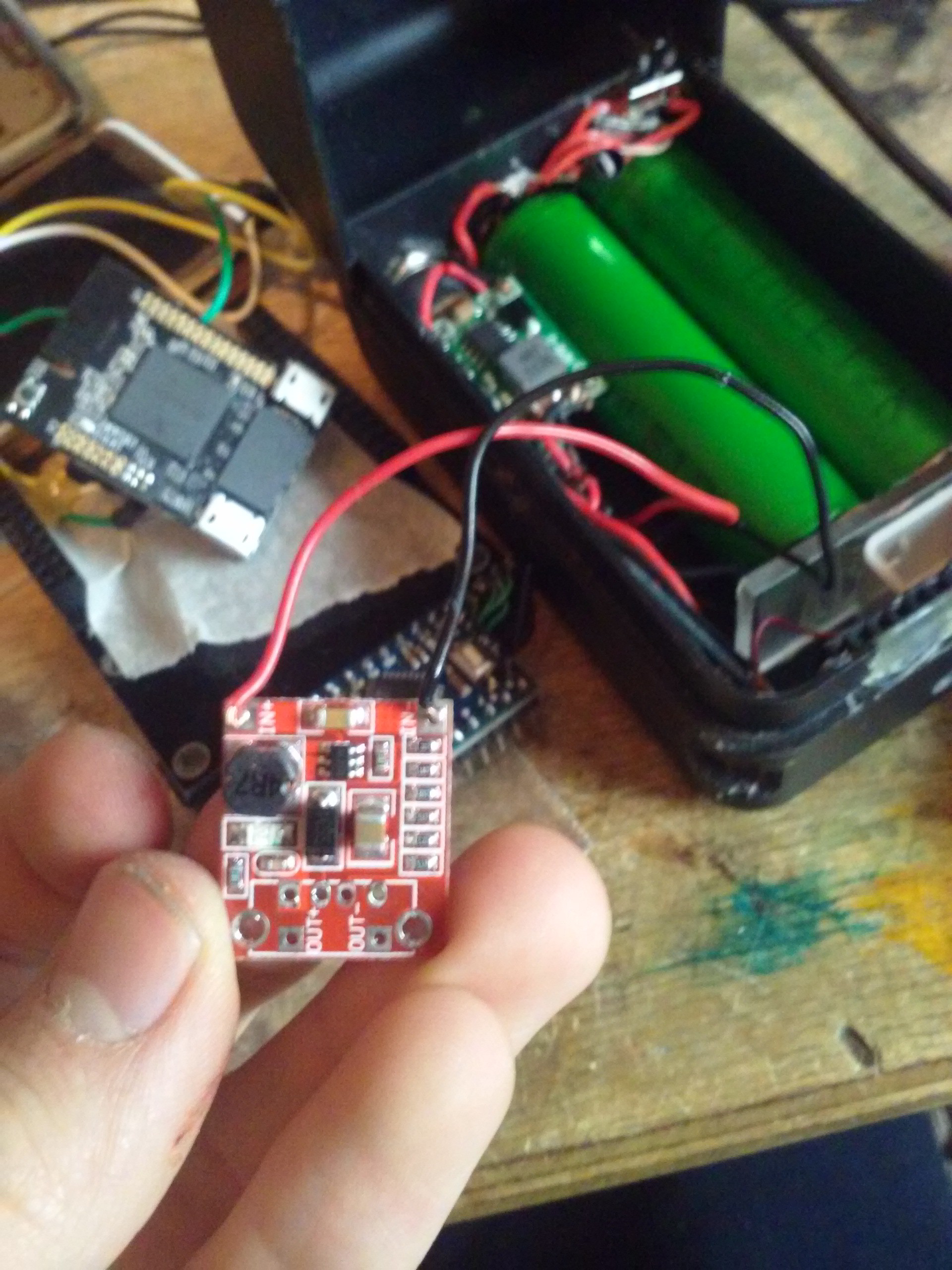
For charging and protection, I'm using the following module:
![Disregard "5V-", it's GND. Battery GND is not GND, though, it goes through the protection module, so you shouldn't short it with GND.]()
Charging+protection module based on TP4056 IC. It's a linear Li-ion charger, only meant for 1sXp configurations and capable of handling no more than 1A (current configurable with R3), but that's enough for me since total capacity is about 3-4Ah (they've been salvaged from a laptop battery, after all). I also don't mind the heat issue, it doesn't have much heat-sensitive components around. It takes around 5 hours to charge from totally discharged batteries to full charge.
There's a difference between a module with protection and without. If you're building a simple charger and there's no consumer of the battery connected to it, you should be OK with an unprotected module. If it's a device, you want the cell protected so you get the module that includes protection. Both are useful so I try to keep enough of both types for all the chargers and devices I might build.
Once that's sorted out, we need a power input for charging. Since I've already defined that it needs to be 5V capable, there's a MicroUSB socket sticking out the case which, conveniently enough, is the socket on the charger board - I can simply make a hole for it, so that's what I did. It's in parallel with the IN pads on the charger board, and in parallel with the 5V input rail.
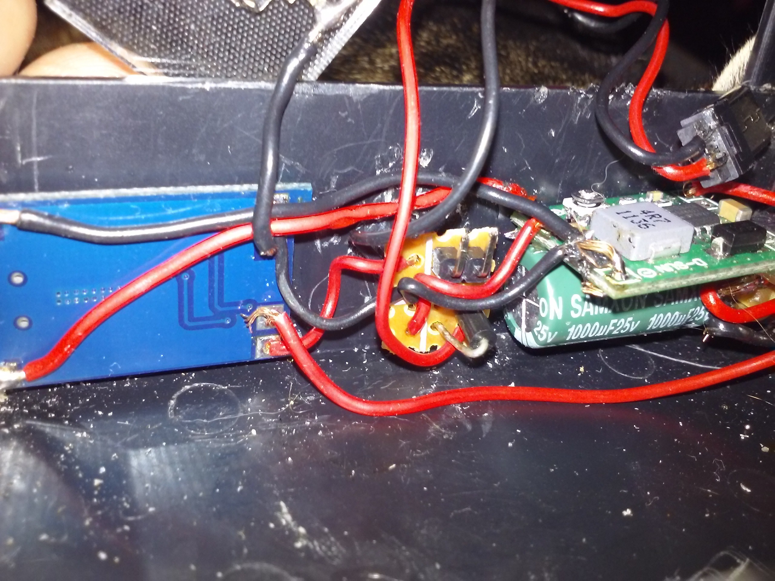
Also, as a feature, I have a switching DC-DC that will make the device be able to feed off various router PSUs. The more you are independent of the power sources, the better, so if I can use somebody's laptop PSU or just unplug the nearest TP-Link, that'll be great. The capacitor is rated for 25V, and the Vin max for DC-DC is 28V, and most power sources are in the safe zone. There's not enough protection on the input, though - that's bad, since it doesn't deal with reverse polarity and the cap has all the chances to blow up if I accidentally get a PSU with a different polarity. It's to be improved - most likely, with a MOSFET. Alternatively, with a plastic insert that shields all the circuitry inside from the capacitor's blast. Depends on the level of my laziness.
![]()
![]()
The 5V rail powers the charger, as well as the board while the battery's charging... Ah, about that.
The power source switchover part i the part where I've learned something neat while building, and for that I'm thankful to the #Hacker Channel. This is the trick with switching power sources from battery to USB when the USB is available. Why'd I need that? Simple, you shouldn't drain the battery while it's charging, otherwise it won't get the charging current as the load will be taking some. Not only that means slower charging, it also means that you'll never charge the battery completely as the current decreases over time near the end of charging, and at some point it's definitely gonna be on par with your load's consumption.... Also, why the hell you'd use any of the battery power when you've got a 5V source available? That's just crazy! So, I've made a circuit with a relay first:
![]()
That's the way I've posted it to the Hacker Channel, understanding it has to be overkill (relays are huge and I've never seen one in a mobile phone). I've received a couple of suggestions and kept them in mind. I've soon understood while testing that the relay scheme has a major problem - there's no power to the circuit while the relay's contacts are "in flight", and the AR9331 rebooted every time I'd plug the MicroUSB in. The online calculator said something about the capacitor's value that I'd need to power the circuit for the tough power switching times, and after estimating said capacitor's size, I've understood I might need a bigger box for the project to use relays, and een more if I want to have 3G connectivity. I've had to scroll through a week of chat logs.. Shame it doesn't have search!
![One more problem - the relay is huge.]()
![]()
The circuit (appnote from Microchip on this approach) has 3 components necessary for the switching itself one of which was a MOSFET. I never had any experience with them before, so I had to read some appnotes on that, namely that one was useful. They appeared to be very well-written, but didn't include the clever way the FET was used in the circuit proposed - 'the other way around', if you wish (the explanation isin the article).
Flashback to the days when I didn't have to knowledge which parts I can replace with which and when, so I was almost sure I had to get every part listed right, as well as would be very confused when the BOM would say "any NPN transistor". Same with FETs - the knowledge on their usage can save you quite a bit of time, certainly more than just the ability to google around.
Anyway, I found the FET that was both suitable for the task and available locally (IRLML6401, if you're wondering), built a breadboard circuit to test everything... And got 250mV drop between drain and source while on battery power (so, a drop on battery-to-board path) which at 200mA is comparable to a Schottky in the same situation. Long story short, I decided to solder it onto a protoboard to at least make it permanent, after that the Vds dropped to 8mV. Lesson learned - not to trust breadboards too much. Or maybe it was wires. The breadboarded circuit is long gone, all that's left is lack of trust in breadboards and a jumper header between Vout and Vbat on the source switch board, in case I wanted to override the FET manually when I knew the power source wouldn't be connected (200mV is too much of a loss when you're squeezing out every minute out of the batteries and your voltage is around 3.7).
I'm sure this jumper would be a disaster to forget in the circuit if I were to connect 5V . I wonder if the protection circuit protects from 5V applied externally on battery's contacts, maybe some day I'll go to a forest nearby to test... I'd also gladly charge some certainly dead batteries - I like fireworks. Not to mention that I want to get some lithium fire extinguishing training before I get that unexpectedly... Batteries are complicated and dangerous.![A soldered prototype - I love mixing perfboards and SMD.]()
With the switchover circuit, the output we're getting will be from 3 to 5 volts with enough amperage to run the board (I haven't attached other parts of project like 3G or AVR yet, but it should be sufficient). The board is OK with voltage down to 3.2V, which should be plenty - there's an LDO and the CPU voltage s 3.3V. If there's a problem, I'll probably just power the board through a boost converter...
![Checking if it works at all]()
Which is definitely needed for USB devices I'll be using. What a shame USB VBUS is not 3.3V... But that's just me complaining, things can't always be perfectly suitable. Anyway, I've gotten a boost converter module from eBay, and I should get more because these things seem to be very useful overall, with all the Li-ions. Liions. Lions. Heh.
So what I'm saying is - the boost I got has stated 3-5V input, so it seems to be perfectly suitable for my application. I've yet to test its efficiency - as well as actual suitable voltage range along with current. Speaking of which, I also need to test the capacity of my batteries, as well as put all the components together and see how much they consume. I probably will have to make a simple setup with Arduino and serial data transfer... It's never simple. I'll leave that for the next article.
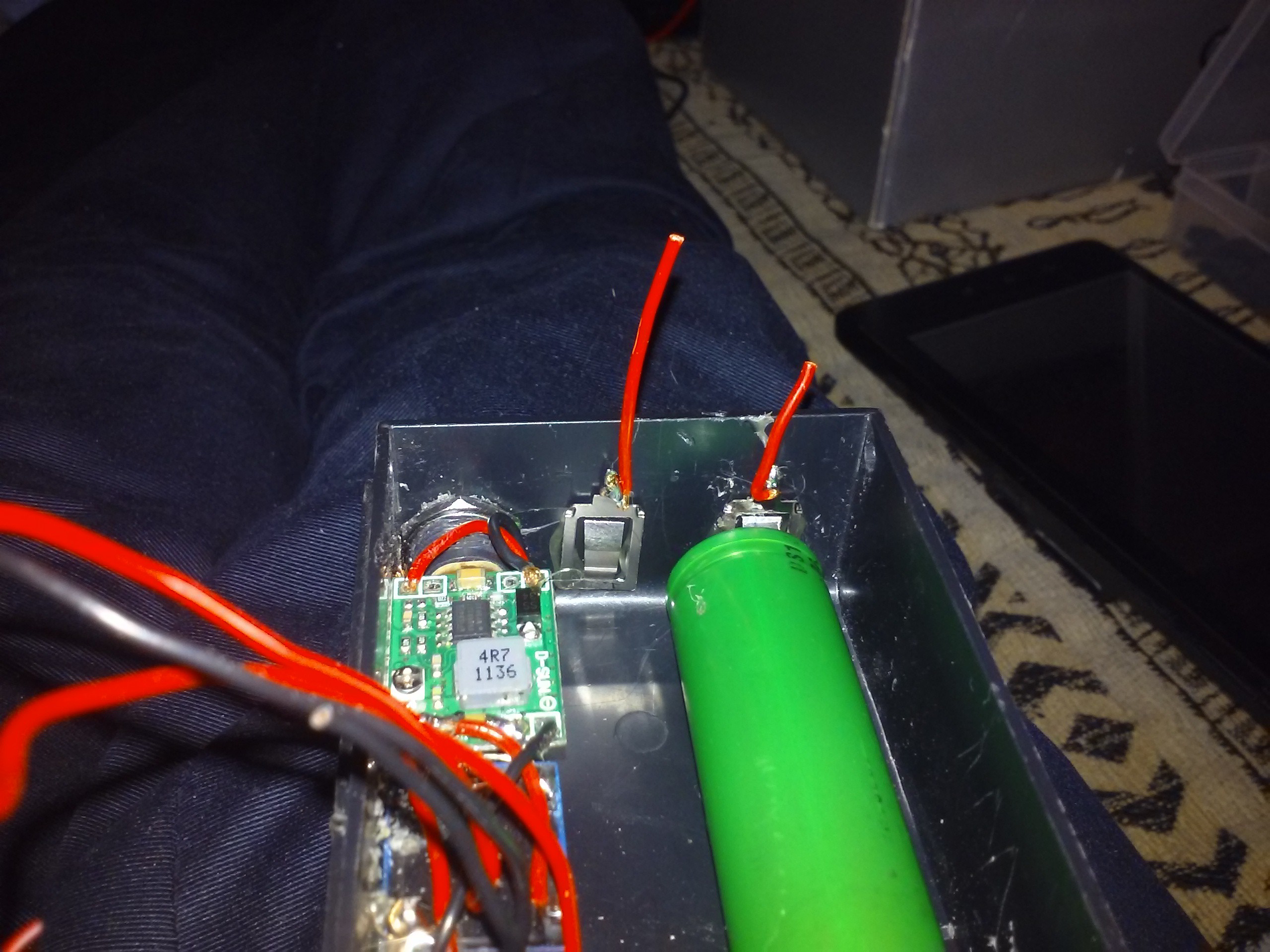
Here you can see a couple of photos with the individual components already mounted:
![Battery charger, new switchover circuit and the DC-Dc for higher voltages]()
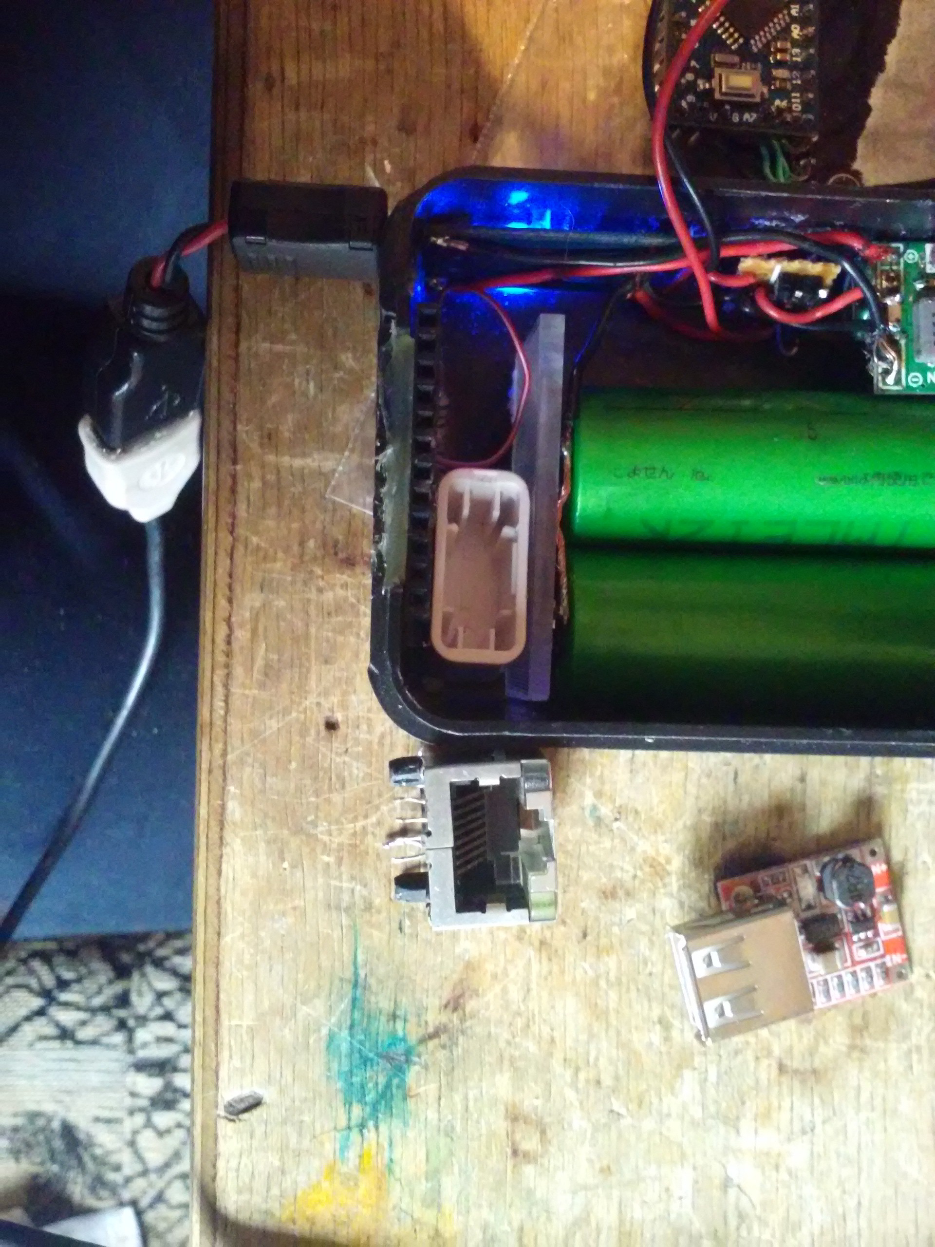
![Holding batteries securely in place with a flash drive cap]()
![Looking for a place to put an Ethernet jack at]()
Assumptions/shortcomings made at this stage, or why does it suck:
- Battery holder has no reverse polarity protection, and if you insert 2 batteries with opposing polarities (they're in parallel)... I'm not willing to try. I can add it though, I think. Maybe a PTC or two with diodes (link) will suffice, and they aren't that large.
- Same goes for DC-DC. Not enough protection on this, and it would benefit from that - it's a barrel plug input, after all, there are all types of horrible voltages we can get out of a barrel plug, i.e. 48V AC
- There are 2 possible 5V inputs but no circuitry to protect either of them from anything... Maybe the DC-DC has a diode on its output or something, but certainly not the 5V port.
- There's no power source manual override or something like that, it cannot yet pick power paths as it sees fit. There's also no power monitoring yet - it's yet to be added. On the other hand, it won't ever complain about "charger not suitable/resistors on data lines not good enough" (yeah, it'll just blow up happily) (those vendor lock-in jerks though) (I don't like adding an IC to my self-made 5V chargers just so that some stupidphones like them)
- I want to up the barel jack power input range to 25V, I guess I'll meet some 24V adapters sooner or later. It also needs a fuse.
- It's still a mess of wires, given that I've remade it from the relay-driven switching to use a FET, and the wires are not in their best condition from soldering so many times.
- No big capacitors on the main power rail (the 3V-5V one). I don't know if I need them, I'm just so used to them =)
- It assumes that the 5V inputs will have enough amps to feed everything. I don't have a clue if this assumption is bad, and I don't know how to protect from undervoltage =(
Diagnosis - to be re-made to add all the protection missing, however good it looks or works. I've already ripped everything out, cleaned the boards, re-planned the wires and now it's gonna look nicer and work better.
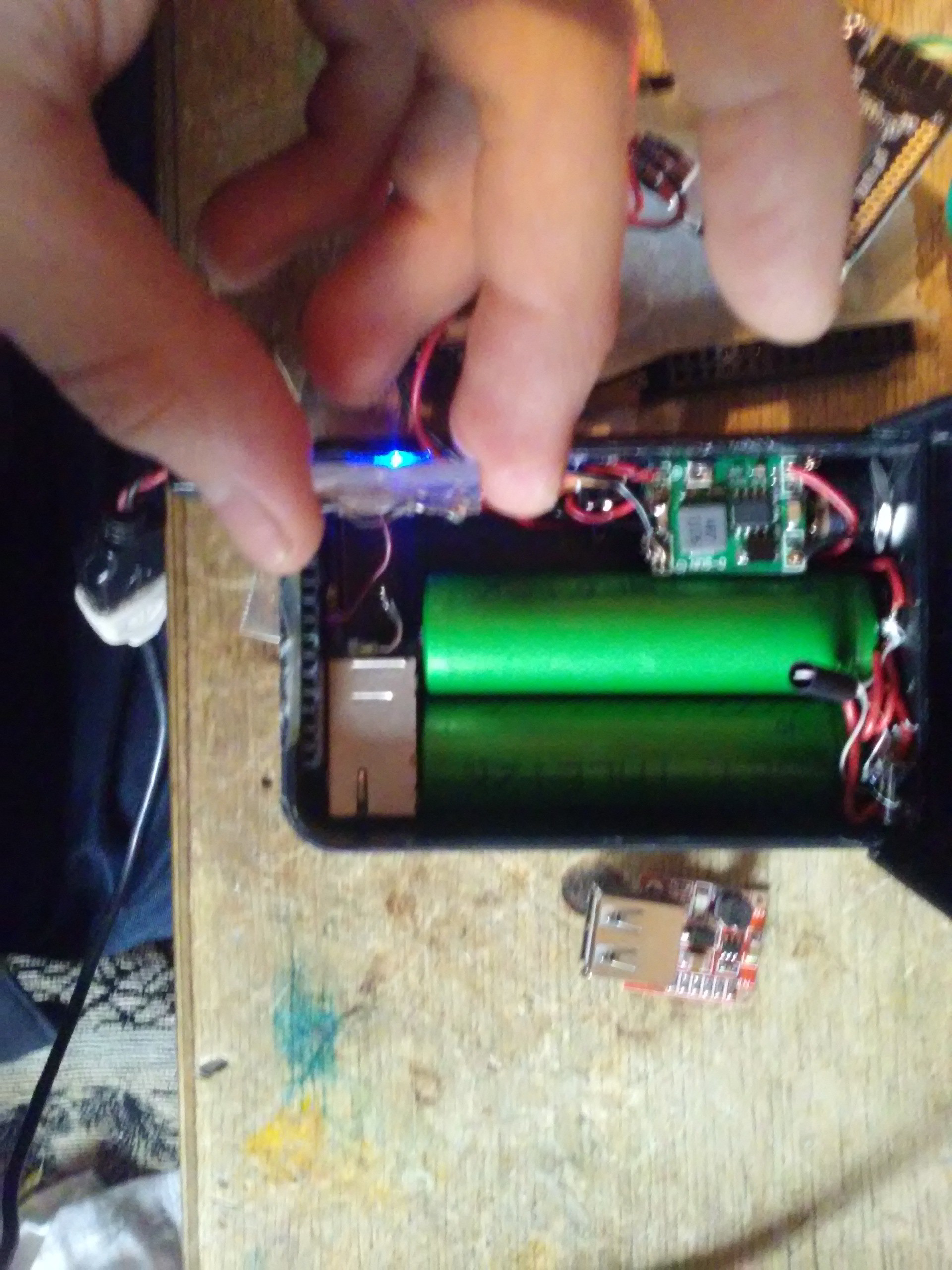
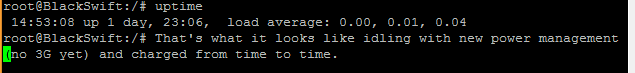
I'm getting a 3G modem soon and I'll be testing that as well =) Power path control might be introduced in the next version, this prototype doesn't need one. It will have power monitoring, and that I'm working on right now.![Making sure everything fits and thinking about what else can be inserted]()
![Logging the output of uptime command in a loop while on battery power]()
![Ditto - it topped at 19 hours]()
I'm sorry for the delay in the updates. I'll start writing the next article tomorrow =)
-
Announcement
01/28/2016 at 00:42 • 0 commentsWhat I'm going to do:
- Make a battery charging/monitoring/DC-DC setup that's not too complicated and yet safe to use with Li-ion - in progress
- Assemble the thing. Write some sample code, as well as Arduino firmware test.
- Set up Python on my board and do some benchmarks to understand whether it fits the board and whether it works fast enough.
- Make some user-friendly scripts to automate things, such as USB auto-mount with additional actions, SMB/NFS share creation for new partitions, printer hotplug and so on
- Automate some time-consuming repetitive tasks, such as uploading packages and firmwares on the board for testing
- Learn to assemble my own packages and firmware binaries, try to support the infrastructure for other users, too
- Try to set up IR receiver on GPIO with LIRC - this was a big struggle for me when I last tried doing it with OpenWRT, I wasted a couple of days
- Assemble and test SPI flash programmer prototype which uses Raspberry Pi, it can be used for ISP on Pro boards and programming of desoldered chips of Basic boards - just in case I mess up the bootloader =)
- Try to learn some C/C++ writing drivers for stuff I'll be connecting (I've always got Python in case driver writing appears too complicated =) )
- Later, make a new hardware revision with more electronics on a custom-made PCB, more batteries and a better case, preferably wearable on a belt, though not necessarily.
Here are some photos to show you what it looks like now with power input and management stage in the making, finished and re-made again after finding some problems:
![]()
(Masking tape to be removed soon)
![]()
- Make a battery charging/monitoring/DC-DC setup that's not too complicated and yet safe to use with Li-ion - in progress
Personal portable 3G router
A battery-powered router with enough features to be unique. WiFi, wired, 3G+ anything I'll need from OpenWRT on it.