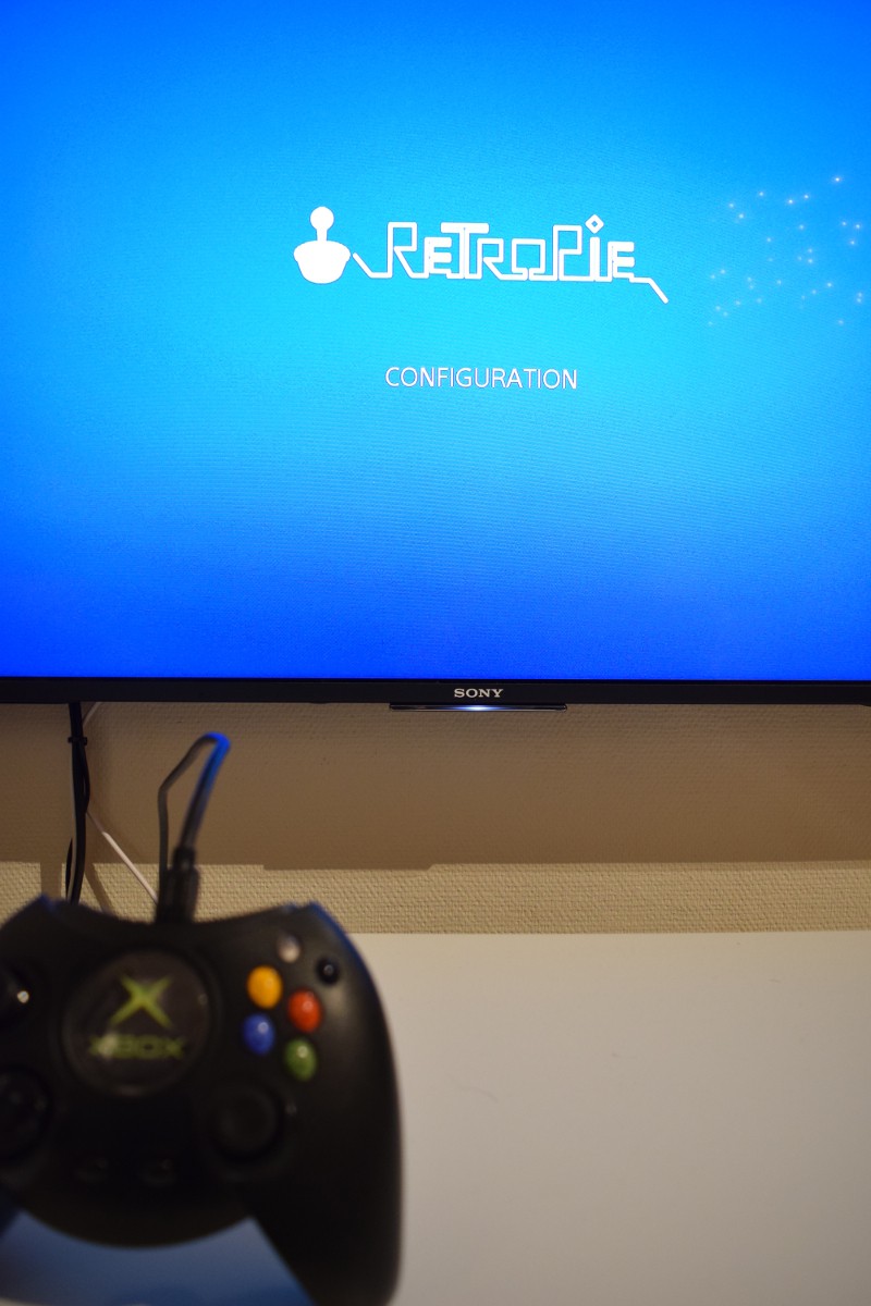
This is a mini project that uses some old hardware lying around at home to create a fun device that can play retro games or do some gamestreaming on the go only requiring a HDMI cable with or without USB charger.
The requirements for the device:
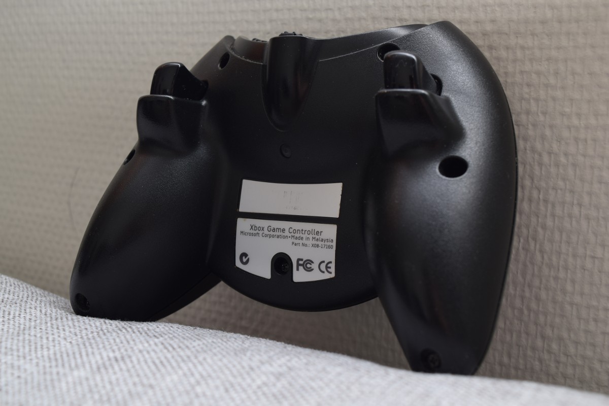
- Look as original as possible
The functionality that will be built in:
- On/Off button that boots and shuts down the raspberry pi
- Full input from the original controller with the OTG port
- IR blaster for controlling TVs
- 3000mAh battery with a Adafruit powerboost 1000c for charging
- (Coming soon) HDMI output
The images I have taken of the project so far:
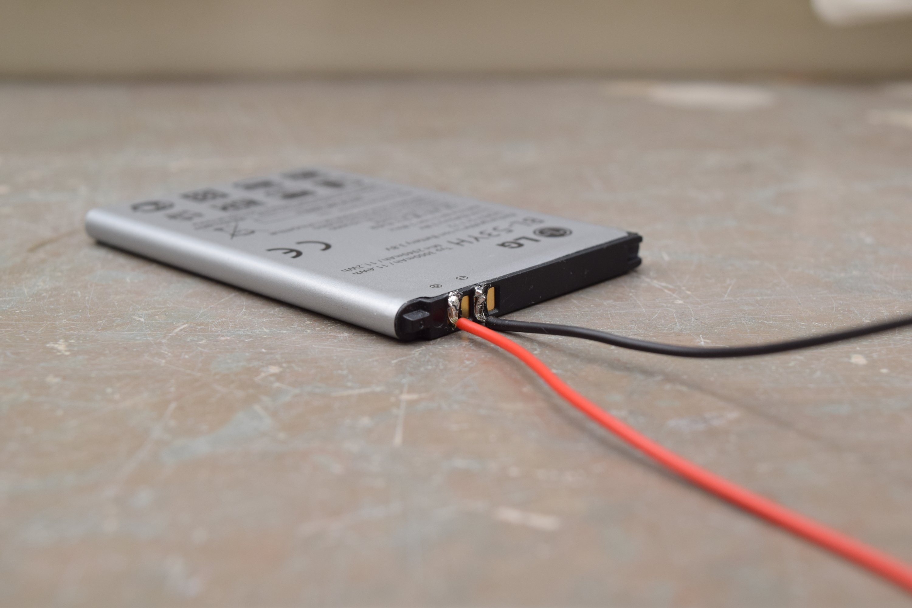
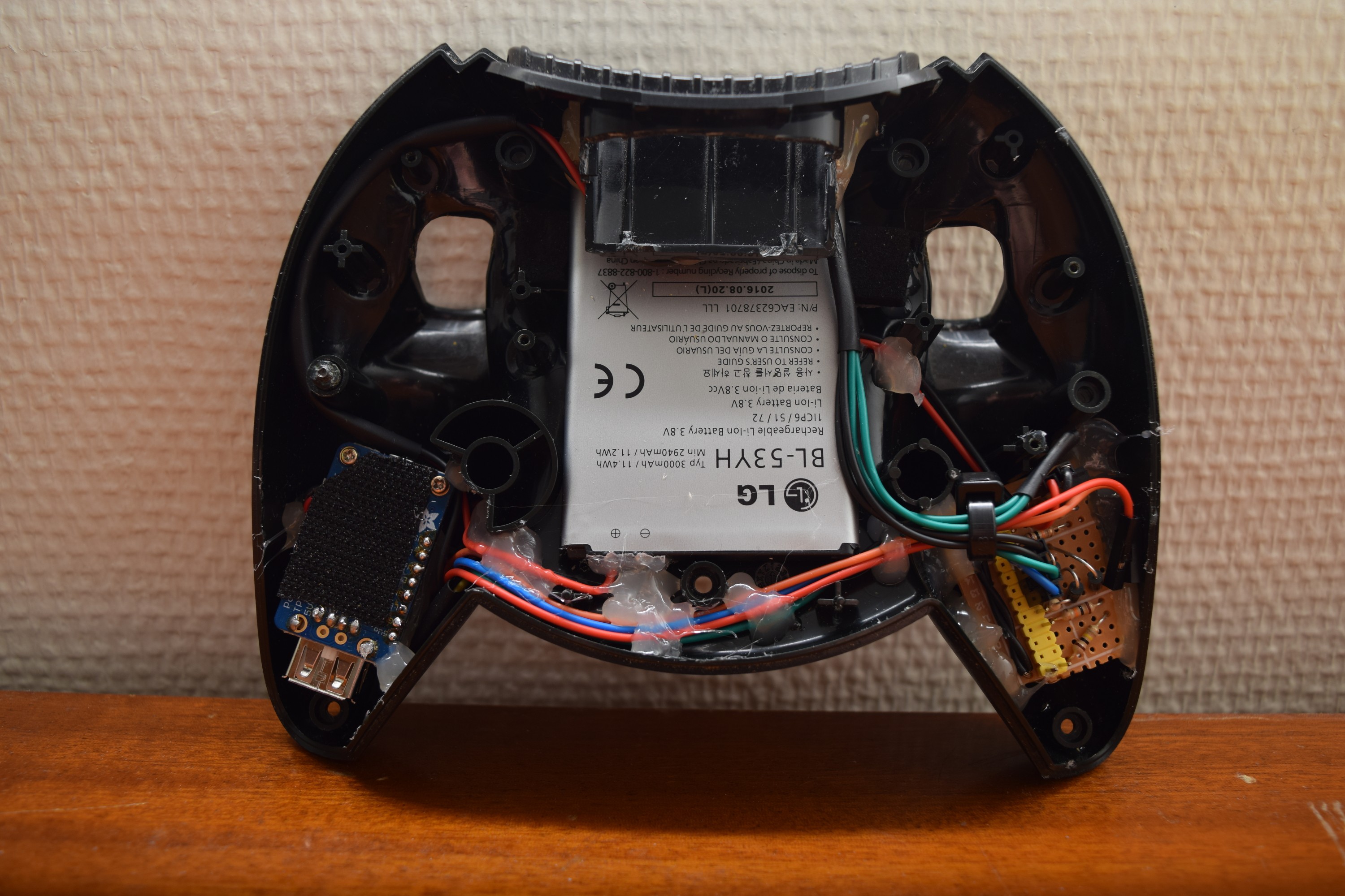
The battery used for the project is a LG G3 (BL-53YH) that I carefully soldered wires directly to the tabs:
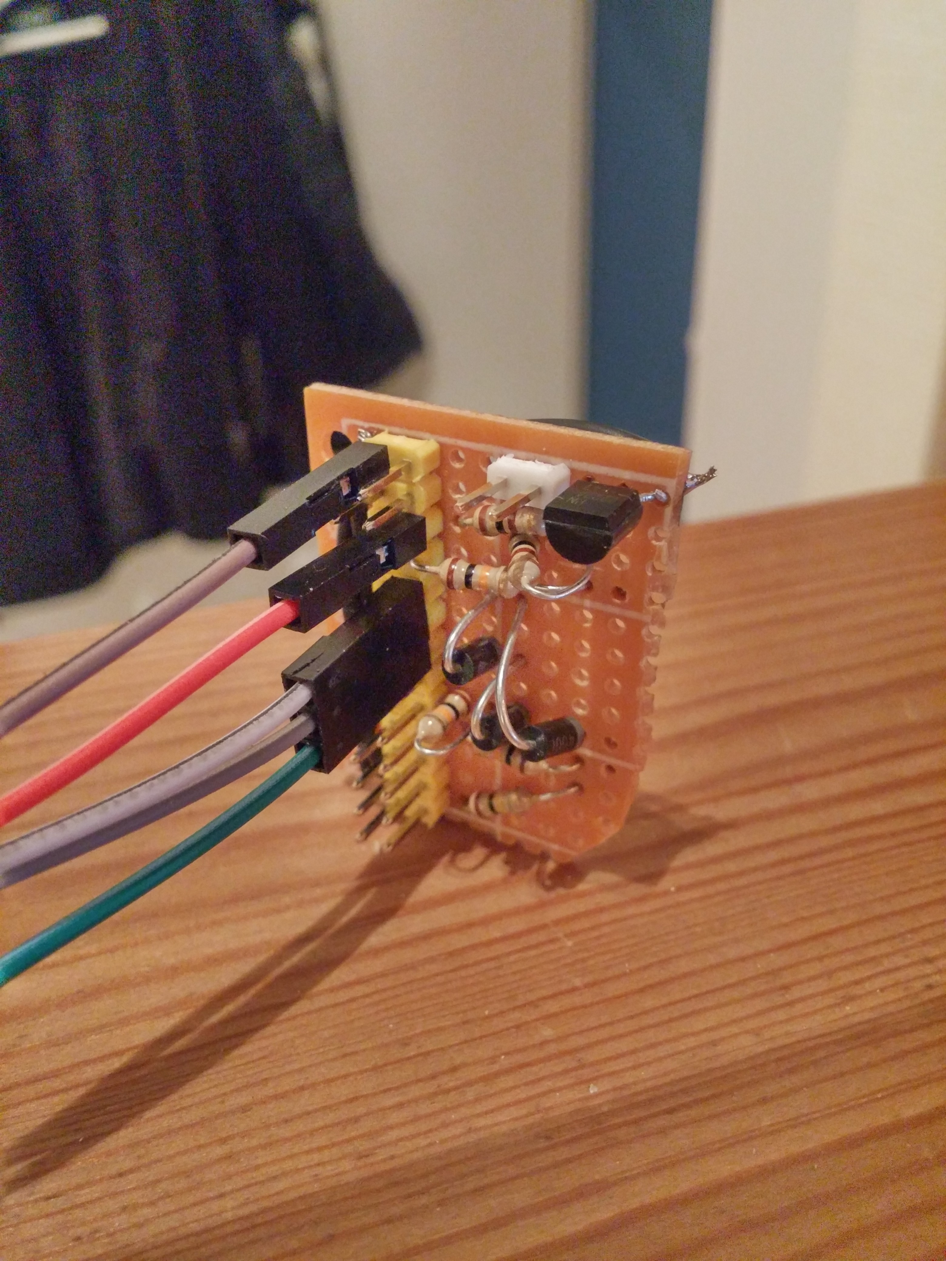
The On/Off functionality and IR circuit (aka a transistor and a resistor) was put on a pertinax board. This power up and down circuit was borrowed from the lipopi project and works really well:
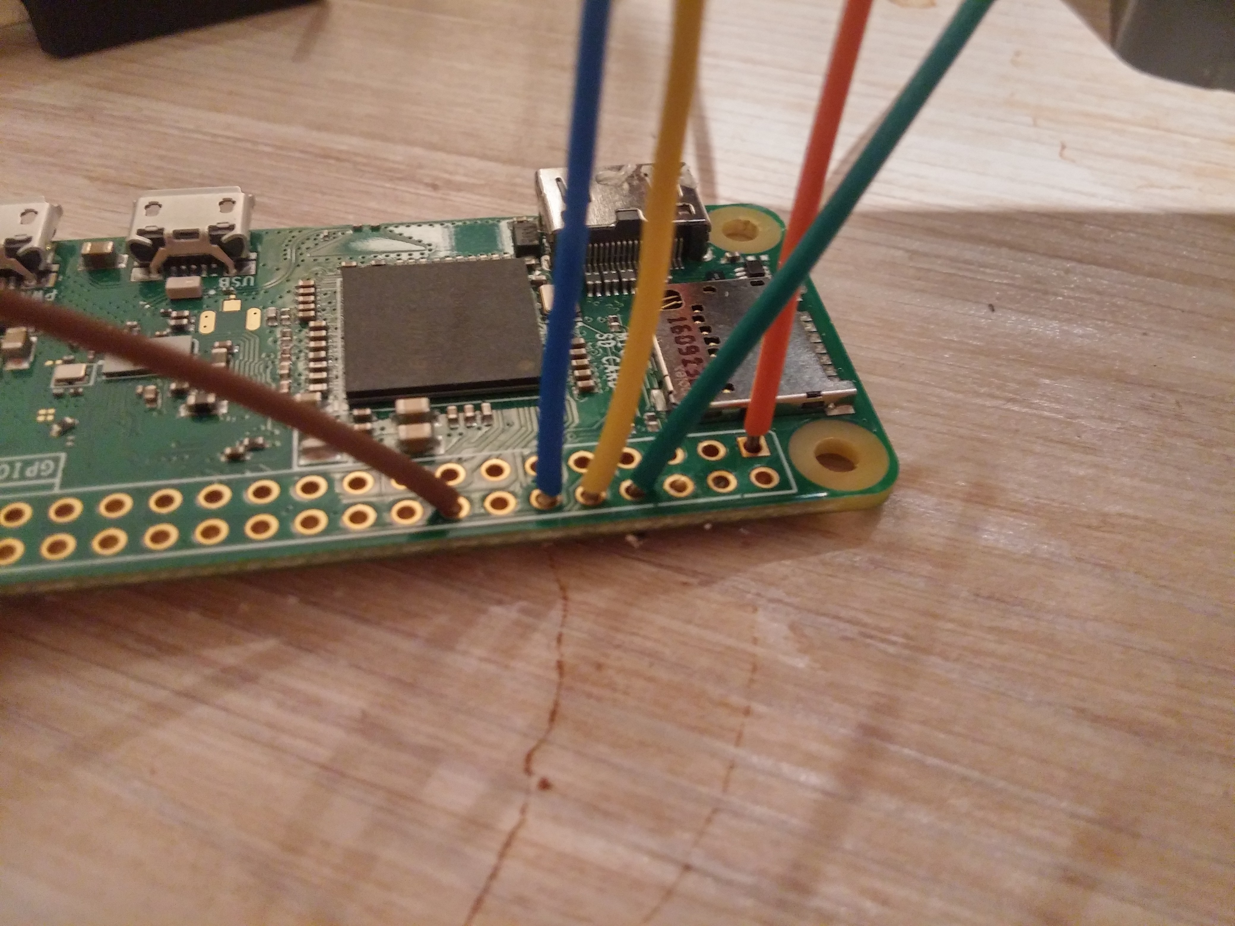
Also soldered wires to the raspberry pi to save some space instead of using headers:
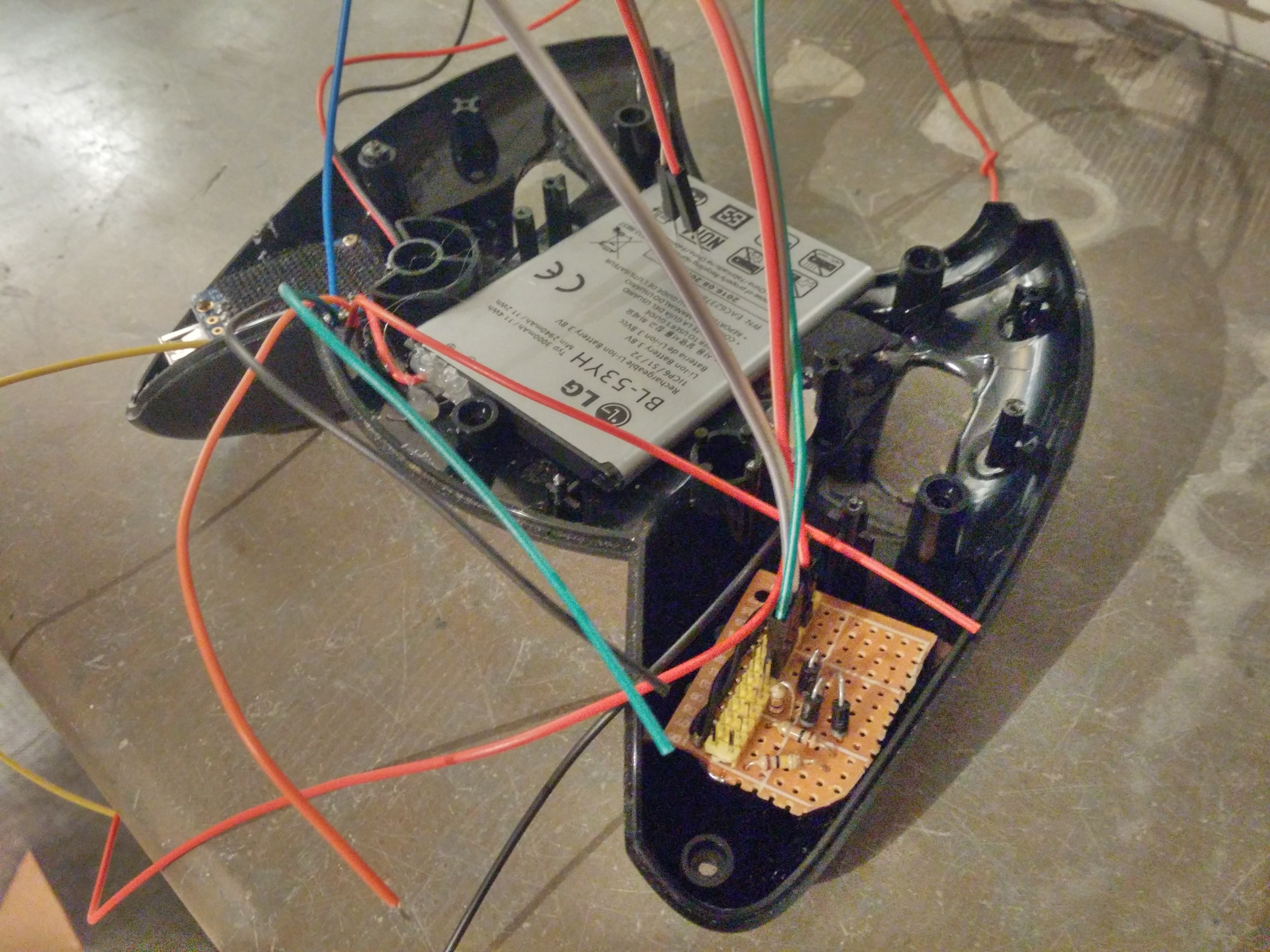
Tested out how the components would fit inside the case. The battery is a tight fit but with some case modification (using dremel and cutters) it then sits snugly under the original xbox pcb. Both rumble motors sadly had to be removed to make the powerboost 1000c and On/Off circuit fit but would probably have drained the battery too quick if used anyways:
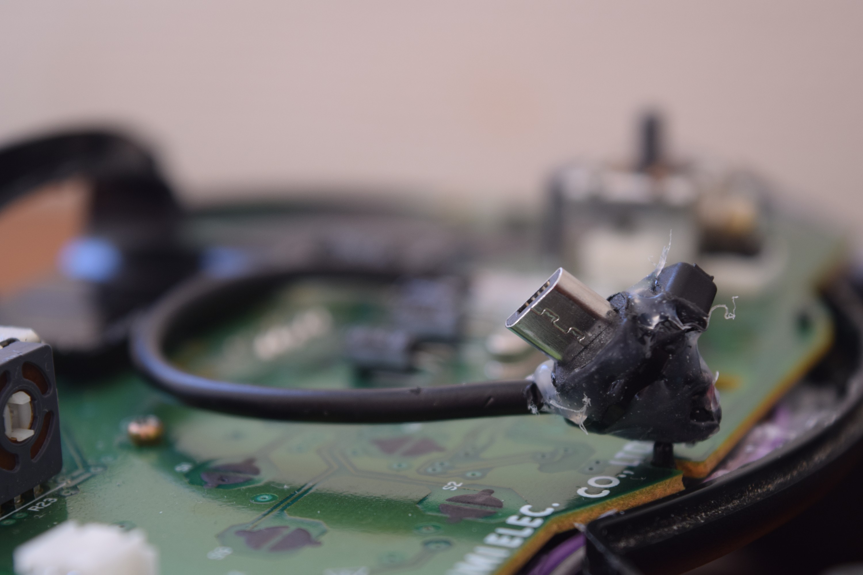
Soldered a micro USB connector directly to the xbox pcb where the cable otherwise would be connected (for those who does not know, the original xbox ports are basically USB), this extremely "home made" contact then connects to the raspberry pi:
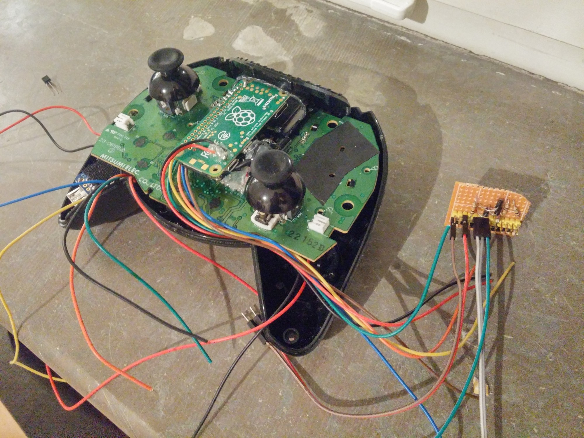
Tested a mockup of how the raspberry would fit inside the case. The duke controller has a lot of room inside but with all components and wires........it is a tight fit to say the least:
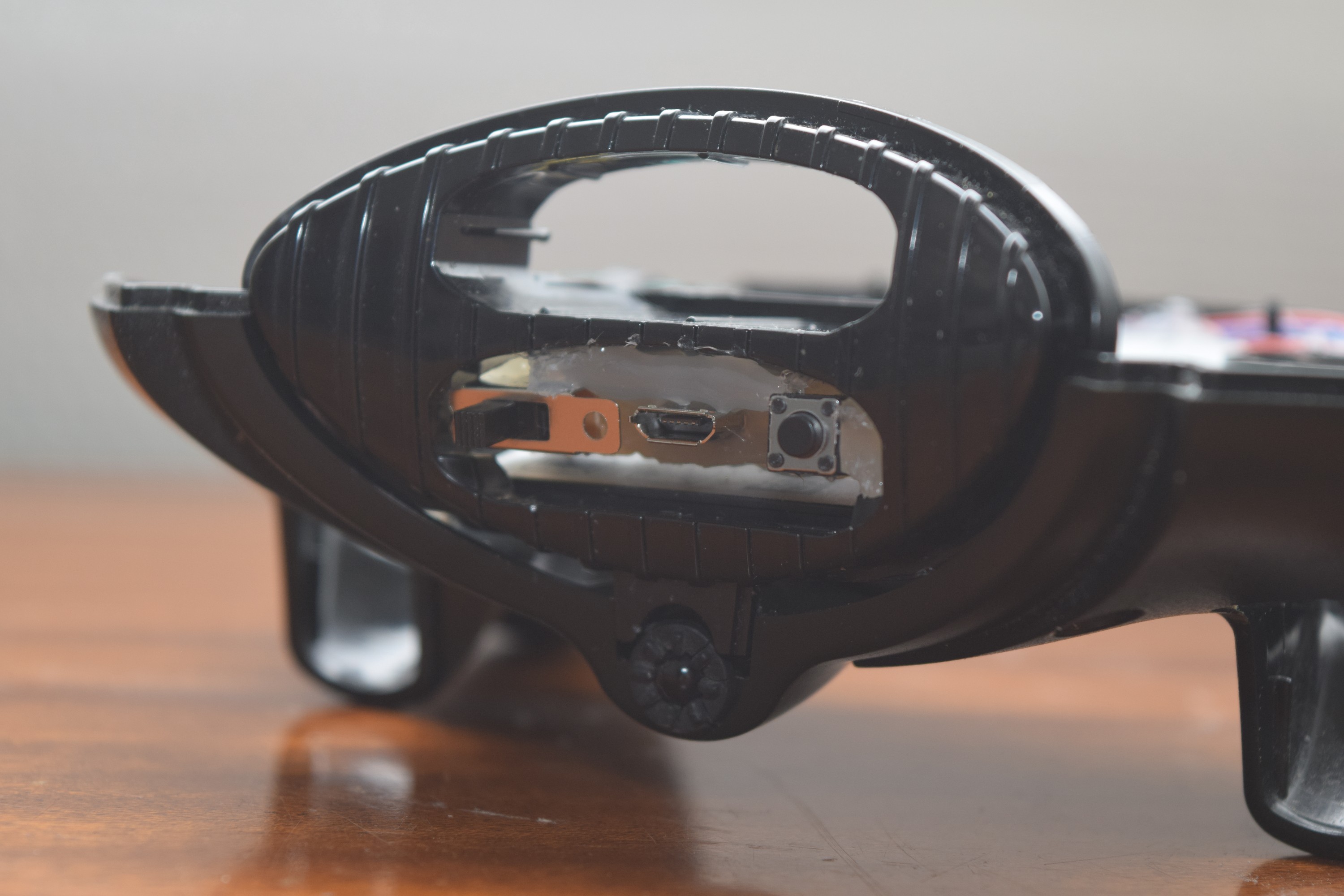
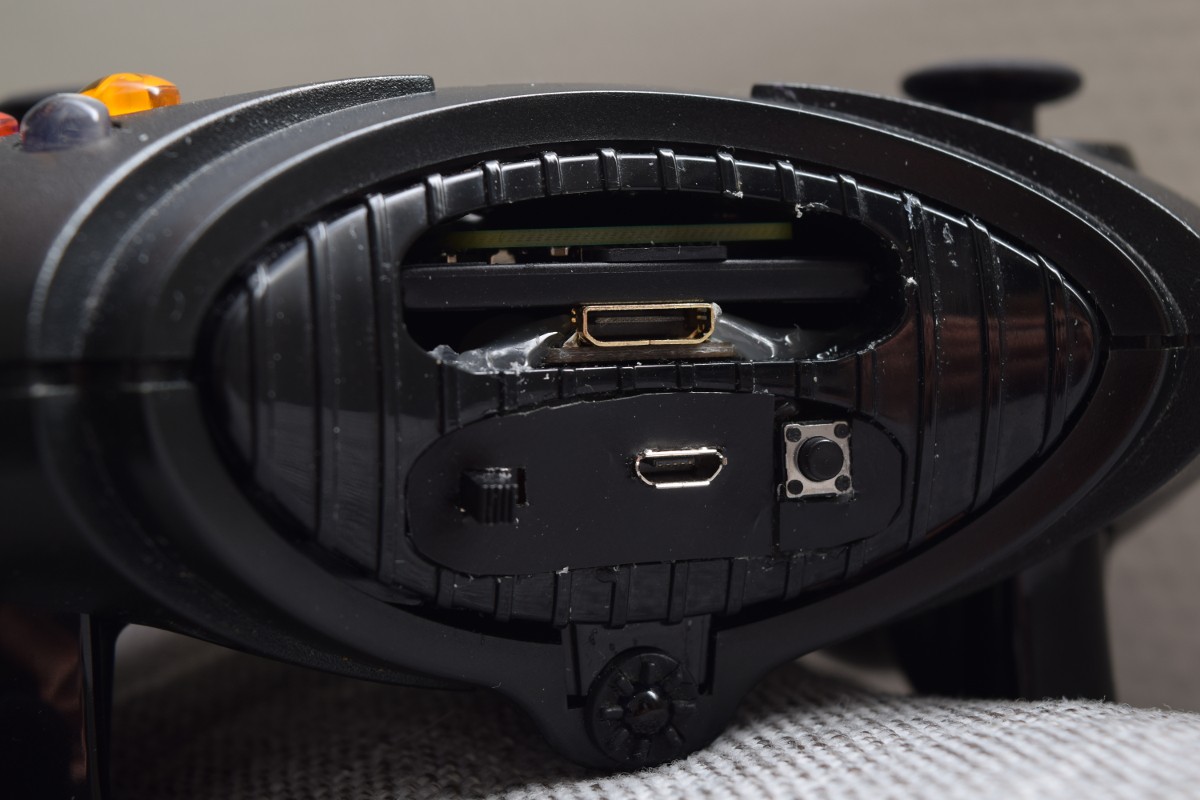
Hot glue, the fantastic material for when not having access to 3D printers. The left slider switch will be implemented as a toggle between gamepad mode and IR remote mode, the USB port for charging the battery (directly connected to the powerboost 1000c) and the button for booting and shutting down. The IR diode can be seen at the bottom where the cord normally would be connected to the case:
The following was the first assembly with all components ready, this design was however changed further on due to some space issues with the original pcb:
I also tested some assembly of the raspberry pi in the case:
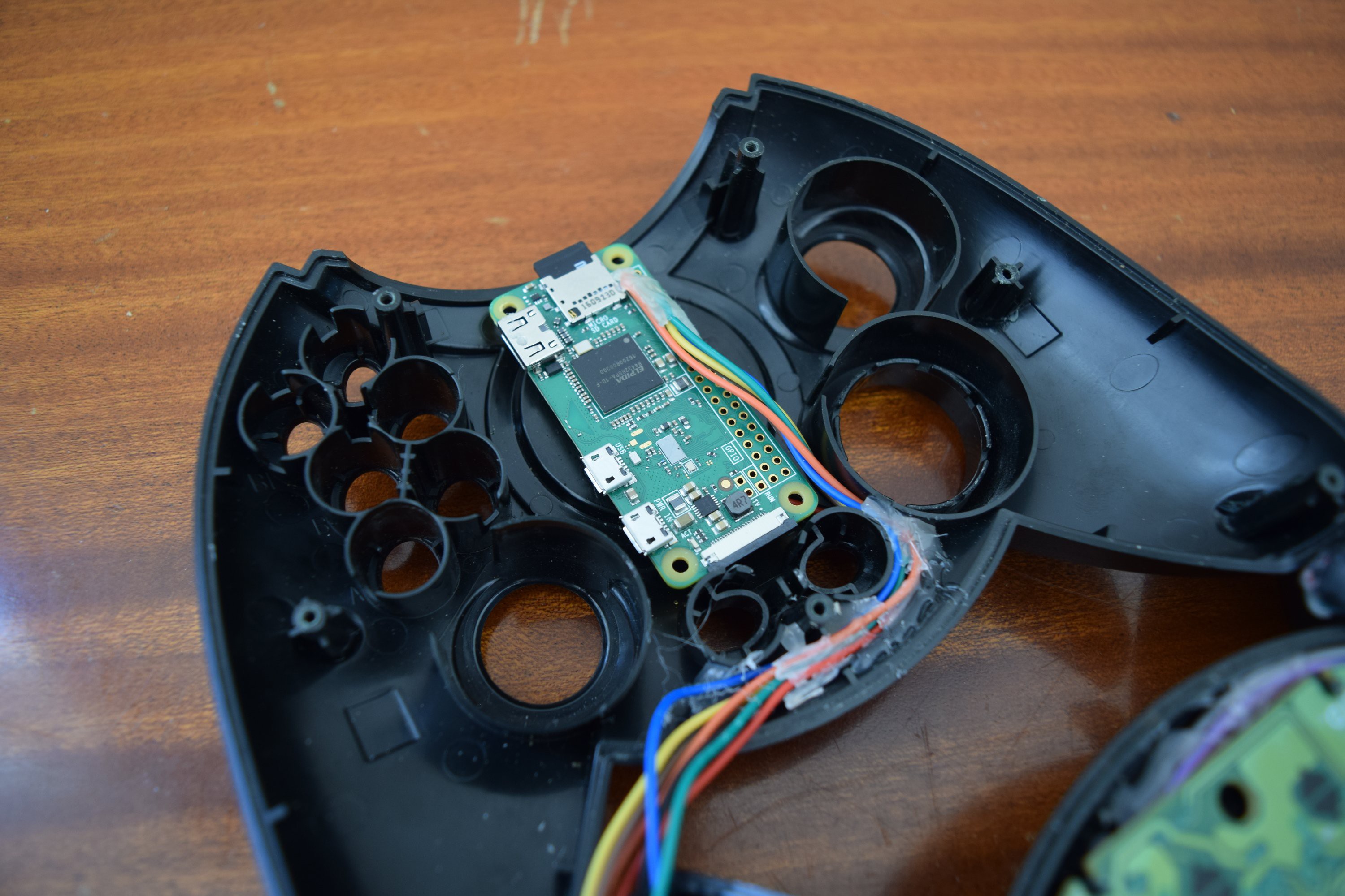
The revised design where I removed the USB port from the powerboost and made some other slight changes:
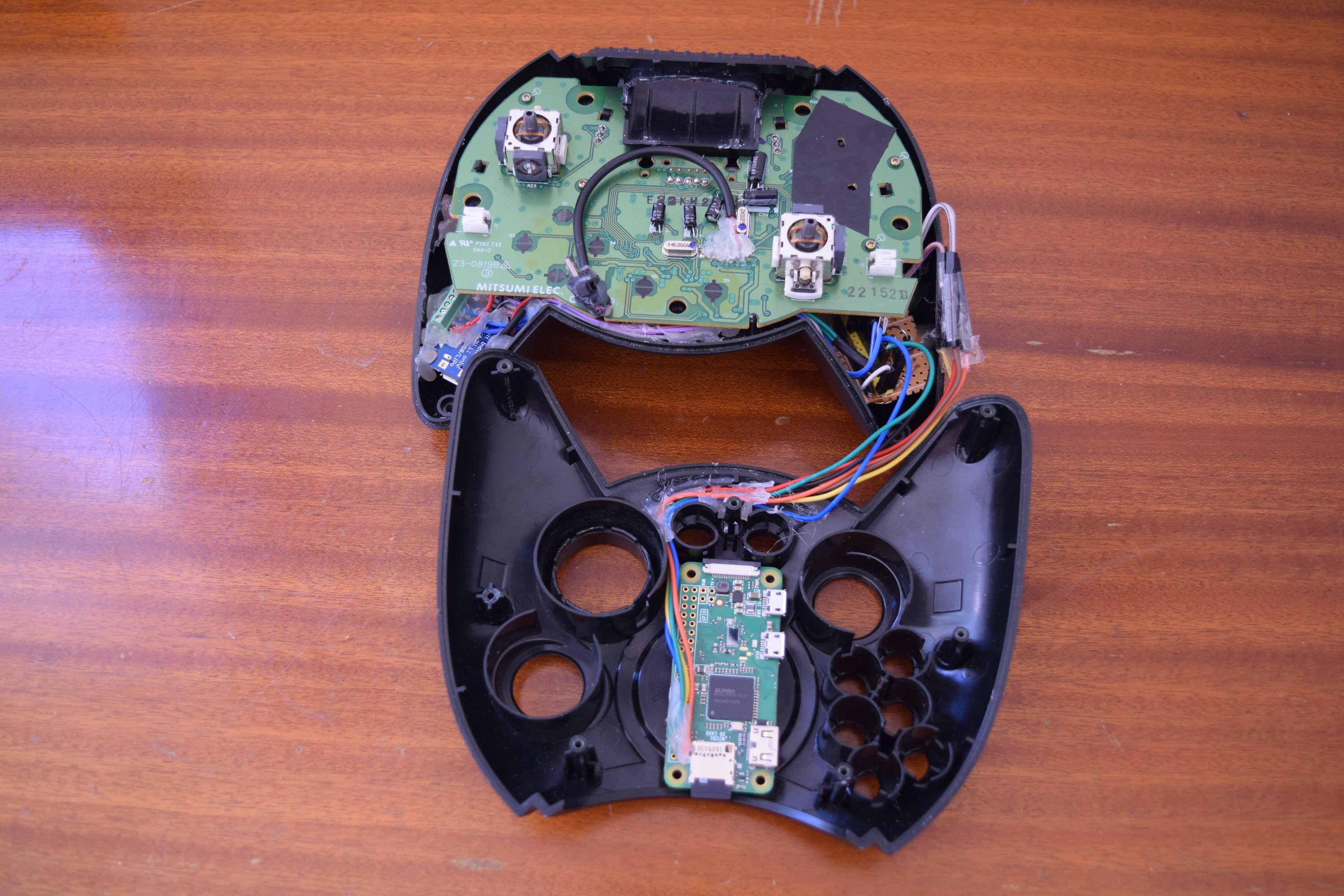
Hot glue deluxe, wouldn't want rattling inside the case:
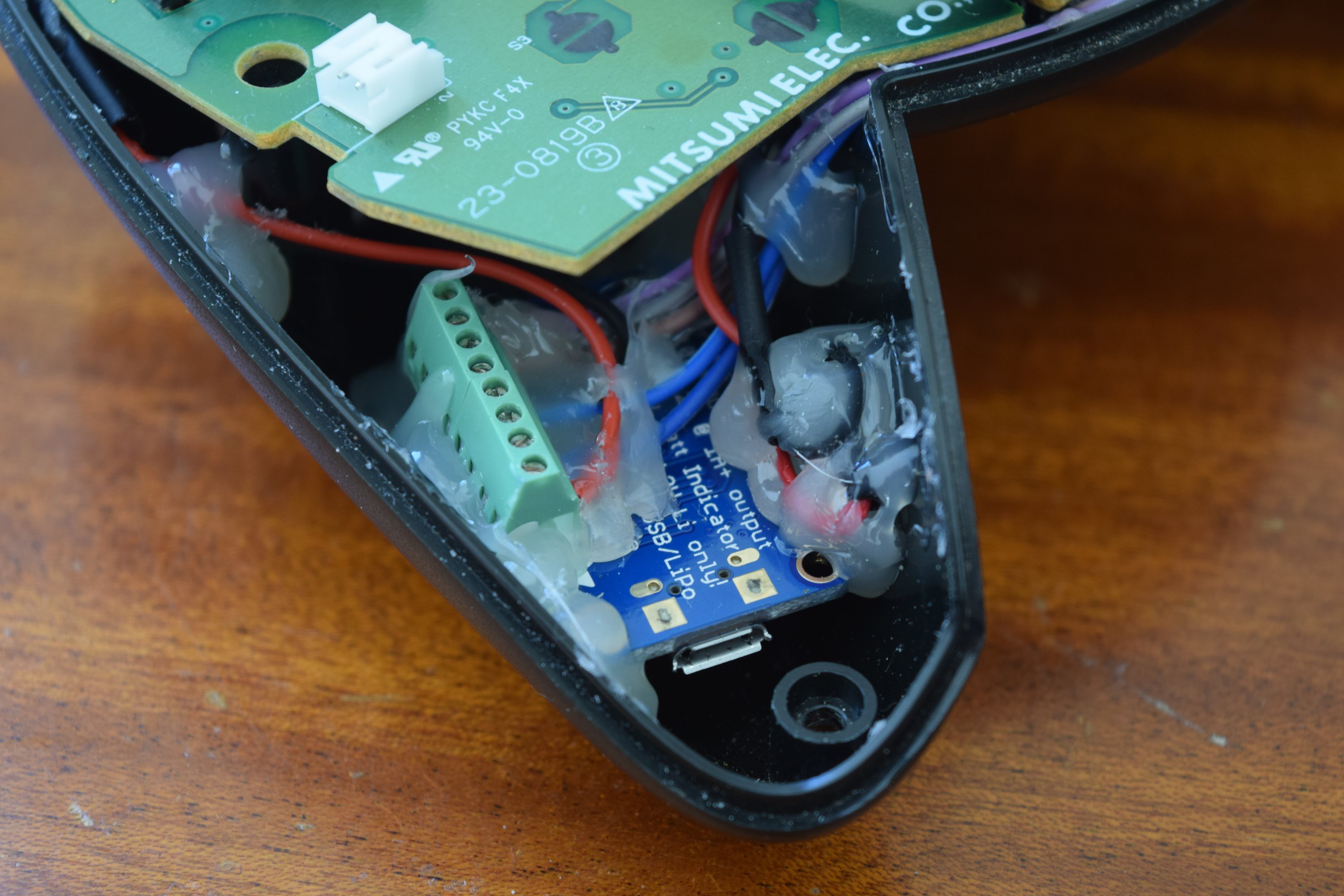
Also enforced the ports with more hot glue to handle plugging in and out the USB connector without breaking. How the raspberry pi fits when the case is together can also be seen here where the free space under the pi will be used to house the HDMI out later:
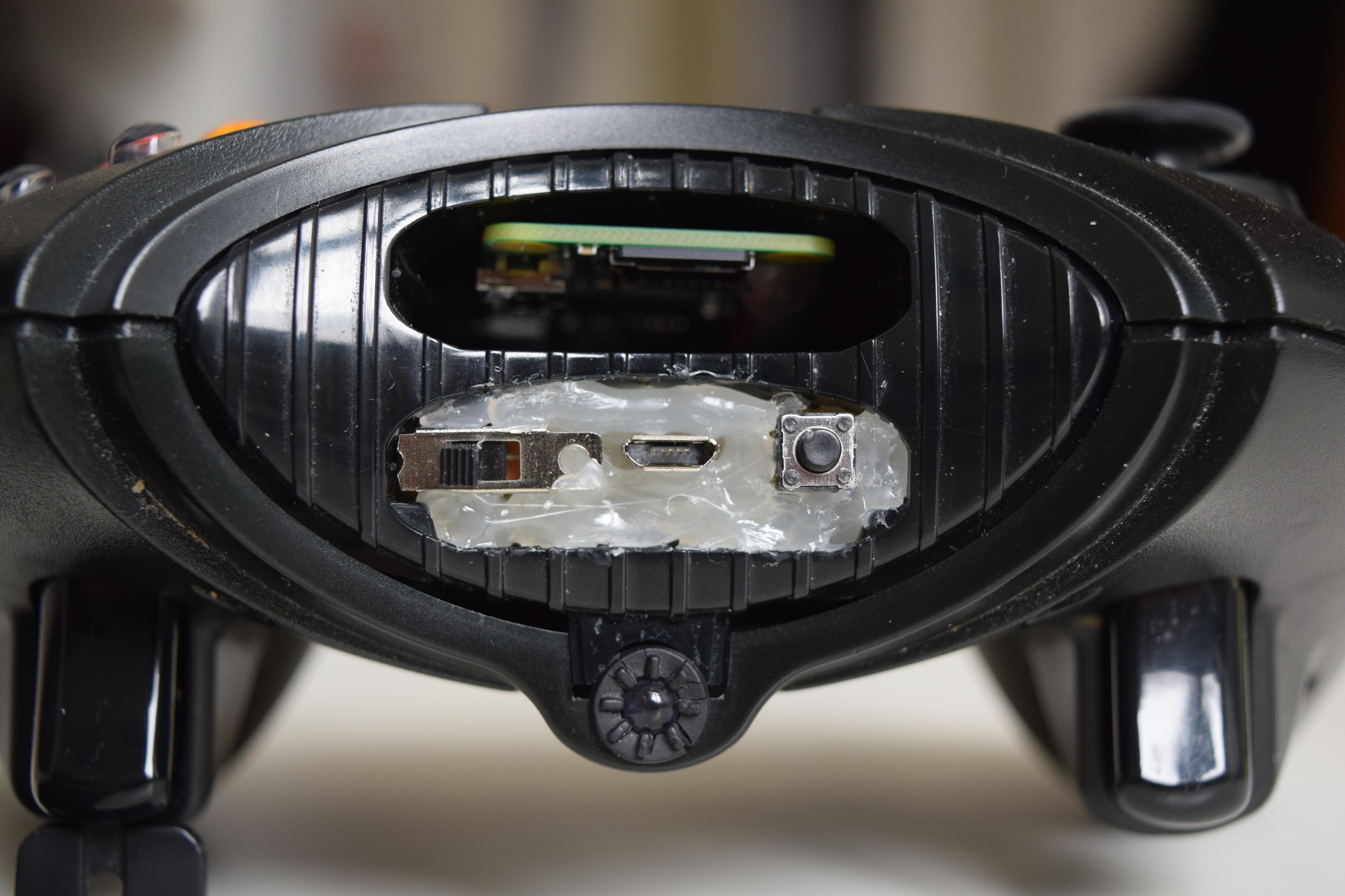
To clean up the look a bit I glued a plastic faceplate onto the hot glue to hide the monstrosity, turned out quite well:
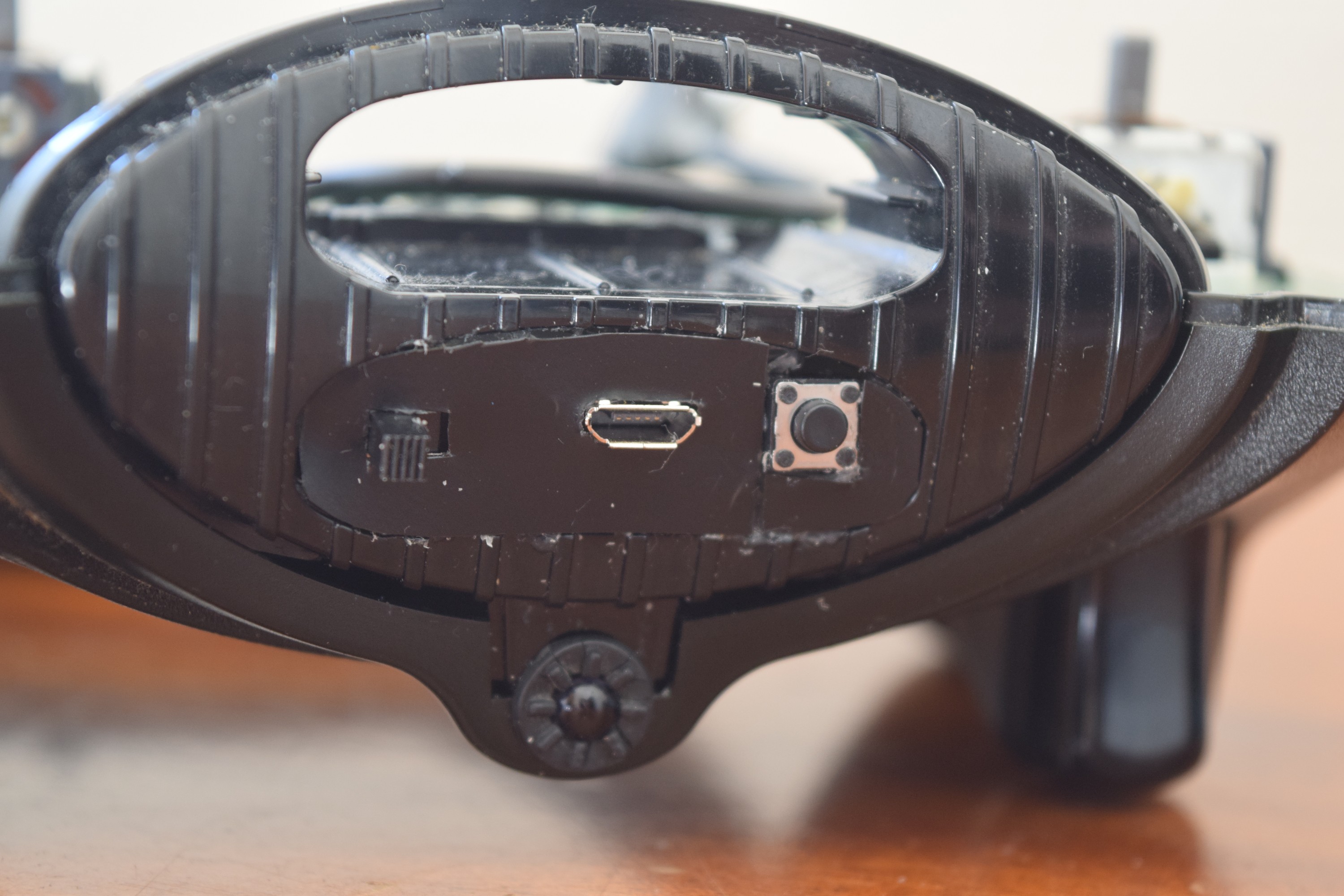
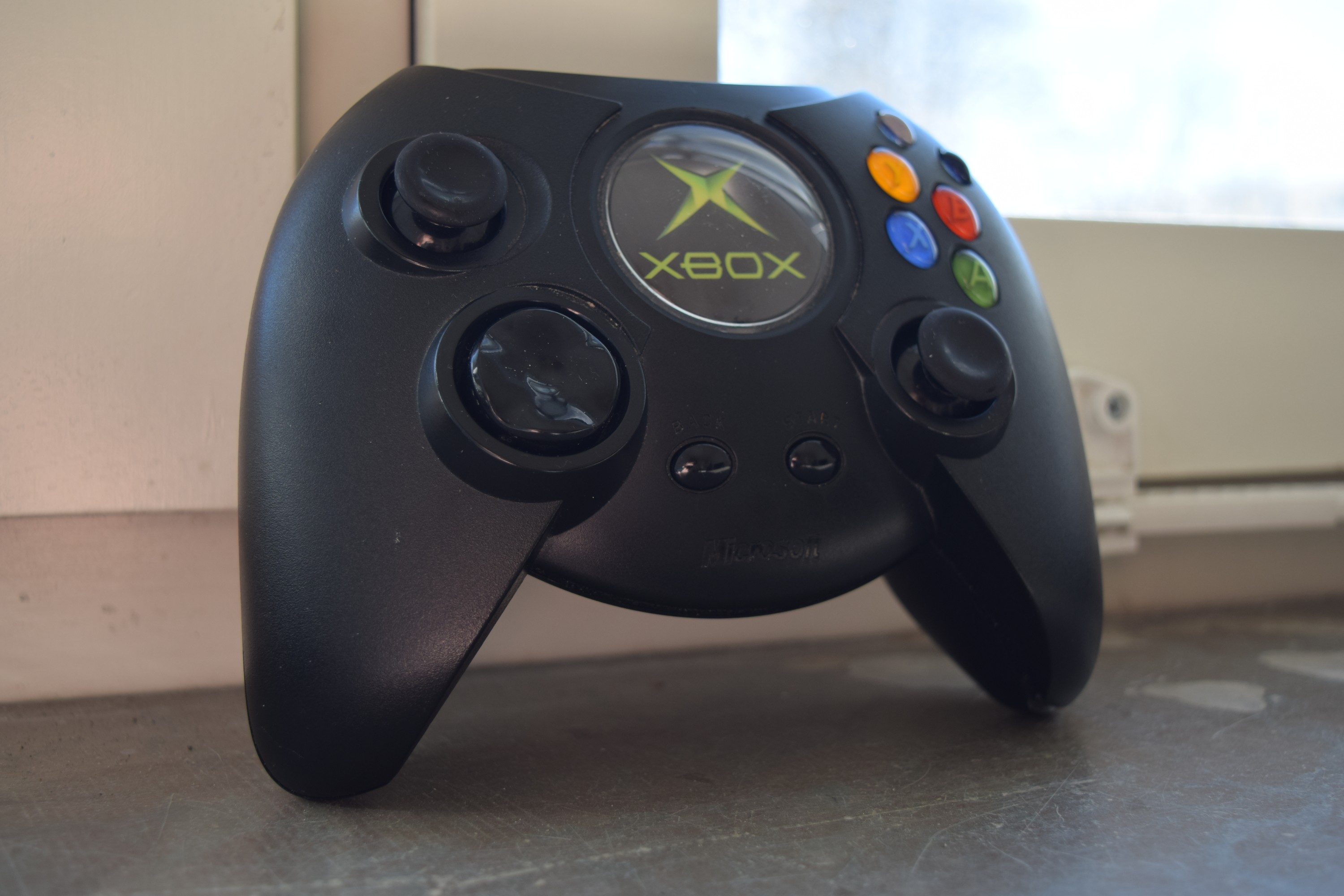
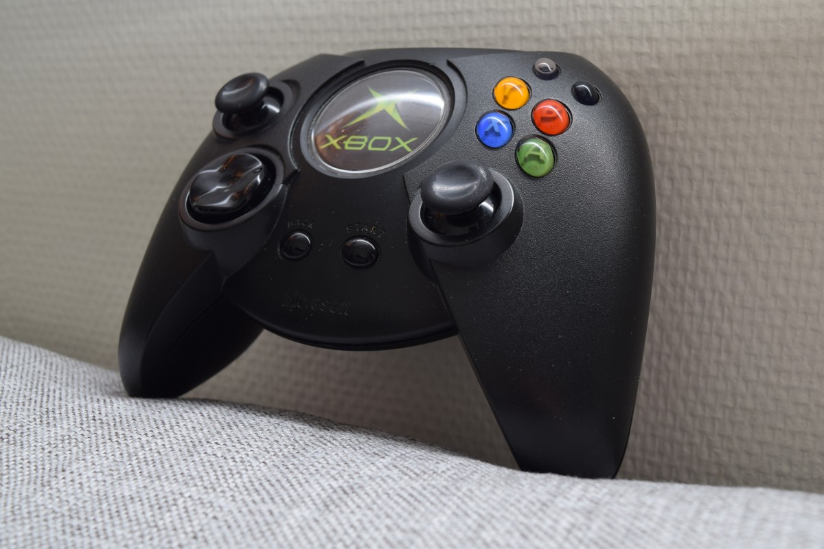
The controller is now almost ready, still waiting for the arrival of the HDMI ribbon extender that will be used for output:

 Michael Mayer
 Taylor Hay
 kenttrammell