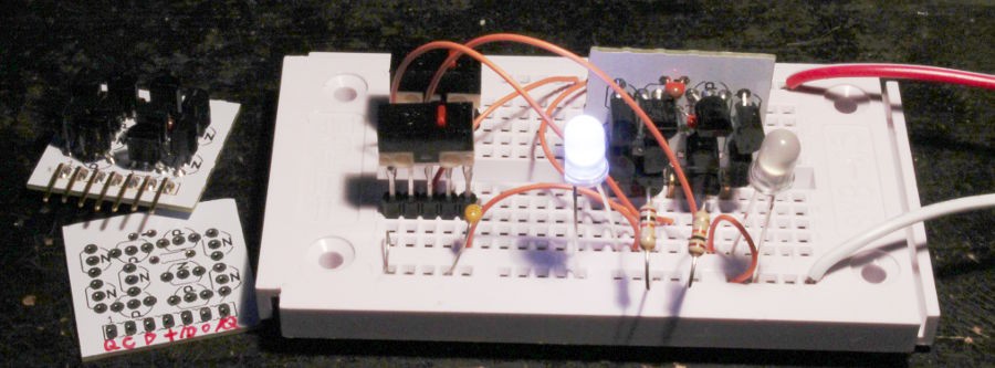
After soldering, the next step is to test the proper operation of the 10TFF module. I used a small breadboard, which is unusual, but I'll solder a board with performated FR4 soon, since I'll have to test tens of modules !
(this is the moment when you realise that some markings are welcome on the board to indicate the function of each pin).
Two white LEDs are connected directly to the Q and /Q outputs.
I use one SPDT push-button to steer Vcc (3V) from one data input to the other. Pull-down resistors do the rest.
The clock input uses another SPDT switch (selecting from 0V and +3V), with a capacitor for debouncing.
And the two modules are tested "good" on their first pass !
 Yann Guidon / YGDES
Discussions
Become a Hackaday.io Member
Create an account to leave a comment. Already have an account? Log In.