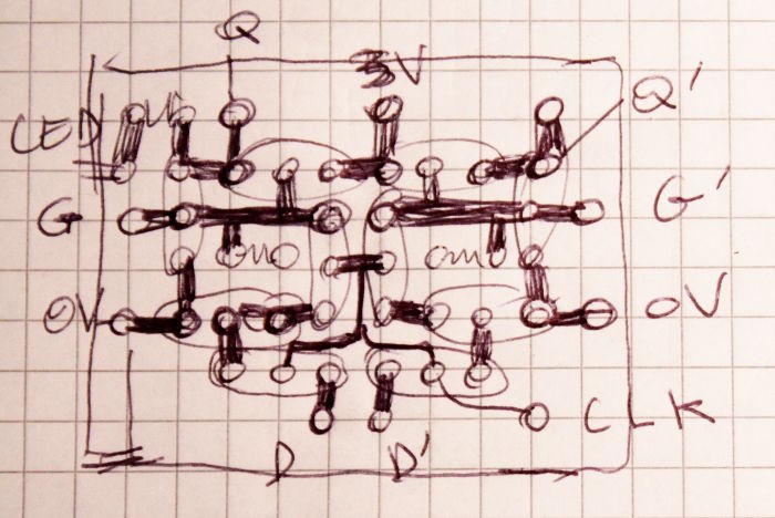
A bit of sketching leads me to the following layout:
The upper-left corner has a resistor to connect to a LED to show the predivider's activity. When connected to Q' through 2 parallel, reversed LEDs, it can show two states of a Johnson counter.
At first, I thought about making 2 modules with 5T each because the FF cell is symmetrical. It would be more modular and easier to test and repair.
I was convinced by the space savings so I worked on one half and mirored it. The module can still be handled individually and several are then wired to make dividers or Johnson counters.
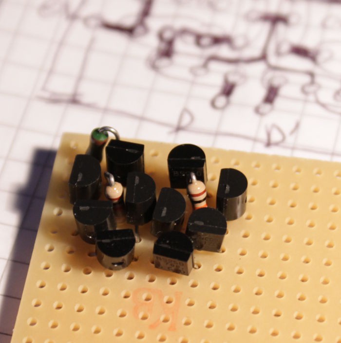
Some soldering later and there it is : my first module :-)
It looks like a crowd surrounding 2 somethings :-D
It would also make a nice "Square inch" PCB for beginners. It's pretty compact and will take even less space with SMD parts but for now I want to play with the through-hole version... I haven't tested it yet and now I must develop a verification procedure.
After I've made several modules, I'll build a small predivider and one 5-stages Johnson counter :-) Then, I'll make a PCB layout with Eagle.
Edit: PCB layout: done
 Yann Guidon / YGDES

Discussions
Become a Hackaday.io Member
Create an account to leave a comment. Already have an account? Log In.
When doing "pre-layouted" design on donut-pcb's like this is usually let some parts share holes whenever possible. For parts with thin leads like 1n4148, 1/6w resistors and such it's easy to have three leads in the same hole.
This makes the layout much denser and also saves a lot on soldering time. The drawback is that the design must be debugged in advance since it's almost impossible to change a part when sharing a hole.
Are you sure? yes | no
Yup but it's mostly transistors here and their bodies take some room.
I could have soldered the pins in a triangle instead of in a line but it didn't fit with the topology. Furthermore, I'm not trying to get extra-small either. I need some headroom to poke and peek...
Are you sure? yes | no