In Debouncing The Smart Way, I assumed that what I heard was true.
In practice... it's different.
So I made the circuit and I admit "it works as is". Of course I tried to tweak it and it didn't work.
Debouncing is quite OK so yes, it's OK for a power supply control or a mode/control/status button (most likely).
My disappointment comes from the fact that when the button is kept pressed, no oscillation appears. In fact it remains pretty stable... And it is not easy to make an edge detector, it adds too many parts.
Back to the start. Some more googling takes me to Bowden's page http://www.bowdenshobbycircuits.info/page9.htm and the following circuit strikes me as ... obvious. And it works both for bipolar transistors (even Ge PNP) and MOSFETs.
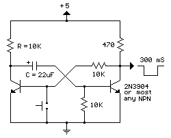
The MOSFET version also draws less power (no current when idle) and allows some kind of "autorepeat", thanks to an additional RC cell. Autorepeat can appear with a different timing, independent of the debounce circuit.
Let's just do it !
After several attempts, it appears that the MOSFET version has a problem since the output is not correctly debounced. The reason is that the push-button is directly connected to the output and that provides a path for the glitches that I still can see on the oscilloscope.
But we're almost there ! The question is just : where to put the push-button ?
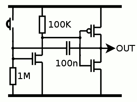
The following circuit gave a very good result, even with a noisy switch :
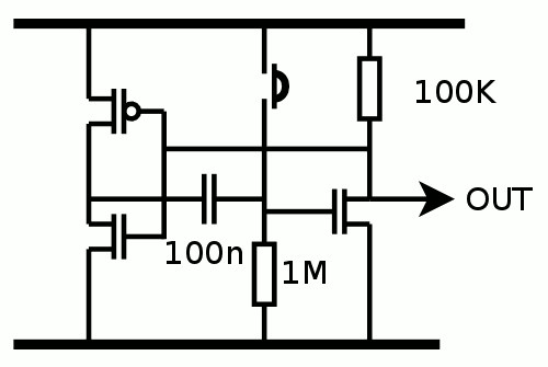 The inverter gate on the left provides some positive feedback through the capacitor, providing sharp edges at the output (the rising edge is a ramp until Vcc/2 then a very steep front). This circuit is easy to miror to provide a positive pulse and it draws no current when inactive, which is another desirable characteristic :-)
Tomorrow I'll try the PNP/Ge version.
Whyyy am I so dumb ? The proper output should be on the other side :
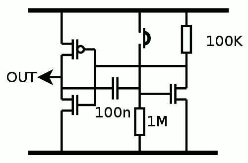
and the output signal is perfect. To make the circuit even more perfect, Alexander wanted it to be flipped :-)
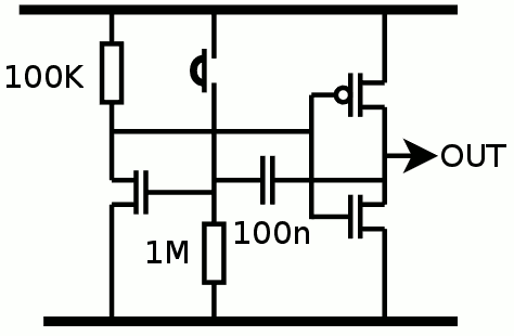
And since he's a perfectionist, here is his version:
(let's have a poll, which is better ? :-D)
I keep it simple and give up the "autorepeat" feature. This simple circuit will be added to every Johnson counter, along with a reset circuit, so there is no need to press the button 3600 times :-)
 Yann Guidon / YGDES
Discussions
Become a Hackaday.io Member
Create an account to leave a comment. Already have an account? Log In.