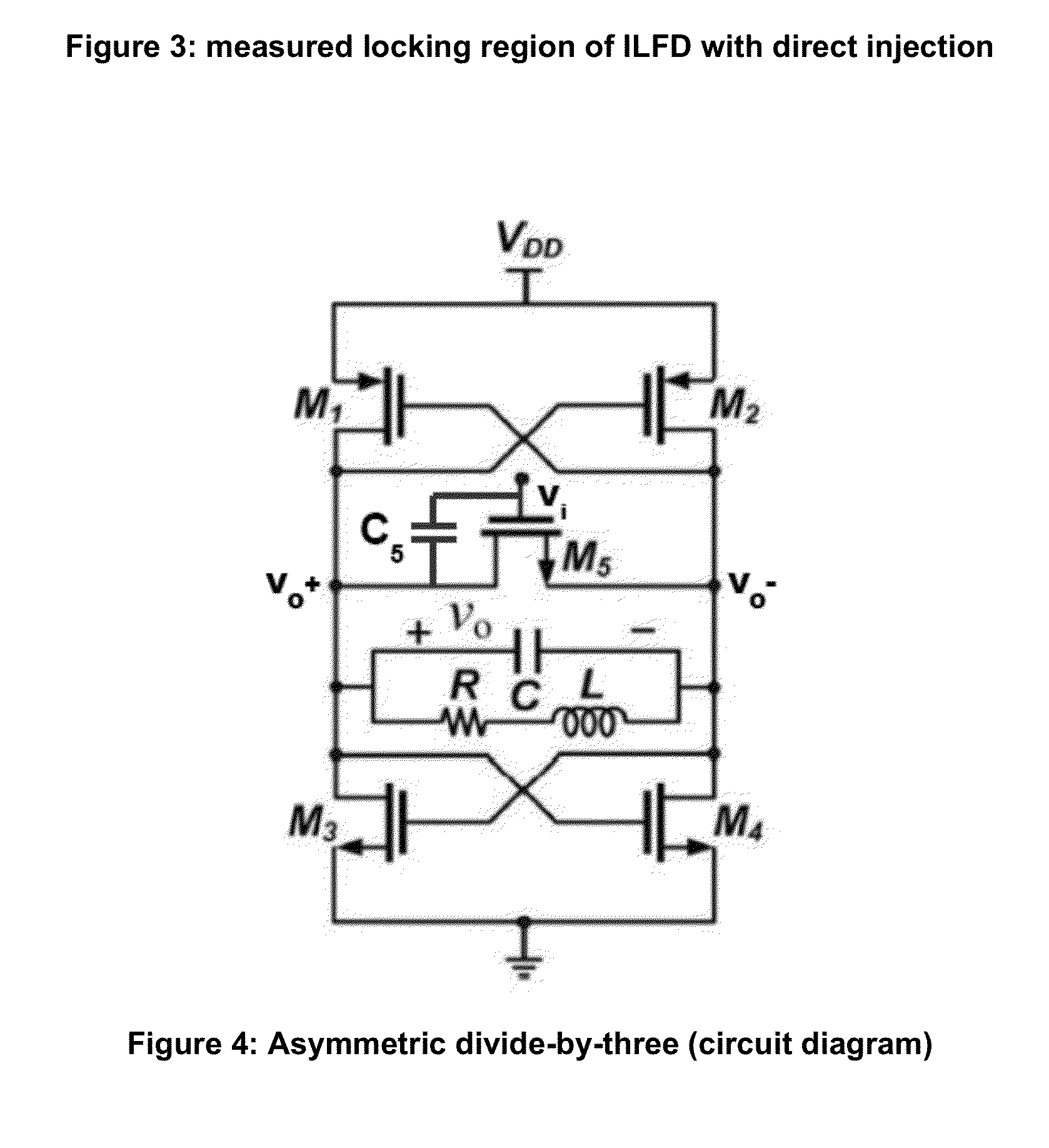
While researching a different subject (divide-by-N without flip-flops), I found the following drawing :

This circuit is actually a high frequency tuned oscillator that gets synchronised to an incoming signal. Now, forget the MOSFET M5 and look at the RLC network in the middle. Doesn't this look like the equivalent circuit of a quartz crystal ? And the MOSFET are actually cross-coupled inverters and there is no coupling capacitor (but one feedback resistor)... Is this the ideal circuit ?
mind: blown
More informations about Injection-Locked Frequency Dividers at http://www.ece.rochester.edu/projects/laics/ilfd.html
Of course I have to test it.
My first test : the circuit oscillates. At 5V. At about 7MHz. The crystal has no effect and the shunt/feedback resistor must be very low. And there is a lot of 3rd harmonics, depending on the voltage ...
 Yann Guidon / YGDES
Discussions
Become a Hackaday.io Member
Create an account to leave a comment. Already have an account? Log In.