-
The most simplest is the most easiest
12/16/2016 at 00:22 • 0 commentsSucces! Of sorts:
This video demonstrates the effect that I was hoping for: moving recognizable shapes with incredibly low resolution (50 "pixels" in all). Notice that if you pause the video above, the still image shows nothing resembling a circle. The resolution is simply too low to represent such a shape. Yet, as soon as the "shadow" starts moving its shape is definitely circular and you might even spot that the shape is somewhat elliptical.
There is a lot more going on than meets the eye: First of all all the positions of the randomly distributed LEDs have been automatically registered of course, because that is what this project is all about. Secondly, the edges of the shadow circle need to be fuzzy. The effect is as if the LEDs are partially occluded when the edge of the circle moves over them. If this isn't done, then the movement is a lot more pixelated and the shape isn't recognizable anymore. Thirdly: this works a lot better for a dark circle on a light background than the other way around. Apparently, the human brain is better at discerning shapes if they occlude light sources than they are at identifying shapes "made of light". Finally, there's a minimum speed at which the object can move and still have a recognizable shape. If it moves too slow, its not recognizable as a circle anymore.
All of this is teaching me a lot about the human visual system.
In order to get the result above, the original plan had to be changed in two ways:
- Although the LEDs are in a random pattern, they weren't "draped". Instead I just drilled holes in a plywood board. This makes recognizing the LEDs an awful lot easier since now they're nicely spaced and there are no strange reflections
- In the quest for working OpenCV registration of LED positions I'd already switched to a much simpler pattern, where the LED just light one-by-one. This had mixed results with the draped LEDs, but it worked from the start with the nicely spaced and separated LEDs-onna-board.
This is the pattern that was used to register LED positions:
The code that creates this pattern using a plain AVR is in the function simple_registration(). This pattern is then analyzed using the code in LedMapping.cpp. Finally, the output of LedMapping.cpp is used to hard-code the LED positions in a demonstration program.
The board as it is now will be placed under the awning of the front door, for Christmas only and I'm not so much interested in creating floating ghost shadows there (hmm. definitely an option for Halloween). I think I'll stick with the simple location-independent random starry sky pattern for the holidays:
Given that there is quite some hardware work to do (painting, getting the 5V power to the board outside) limiting the scope at this point should increase the chances of the project actually being finished before Christmas...
-
Nelder-Mead in the desert
05/29/2016 at 15:57 • 0 commentsOK. Just so you know, this project isn't dead. It's just moving in its own pace, that's all...
There are some problems though. As I wrote in a previous log, the OpenCV algorithm used to detect the LEDs in an image has many parameters, and no set of parameters seemed right in all circumstances. A logical next step was to try an optimization algorithm such as Nelder-Mead to find the right arguments.
Nelder-Mead is a relatively simple method to find the maximum (or minimum) value of a function. It does not require the derivative of the function, which makes it applicable in a large number of cases. In essence, for a function that takes two inputs, applying Nelder-Mead consists of walking a triangle downslope across the solution landscape. The triangle may grow or shrink and it uses some tricks to jump out of local puddles. For more than 2 parameters, the triangle becomes a simplex, a figure that can be described by n+1 points in an n-dimensional space.
![Nelder Mead over Banana function. Image by wikipedia editor Simiprof.]()
Any optimization needs a cost function with n inputs and one output, the cost. For a cost function, I chose the absolute difference between the actual number of LEDs and the detected number. I experimented with different inputs, zooming in on the following three parameters:
- minimum distance between detected LEDs
- minimun size of detected LEDs (area of detected feature)
- maximum size of detected LED
I just needed to tweak the algorithm to only search in positive values, which is easy just square the proposed inputs before using them in opencv, and then: Let it rip!
Not.
With the settings as chosen above, the NM algorithm could not find any combination of parameters that detected any LEDs, it would just quickly shrink the "triangle" on a set of parameters that resulted in zero LEDs found.
The problem was that the parameter space consists largely of big areas where the algorithm can't find any LEDs at all. If all the points on the NM simplex have the same cost (in this case the maximum cost of finding zero LEDs), the algorithm will just shrink the simplex until it is so small that the algorithm concludes that there is no better solution to be found. So we have a large "flat" desert area where nothing is found, with a small valley somewhere, but the simplex just never walks close to the valley.
There are several ways around this. The first way is to first go hunting for the valley. This can be done for instance by sampling random points in the parameter space, or a grid of points, until a point is found with a lower cost than the other points. As soon as we have a simplex with at least 1 lower point, it will start to walk into that valley.
A second option is to artificially create random hills in the "flat" part of the space. This can be done by adding a random value to the cost when the cost is at its maximum. As a result, the simplex will go wandering around in the parameter space and it might just stumble upon the real valley. This is the option that I chose first, because it was easy to implement. This actually works, if the NM algorithm gets enough time (iterations) to walk around, but it means that my desktop PC needs in the order of seconds to find a suitable parameter set, which is long, considering I want the final algorithm to run on a phone.
A third option is to find an initial set of parameters which may be close to a best solution in most cases and use those as a starting point for NM. This requires some experimenting and tweaking and that is where I'm currently at.
-
First OpenCV experiments
01/31/2016 at 15:33 • 0 commentsNow that the LEDs are blinking, it's time to start working on the recognition software (ongoing experiments on GitHub). The plan is to use OpenCV, and more specifically OpenCVs SimpleBlobDetector to recognize the LEDs.
![]()
Feature detection with SimpleBlobDetector is fairly easy:
Mat cooked = ...;
SimpleBlobDetector::Params params;
params.minDistBetweenBlobs = minDistance;
params.filterByInertia = false;
params.filterByConvexity = false;
params.filterByColor = false;
params.filterByCircularity = false;
params.filterByArea = true;
params.minArea = minArea;
params.maxArea = maxArea;

Ptr<SimpleBlobDetector> detector = SimpleBlobDetector::create(params);
vector<KeyPoint> features;
detector->detect(cooked, features);
The idea was to filter the blue (or red) parts of the image and then running the blob detector to find the blue (or red) spots.But not everything is as simple as it seems: using default parameters to the blob detector resulted in finding zero LEDs. Luckily, OpenCV allows you to quickly create some sliders in a UI that allowed me to tweak the parameters until a reasonable match was made, that looked like the image at the top of this log entry.
The most important parameters appear to be minimum- and maximum area size and minimum distance between blobs, but I suspect that these parameters are very much dependent on circumstances like distance to the LEDs, brightness settings of both the video and the LEDs, etc.
So at this point, there are some things to consider:
- Would it be possible to automatically find the ideal parameters, for instance by running a generic optimization algorithm? I have some previous experience with implementing Nelder-Mead as an optimization, so it shouldn't be too difficult to try this.
- The inputs that I'm giving SimpleblobDetector may not be optimal. The results above were obtained by giving the blob detector an image that consisted of the blue channel of the input image, already pre-thresholded. Determining a threshold is exactly what the SimpleBlobDetector is supposed to do by itself.
- Another improvement that I could try is to feed the blobdetector the difference between a reference image with unlit LEDs and the image with LEDs lit. This may run into movement artifacts, but it's worht a try.
- The LEDs are oversaturated in the image. It seems like a good idea to dim the brightness of the LEDs a little, maybe by some constant value, maybe by dynamically adapting the brighness if feature registration fails.
Because over-engineering is fun, my next step is going to be to try Nelder-Mead on the blob detector parameters...
-
Patterns
01/30/2016 at 16:08 • 0 commentsSome thoughts on the patterns:
- In a video, it should be easy to find the start of the pattern and the moments in time when the led patterns change.
- Also, since there might be some slight movement in the video, the sequence should be as short as possible
- For the same reason, it would be nice if LEDS are on as much as possible in order to track them across frames.
Below, you can see version 1 (well, version 3 actually) of the pattern. It's a simple binary sequence where 0 is encoded as red and 1 is encoded as blue (or the other way around, doesn't really matter)
Using two colors at the same time (vs just switching half of the LEDs on at each step) should help a lot in disambiguation, where two LEDs are so close together that they are registered as one.
I'm still not sure whether this is over-engineered. Maybe just switching the LEDs on one-by-one would be enough and surely this would also solve ambiguity. Of course this would take a lot longer. Currently I'm aiming at 2 video frames per step in the sequence (about 12 steps per second). The one-by-one approach would take 8 seconds for 100 LEDs, or 3 seconds if red, green and blue are used at the same time.
Another thought: to improve tracking, instead of switching off the leds in between, I could use the third color (green) in between the red/blue patterns. But all of that is better explored when implementing the actual tracking. First I need to detect the LEDs in the video to start with. More about that in the next log...
-
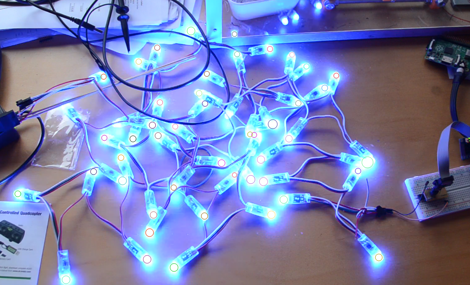
The LEDs are in
01/30/2016 at 15:22 • 4 commentsNo LED identification without LEDs, so the first step in this project has been to order an LED string. After a ~20 day wait (shipping to Europe seems to take the longest), they arrived. Time to start coding.
First: let's see if my ws28811 driver still works for these strings...
Aaaand: no. Weird colors. But wait a minute, when I send pure red, green or blue, it quickly becomes clear that these strings don't accept their RGB values in G, R, B order as I'm used to with WS2811s, but in R, G, B order instead. So that's an easy fix and before the evening is over, we've got lights:
Where's my Christmas Light?
Quickly identifying individual LEDs in a randomly distributed arrangement