 Gary
Gary-
11Step 11
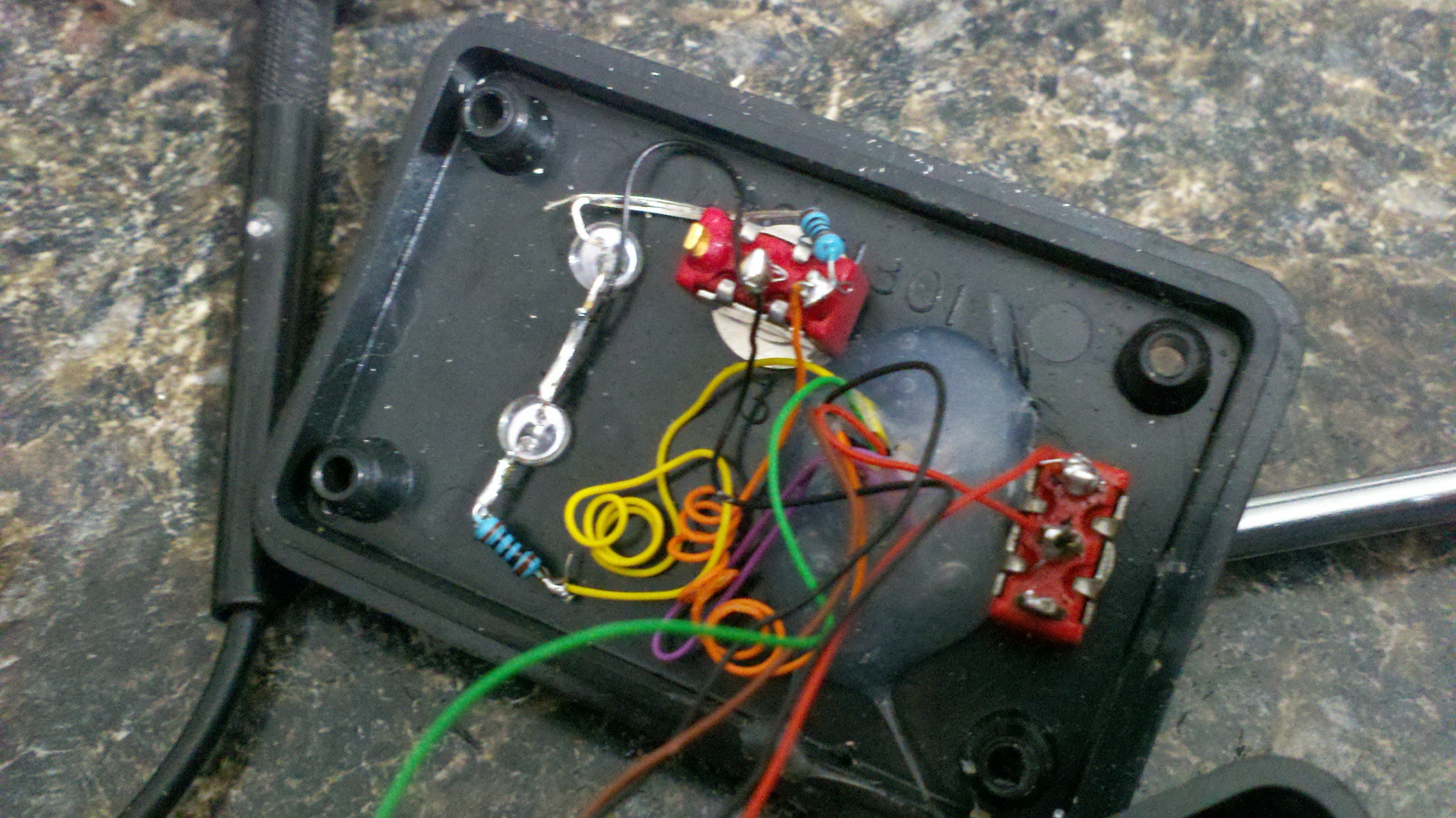
Here you can see the LED's, Power switch (left) and the program switch (center) wiring.
![]()
-
12Step 12
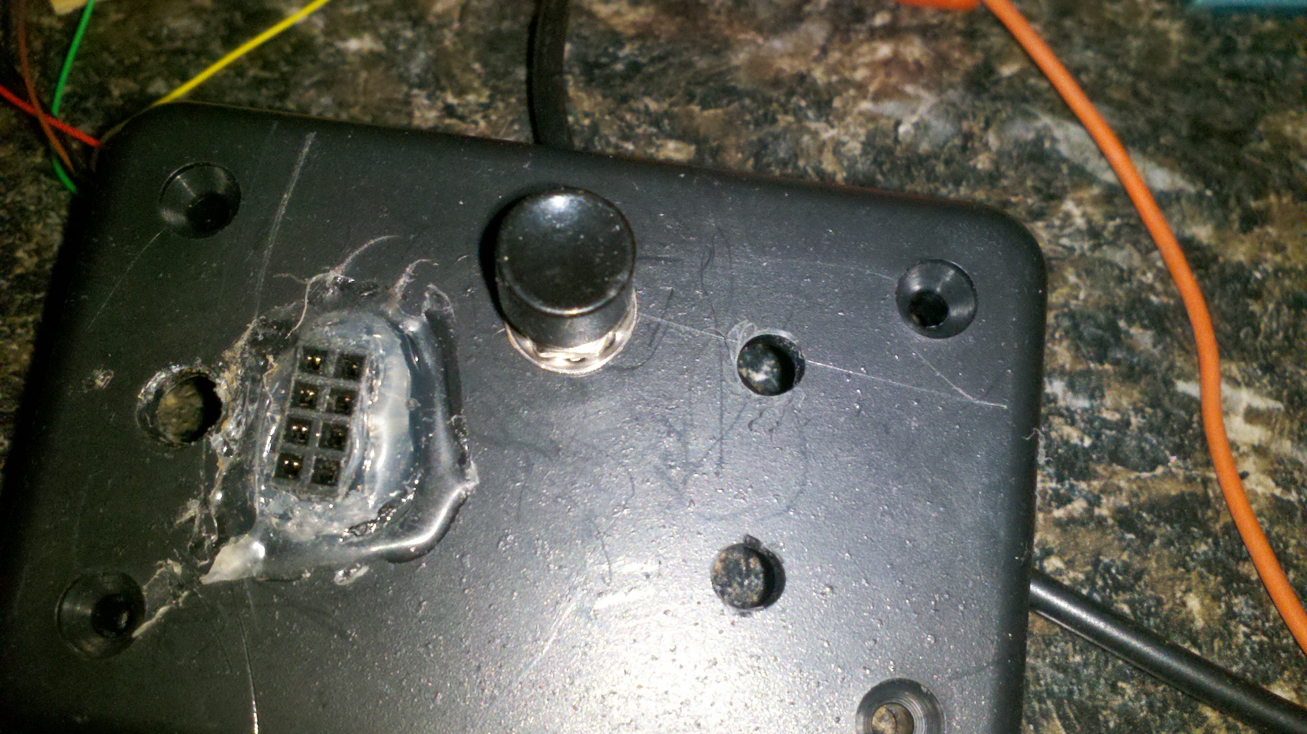
Picutre of the top of the case with holes for the pwd and power switch. Program switch has been mounted.
![]()
-
13Step 13
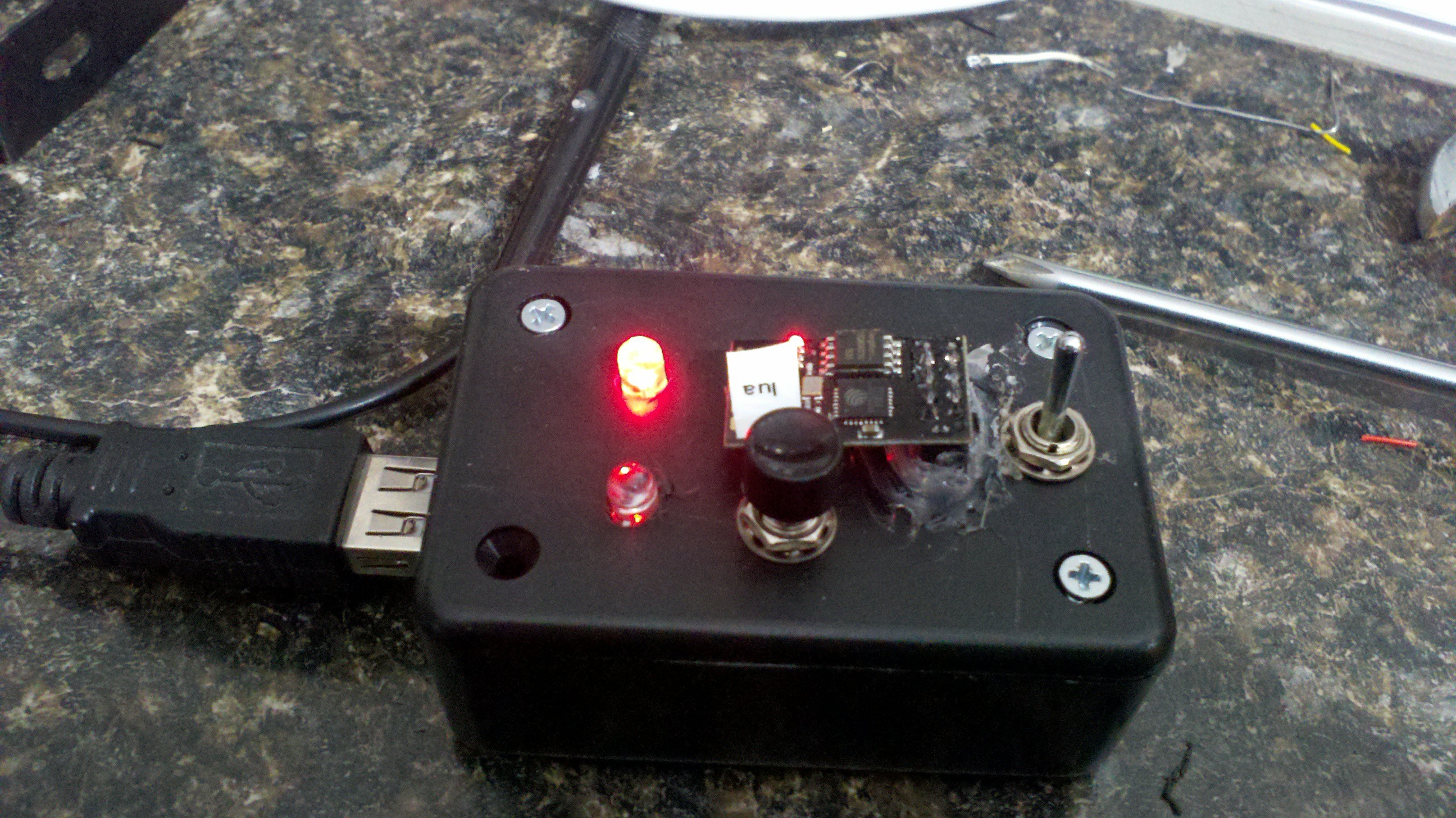
Here is the completed program with the top on the case running a simple blink program running so I can check the GPIO leds.
![]()
-
14Step 14
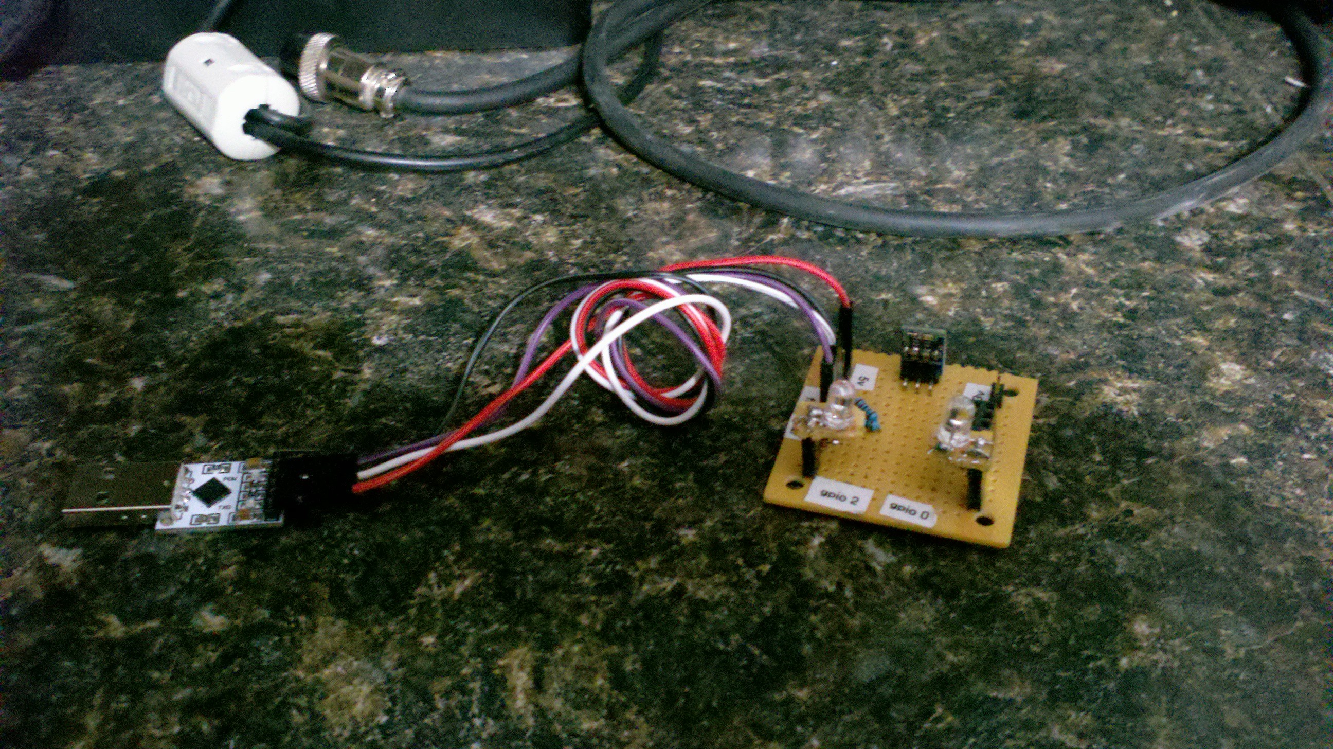
Here is another version of my programmer without a case. This is a bare board vesion following the same general schematics.
![]()
ESP8266-01 Development board
A quick and easy dev board for the esp8266-01 board
Discussions
Become a Hackaday.io Member
Create an account to leave a comment. Already have an account? Log In.