 Gary
Gary-
1Step 1
I have built several of these development boards. The contstruction technique and enclosure is up to you. there are no critical parts or tolerances. Most of my electronic parts came from various ebay suppliers.
I used wirewrap wire but any small guage hookup wire will work.
The case was one of many I purchased when Radio Shack was closing stores. You can build these on a bare board or put it in some enclosure.
The switches I have had for years and were pulls from various projects.
-
2Step 2
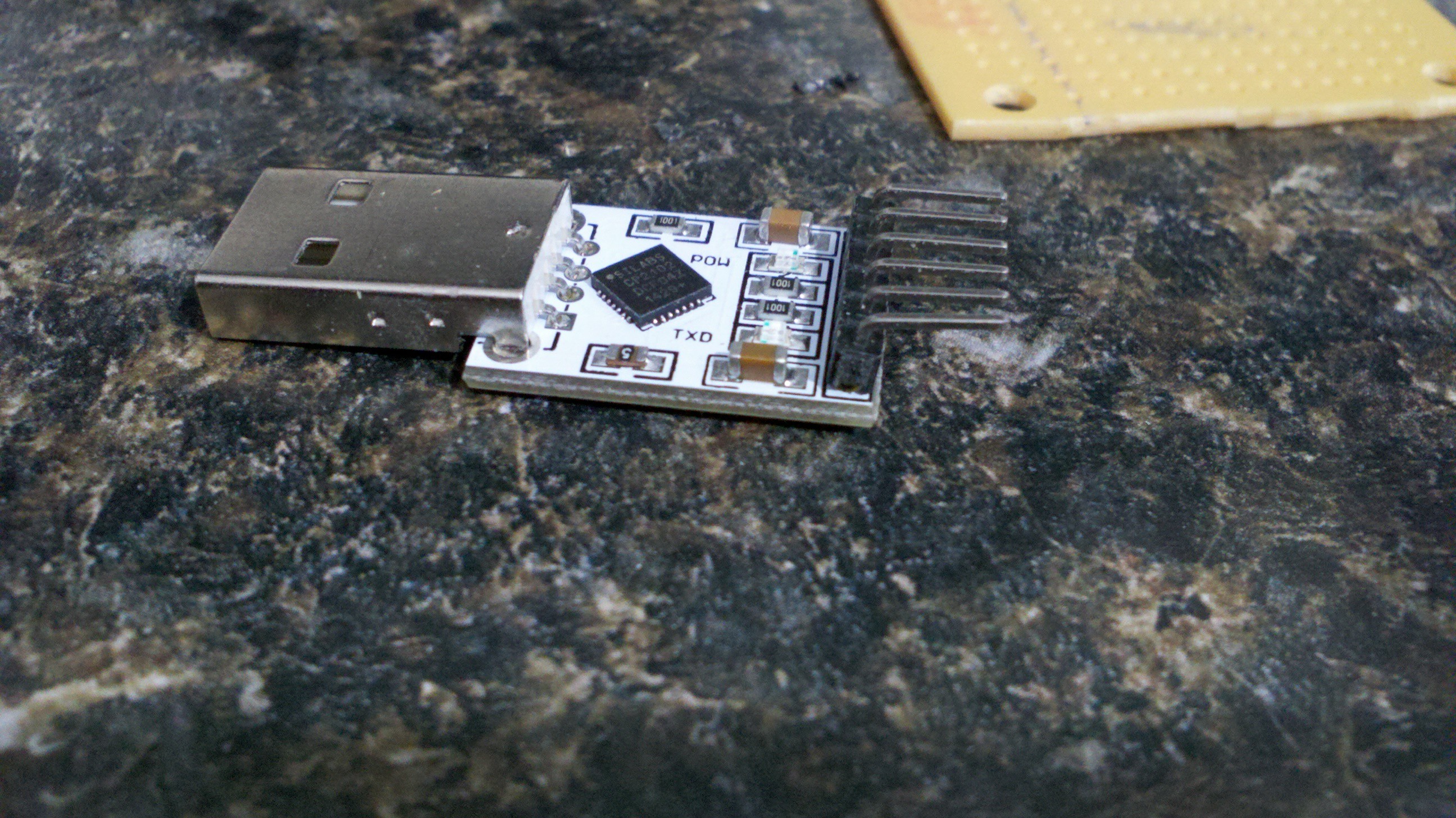
I used a USB FTDI serial port board. Plugs into a stadard USB port and provides recevie and transmit data pins along with power and ground. This specific model also provided 3.3v but didnt have the current capacity to power the esp8266, so I used the 5v line and an external regulator to get the 3.3v.
You can get similar units with mini or micro usb ports. Use the configuration that meets your needs.
![]()
-
3Step 3
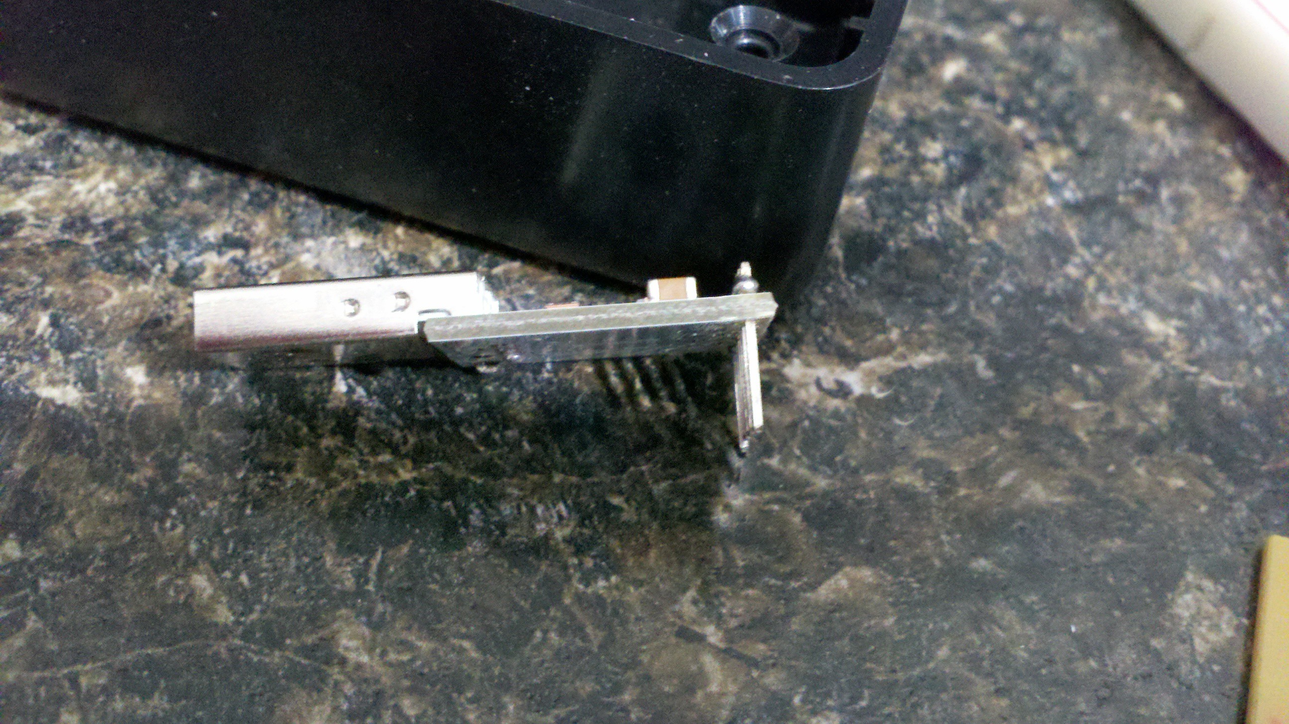
For my project I replaced the 90 deg headers on the ftdi board with staight headers so they could plug into the bread board.
![]()
-
4Step 4
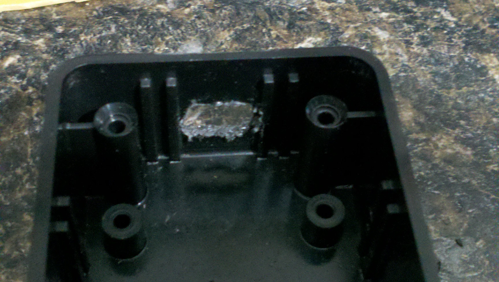
I cut a small slot in the side of the enclosure to allow the USB port on the FTDI board to sick out.
![]()
-
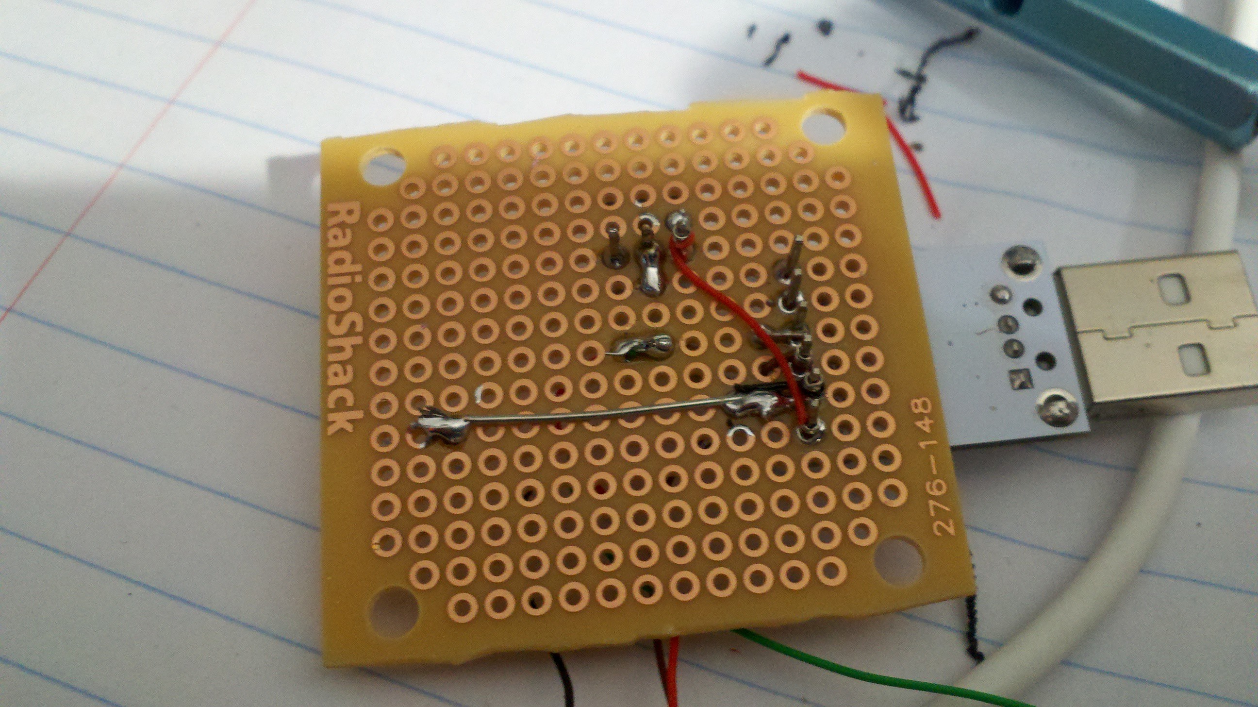
5Step 5
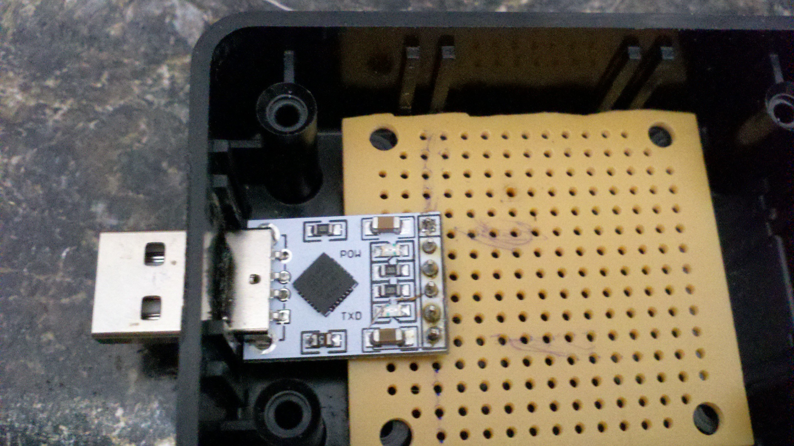
I attched the FTDI board to a small proto board and test fit the board and the proto board in the box. Once completed the protoboard will be screwed down and will hold the USB port ridged in the enclosure.
![]()
-
6Step 6
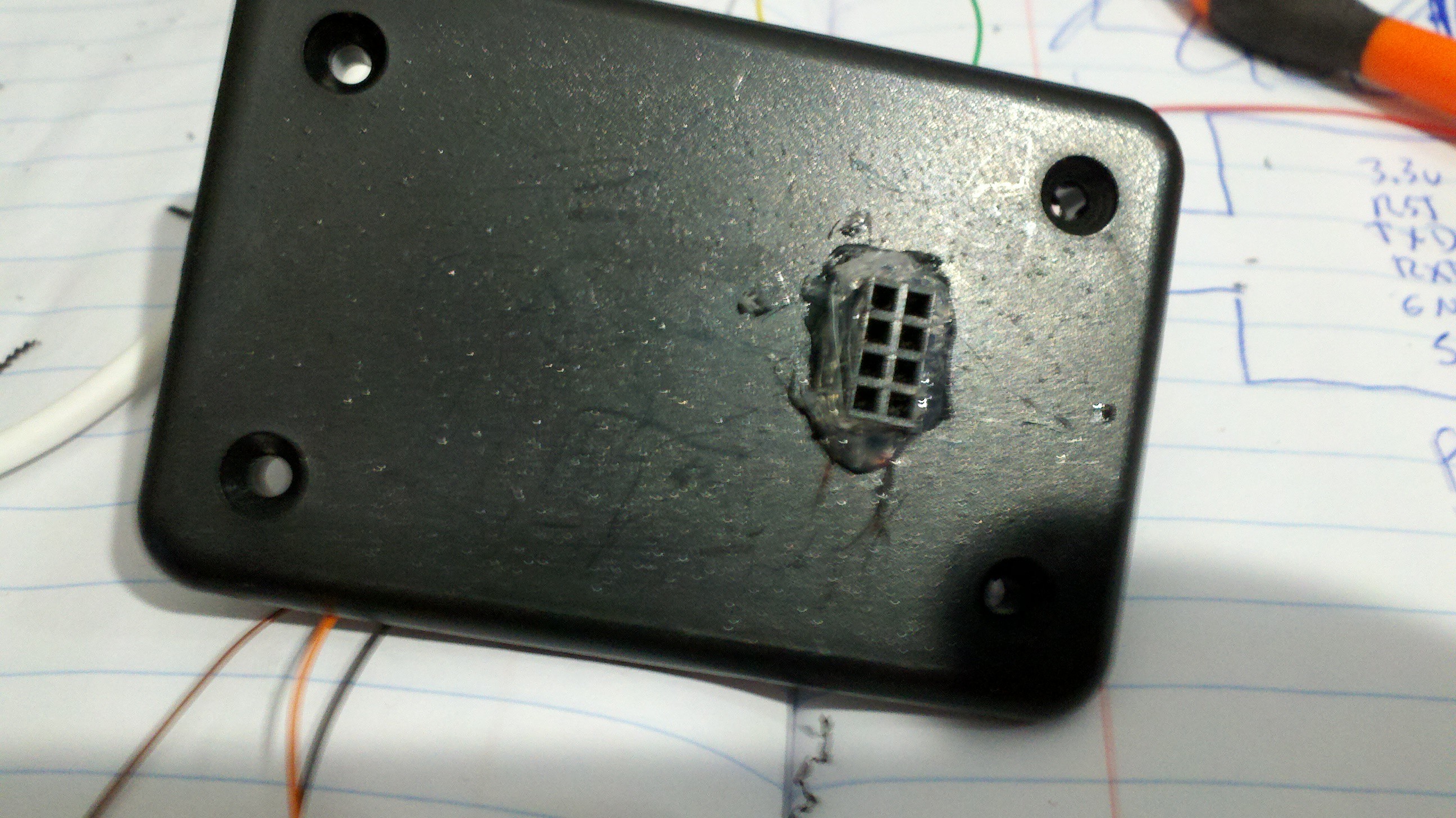
Since I wanted to change the esp8266 out I needed easy access to the socket. I cut a hole in the top of the plastic case just large enough for the 2x4 header the esp8266 uses. After final assembly I used hot melt glue to hold it in place but similar "super glues" would have also worked.
![]()
-
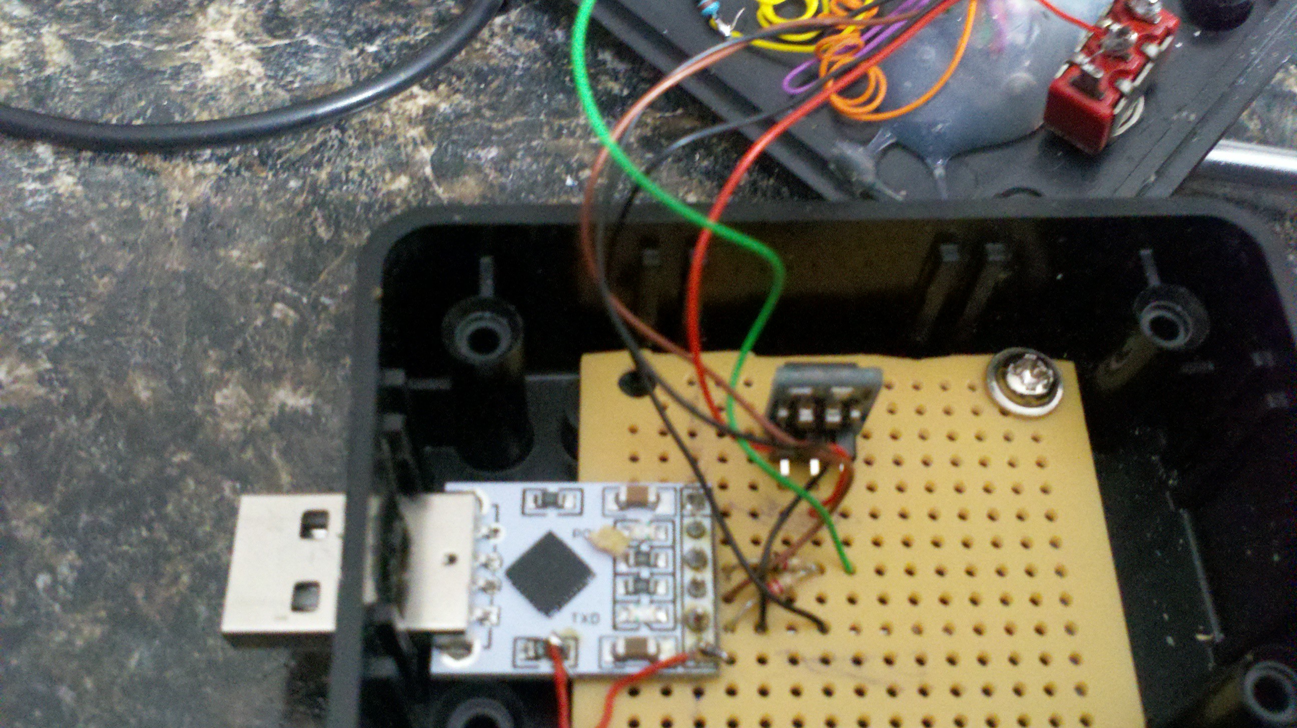
7Step 7
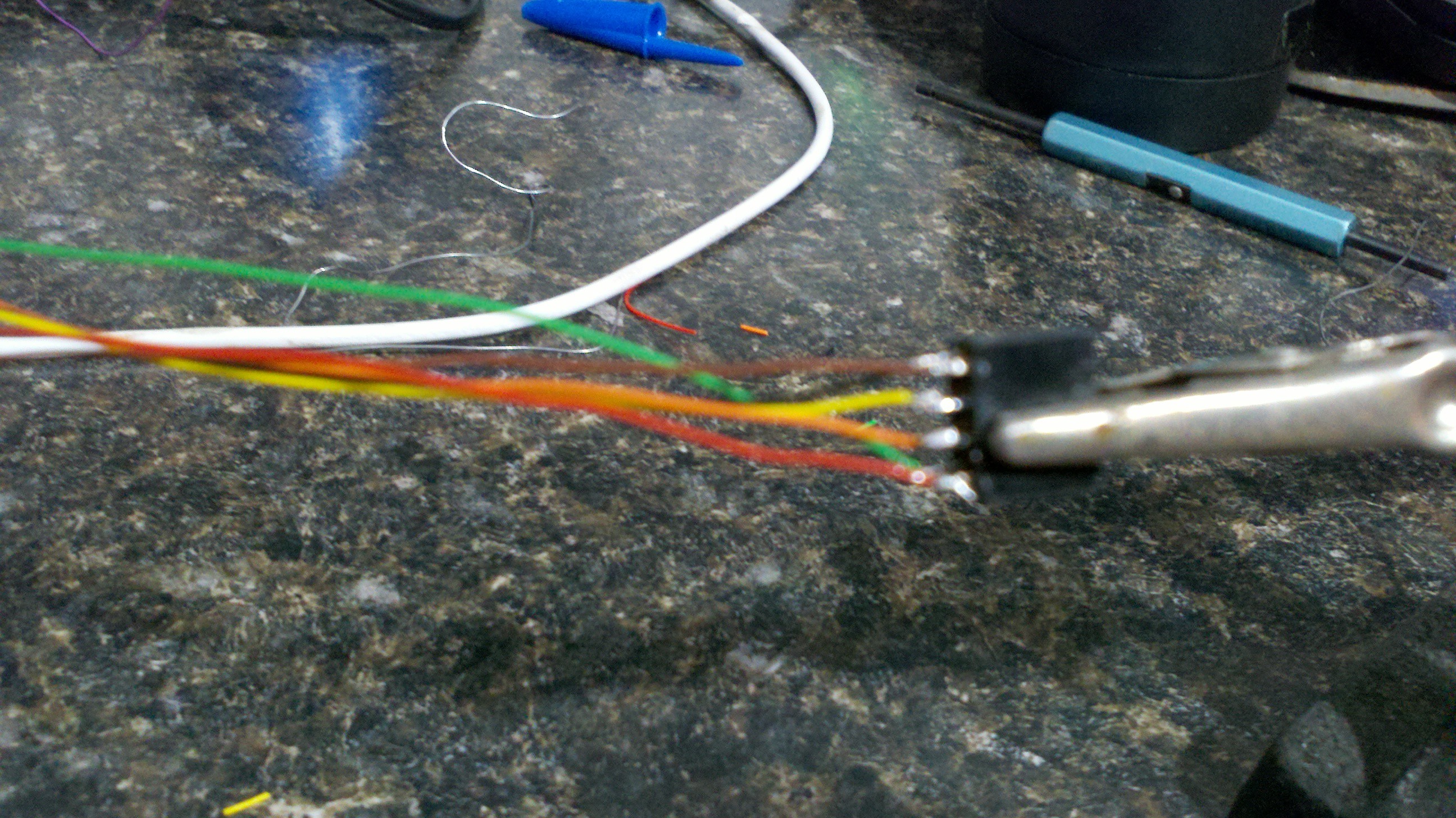
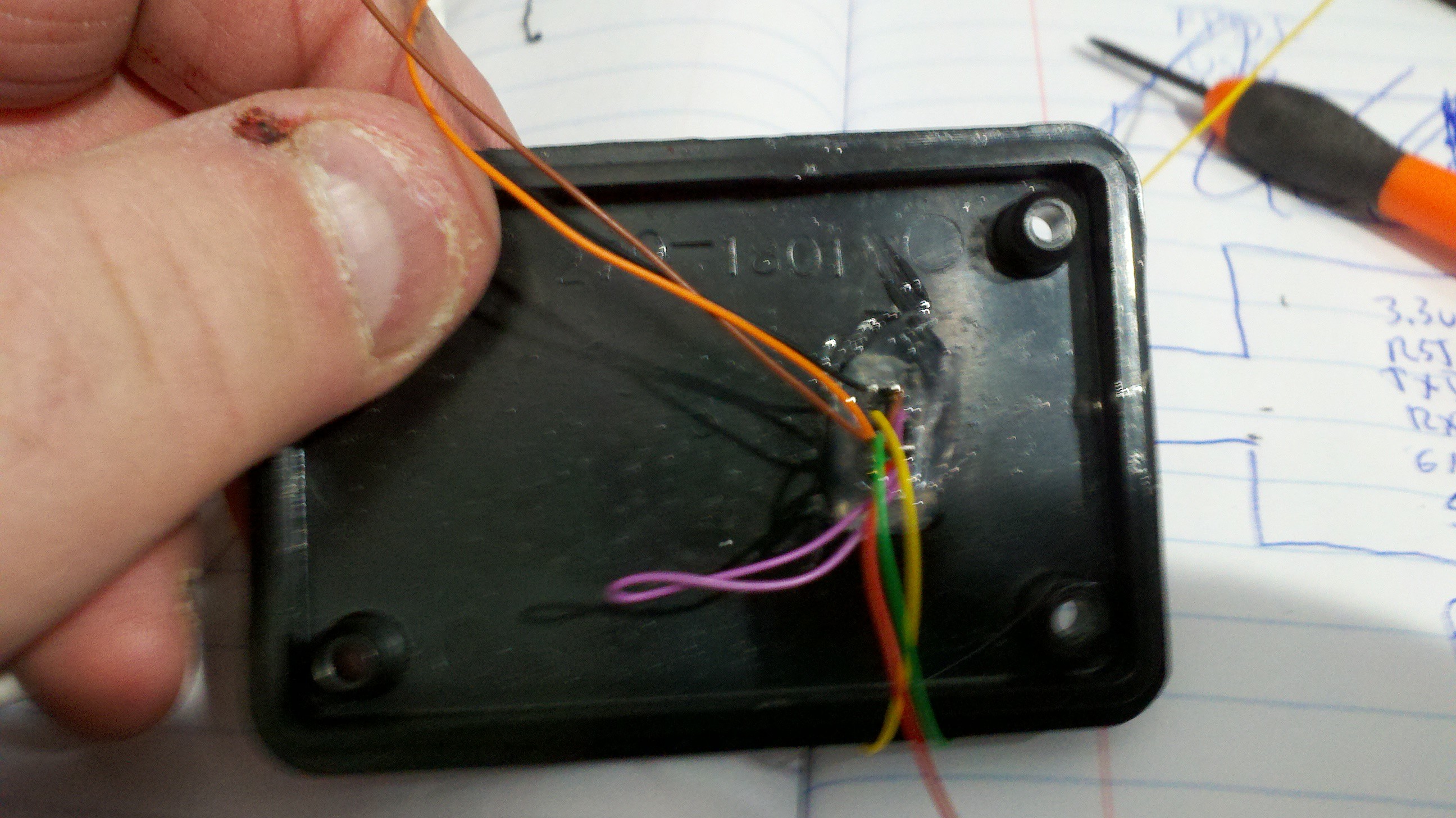
![]()
Wire the 2x4 connector. I used wirewrap wire and extended the socket with wires that were long enough for the case to be opened if needed.
Fit into the box top and glue as needed.
![]()
-
8Step 8
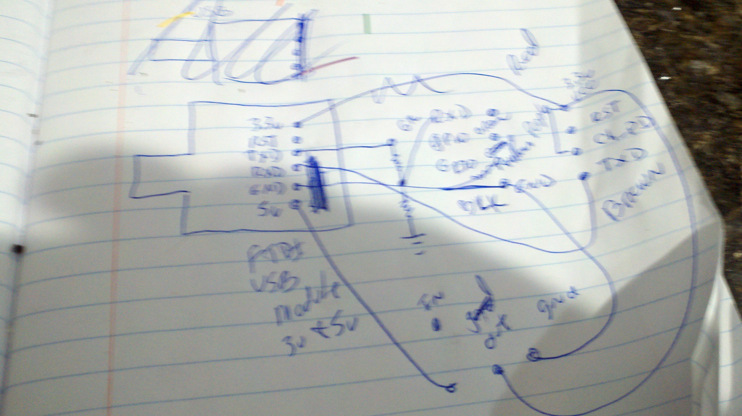
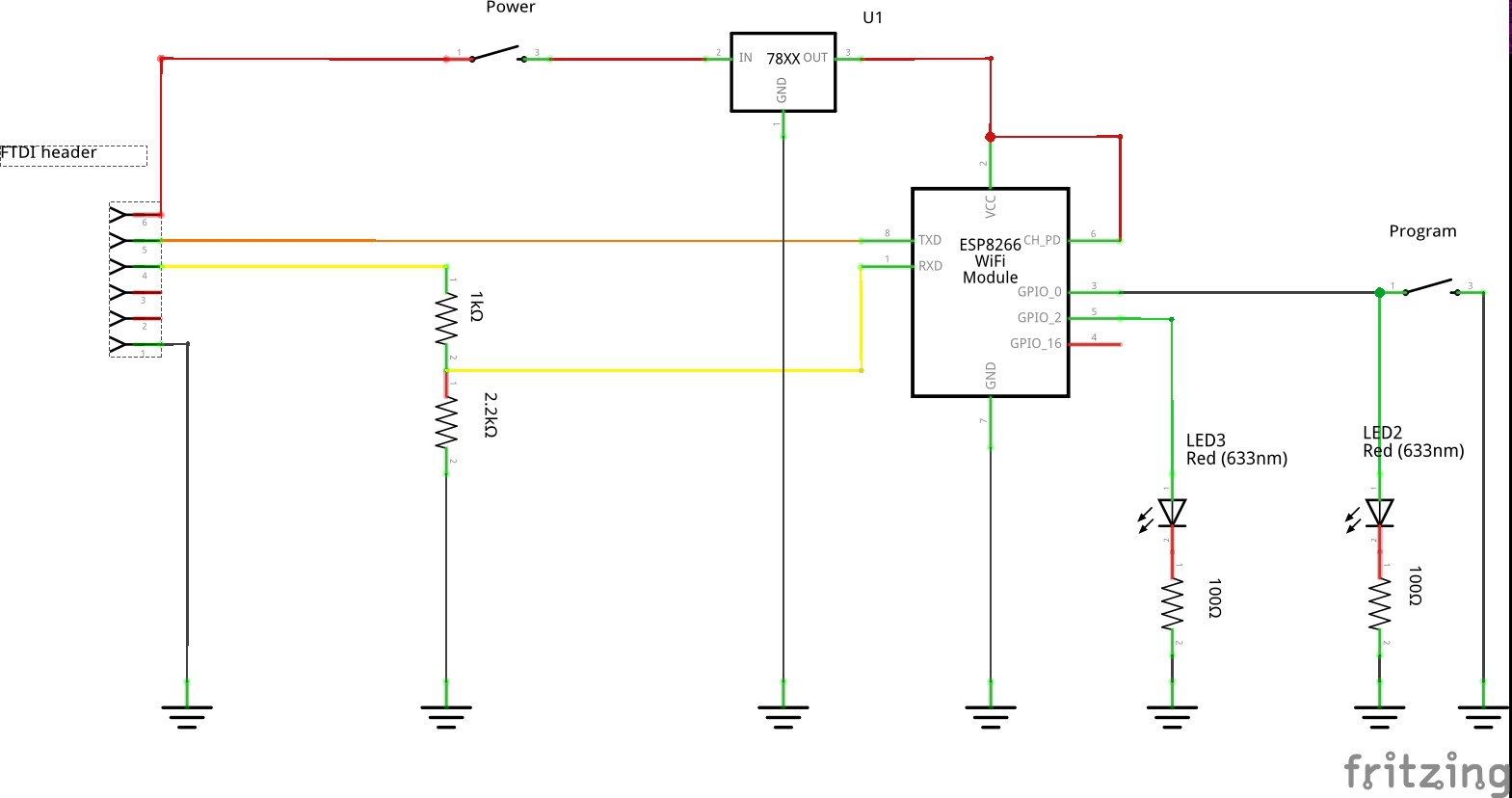
Here is my chicken scratch schematics I started my work from.
![]()
Here is a bit cleaner version of the schamatics. The ftdi headers users the 5v line (red), RXD line in orange, TXD line through the voltage diver in yellow, and Ground.
The two switches are used for power and setup program mode with the LED connected to the GPIO pins.
![]()
-
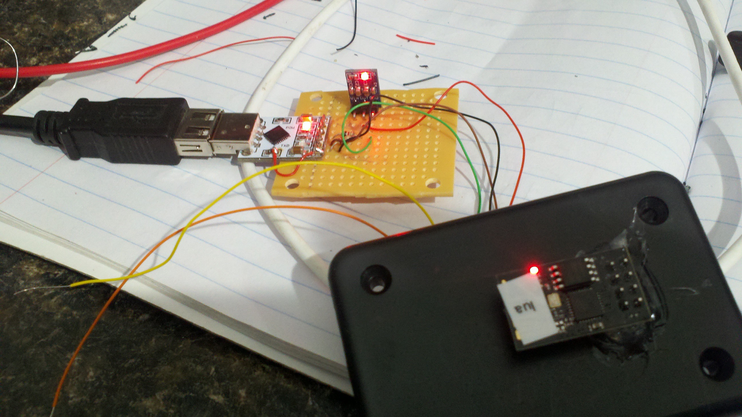
9Step 9
Here are some of the wires complete and basic power test being performed.
![]()
-
10Step 10
Wiring up the header and the voltage regulator.
![]()
![]()
ESP8266-01 Development board
A quick and easy dev board for the esp8266-01 board
Discussions
Become a Hackaday.io Member
Create an account to leave a comment. Already have an account? Log In.